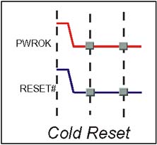
Cold Reset
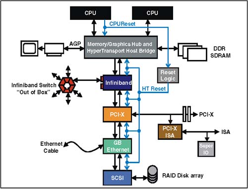
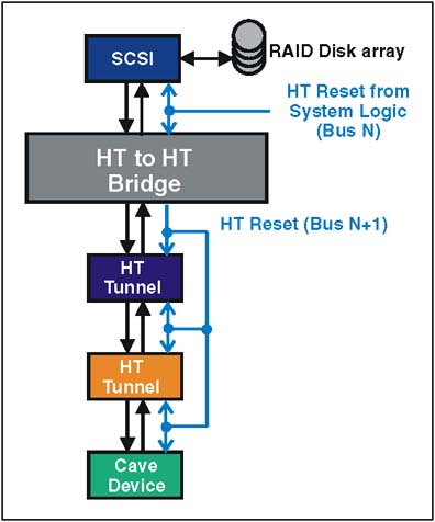
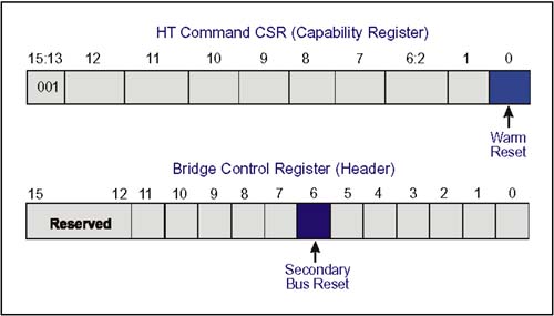
| Cold Reset is signaled during the power-up sequence under hardware control. This section details the sources, effects, and characteristics of a HyperTransport cold reset. Sources of Cold ResetIn addition to the hardware generation of cold reset during the powerup sequence, platform developers may also provide hooks for generating cold reset under software control. An optional method of generating a HyperTransport cold reset is defined by the specification for the secondary bus of a HT-to-HT bridge (discussed on page 278). However, software generation of cold reset for the secondary side of the Host-to-HT bridge can be implementation specific. Resetting the Primary HT BusSome implementation-specific mechanism must be defined to initiate a cold reset at powerup. The HT specification does not precisely define the source of HT cold reset for the system. It may be generated by system board logic or could be incorporated into the Host to HT bridge or other HT device residing on the system board. Figure 12-1 illustrates an example of HT RESET# generation and distribution. Figure 12-1. Example of Reset Distribution in an HT System Further, the specification does not require a software controlled method of cold reset generation. However, a host bridge could optionally implement a mechanism similar to that provided by the bridge control register of an HT-to-HT bridge. (See next section.) Once reset is signalled, any HT device has the option of extending it (via open drain signaling) to ensure the amount of time it needs to complete its internal initialization. In this way, reset remains asserted until the last HT device in the chain completes its initialization. All HT devices that signal cold reset must correctly sequence RESET# and PWROK as discussed in "Signalling and Detecting Cold Reset" on page 280. Resetting Secondary Side of HT-to-HT BridgeAn HT Bridge is required to propagate cold reset from its primary to its secondary side, but is not allowed to propagate any form of reset from its secondary to primary side. Thus, when the HT-to-HT Bridge initiates an HT cold reset to its secondary side, it will be distributed to all devices in the downstream chain as depicted in Figure 12-2. Figure 12-2. Example HT-to-HT Bridge Forwarding Cold Reset HT defines a optional method for HT-to-HT Bridges to generate a cold reset on the secondary bus under software control. This is done via two HT-to-HT Bridge configuration registers, the bridge control register in the configuration header and the command register located in the HT capability registers. These registers are depicted in Figure 12-3 on page 280. Each of these registers has a bit that in combination permits the generation of cold reset as follows :
Figure 12-3. Bridge Control Register Can Force Cold Reset When a cold reset is selected, the bridge will deassert PWROK as part of the reset sequence, thereby causing a cold reset. It is the responsibility of hardware to sequence PWROK and RESET# correctly, as described in "Signalling and Detecting Cold Reset" on page 280. Signalling and Detecting Cold ResetCold reset is detected when RESET is asserted and PWROK is deasserted (i.e., power is ramping up but not yet stable) on the same clock edge as illustrated in Figure 12-4 on page 280. Figure 12-4. Cold Reset Signalling The required sequencing of PWROK and RESET# is described below and illustrated in Figure 12-5 on page 281. Valid cold reset requires that PWROK be asserted for at least 1 ms after the HT power and clocks have stabilized. Also RESET# must be asserted at least 1 ms before PWROK is valid, and remain asserted for at least 1 ms after a valid PWROK. Note that the state of RESET# is undefined during some time before PWROK is asserted. A device may require RESET# to remain low for longer than 1 ms after PWROK is asserted to stabilize its transmit clocks. This ensures that all devices are ready to transfer information prior to the deassertion of reset. Figure 12-5. RESET# and PWROK Sequence and Timing Requirements Effects of Cold ResetCold reset initiates the link initialization process and forces all HT devices and HT links in the fabric to their default state. The default condition includes:
Chapter 12, entitled "Reset & Initialization," on page 275 details the required configuration registers and their default states. |
EAN: 2147483647
Pages: 182