Configuring an IKE VPN in Simplified Mode
Here we will create a VPN from ExternalFW to our branch office firewall, BranchFW, using Simplified mode. The two firewalls are managed by the same management station. Be sure to define network objects for the networks that will be participating in your VPN domain. We will use LAN and BranchNet (10.0.0.0/24) for these networks. In this example, we use Simplified mode to configure the VPNs. Remove the Traditional mode configurations, if any, that you defined previously.
Defining Objects
For any site-to-site VPN, you need to create and properly configure certain network objects, including both gateways and the networks or group objects representing your VPN domains.
Local Gateway
In ExternalFW s Properties window, select the Topology tab, as shown in Figure 10.3. This is where you will define the VPN domain for your local gateway. Under VPN Domain , select Manually Defined , and choose your local network (LAN) from the drop-down list. Selecting Manually Defined also allows you to restrict the networks that are accessible via a VPN in the event that you do not want your entire network to be available through the VPN. If you have your topology configured correctly, you can instead choose All IP Addresses behind Gateway based on Topology information . This option summarizes all the networks behind interfaces defined as internal and dynamically creates the VPN domain for you.
Remote Gateway
Configuration of the remote gateway is an identical process. Don t forget to define your VPN domain under the Topology tab, by opening the Topology tab of the Check Point Gateway Properties window (refer back to Figure 10.3). Under VPN Domain , select Manually Defined , and choose your remote network (BranchNet) from the drop-down list.
Creating the VPN Community
A VPN community is the way multiple VPN gateways communicate with, and encrypt between, each other. Three types of VPN communities are available in Check Point NG AI:
-
Remote access Used for easily defining client-to-site VPN connections. Only one is allowed throughout the entire management infrastructure.
-
Meshed This type of site-to-site VPN topology allows all participating gateways to communicate directly with any other gateway in the community. This is the simplest way of configuring site-to-site VPNs because it allows everything to VPN to everything else. A meshed VPN is used most often when multiple corporate offices all need to VPN with each other directly.
-
Star A star configuration, also known as a hub-and-spoke configuration, is a site-to-site VPN topology consisting of central gateways and satellite gateways. The satellite gateways, or spokes , communicate with only one or a few gateways, which are defined as central gateways. Satellites are typically remote or branch offices. The central gateways are typically headquarters, regional offices, or data center sites that communicate with all the satellite sites. Satellite gateways that need to encrypt data to other satellite gateways can do so through the central gateway(s) using VPN Routing. Satellites can also route all outbound traffic (including traffic destined for the Internet) through the hub gateway if necessary.
Select the VPN Manager tab in SmartDashboard to see the VPN communities. Predefined is the MyIntranet VPN Community. This is a meshed community. In Figure 10.7, a star community is used to explain the additional configuration options. You can select Manage VPN Communities or simply right-click in the top pane of the VPN Manager and select New Community to create a new community. After creating a star community, you will be presented the pane shown in Figure 10.7.
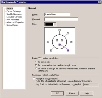
Figure 10.7: Star VPN Community Properties
Here you can define the traffic that will be sent from the satellites to the central gateways. Your options for enabling routing for satellites are as follows :
-
To center only Allows connectivity from the Branch to the Corporate Office and back.
-
To Center and to other satellites through center Allows one branch to communicate with another via each satellite s individual VPN to a central gateway.
-
To center, or through center to other satellites, to Internet and other VPN targets Allows all access, including access to the Internet, to occur through the central gateway. This final option is not often used, but it can be very handy, depending on your needs.
The other configurable element on this page is the Community Traffic Security Policy. By checking the Accept all encrypted traffic check box, you do not have to create any rules in the Rule Base. It will emulate a Frame Relay network in that no access controls will need to be defined in the security policy Rule Base. An implied rule will be added to the top of the Rule Base. All traffic will be accepted on Rule 0 in SmartView Tracker, though only if you define it to be logged in the Global Properties Logging tab. You can see these rules by selecting View VPN Rules . Keep in mind, however, that even though the all traffic will be accepted, it will still be subject to the enforcements of the firewalls, including three-way TCP handshake, SmartDefense, and more.
Next , select Central Gateways from the tree on the left and add ExternalFW. If we had multiple firewalls acting as central gateways, we could also select to mesh all the central gateways together, removing the need for another meshed VPN community. Now select the Satellite Gateways option on the left and add the BranchFW. You can also exclude certain services from being encrypted as part of the VPN community using the Excluded Services option from the left. When VPN Properties is highlighted, as shown in Figure 10.8, define the IKE (key exchange) and IPSec (encrypted network traffic) encryption algorithms and data integrity algorithms to be used for all VPN communications for this community.
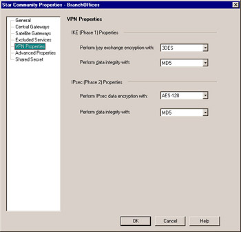
Figure 10.8: VPN Properties
VPN Properties includes the configuration settings most administrators are concerned with. However, more goes on behind the scenes. Check Point s open and configurable nature shows the administrator the default settings and allows them to be changed easily and quickly for all VPNs between gateways participating in the community. This process is shown in Figure 10.9.
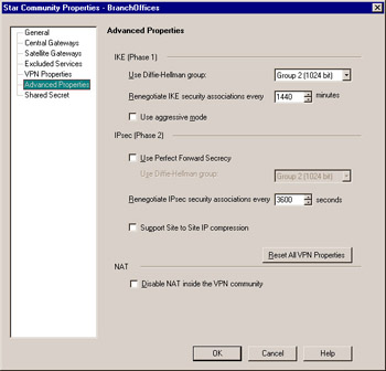
Figure 10.9: Advanced VPN Properties
Phase 1 always uses Diffie-Hellman to generate the keys. Selecting which Diffie-Hellman group is used can allow connectivity to other devices that use different levels of security. You can also use Diffie-Hellman to provide added security by selecting the Use Perfect Forward Secrecy check box. Here you can also define the length of time between key renegotiations, whether to use IP compression before encrypting the traffic, and whether to use aggressive mode to complete the key exchange in six packets rather than three packets.
The final option in this page is Disable NAT inside the VPN community . Because most of the networks behind the VPN gateways will be private (invalid) IP addresses, NAT will likely be applied to allow systems to communicate out to the Internet. By checking this box, any traffic through the VPN will not be subject to NAT rules applied by objects and the NAT Rule Base. It will, however, be subject to IP Pool NAT after the destination gateway has decrypted it, if applicable .
Adding VPN Rules
If you did not check the Accept all encrypted traffic check box for the VPN community (refer back to Figure 10.7), you will want to modify your Rule Base so that traffic between LAN and BranchNet is encrypted. Similar to, but not the same as, Traditional mode, this is done by adding two rules to your Rule Base.
You will notice that there is a new column in a Simplified mode policy: the VPN column. You will also notice that the Action column does not have Encrypt or Client Encrypt options. The VPN column defines how rules will be applied to all traffic (encrypted and cleartext), only site-to-site VPN connections, or only traffic encrypted through certain VPN communities. Figure 10.10 shows selection of only the BranchOffices VPN community.
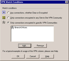
Figure 10.10: VPN Match Conditions
Next you need to define the following rules to allow traffic through the VPN. You could easily create a single rule allowing all traffic through any site-to-site VPN community, but the most advisable technique is to only allow the necessary traffic. To emulate the rules previously shown in the Traditional mode configuration, create the rules as defined next.
One rule specifies the following:
-
Source LAN
-
Destination BranchNet
-
Service Any
-
VPN BranchOffices
-
Action Accept
-
Track Log
The other specifies the following:
-
Source BranchNet
-
Destination LAN
-
VPN Branch Offices
-
Service Any
-
Action Accept
-
Track Log
When the rules have been created, they should resemble Figure 10.11.
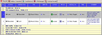
Figure 10.11: VPN Community Encryption Rules
Note that we do not have a rule to allow the IKE traffic to talk from one firewall to the other. As in Traditional mode, this is because it is part of the Global Properties. A rule to allow IKE between the two gateways is only necessary if you have Accept VPN-1 & FireWall-1 control connections unchecked in your security policy s Global Properties window. This option is checked by default, so in most cases you won t need a rule to be manually defined.
Now that the rules have been created, let s push the policy and test the VPN.
Testing the VPN
Once the configuration is complete, install the security policy on both gateways. Try to establish a connection from a host in your local VPN domain to a host in the remote gateway s VPN domain. You should see packets with a local source address and a remote destination address being encrypted on the way out the local gateway and corresponding packet decryptions on the remote gateway (see Figure 10.12). If this is not immediately apparent, or if you see errors in the log, refer to the following section for some troubleshooting tips. You should see key install entries in the log, then decrypt and encrypt logs.

Figure 10.12: SmartView Tracker Entries Showing Encrypts, Decrypts, and Key Exchanges
Debugging VPNs
Troubleshooting VPNs has traditionally been rather difficult. There are certain steps you can take to make troubleshooting and testing of VPN deployments easier:
-
Enable implied rule logging in the security policy Global Properties window. If you choose to accept all traffic when using VPN communities, make sure you are logging that traffic as well.
-
On the security policy Log and Alert tab in the Global Properties window, enable all three encryption-specific log events:
-
VPN successful key exchange
-
VPN packet handling errors
-
VPN configuration and key exchange errors
-
-
Disable NAT by adding one or more manual rules to the NAT Rule Base that force traffic between opposing VPN domains to be Original, as in Figure 10.13, or un-NATed. NAT can be used with VPNs; however, disabling it when possible allows for cleaner testing and simpler debugging.
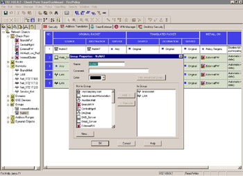
Figure 10.13: Address Translation Disabled Between VPN Domains with Manual Rules -
Be aware that the gateways participating in the VPN and perhaps the management stations need to communicate prior to the VPN tunnel being established (key exchange, protocol negotiation, and so forth). You may need a rule in your Rule Base explicitly allowing this communication (refer back to the preceding IKE encryption Rule Base examples).
Be aware of where in your Rule Base your stealth rule is and how this might impact such communication. Implied rule and VPN logging, again discussed previously, will show you such communication in a default installation.
-
Remember to test traffic from VPN domain to VPN domain, not from gateway to gateway. Normally, gateways are not included in VPN domains, so they cannot provide a platform for reliable tests.
-
Be aware that using just ICMP (Ping) tests may not tell whether or not a VPN is working correctly. This especially applies if you don t have control over the other VPN endpoint. Administrators are often leery of allowing ICMP through their firewall and/or border routers and may be dropping it with implicit or explicit rules before any encryption can take place. A better test, and one that works on any platform with a Telnet binary, is to Telnet to a port other than the traditional port 23, using one that you know is open. So, for example, if your VPN peer has a DNS server in its VPN domain, telnet < IP of DNS server > 53 would show you that you could establish a TCP connection through your VPN tunnel.
-
Your gateway may attempt to encrypt packets, even if key exchange is not complete, causing you to wonder why a VPN is failing to work if encryption is taking place. If you filter your Log Viewer for Key Install under the Action column, you will see key exchange as it occurs. The Info field of each log entry in this case may contain useful error messages relevant to key exchange errors.
-
For every encrypt action on your gateway, your partner s firewall should show a corresponding decrypt action. You may or may not have access to those logs, so the preceding tips can help you test in that case.
-
Look for configuration examples when choosing to interoperate with other non-Check Point devices. Many IKE devices, though certified in many ways to be interoperable, do not choose configurations or negotiate when presented with options during the key exchange. Notorious for this are Cisco devices. In addition, look for the exact device, model, and version in use on the other end. The built-in options and settings will vary between different VPN products from the same manufacturer (for example, Cisco PIX, Cisco VPN Concentrator, Cisco VPN-enabled router) and between versions.
-
Check to see how the other end is expecting your gateway to present its networks (network address and subnet mask). It may be necessary to change the ike_use_largest_possible_subnets option in object_5_0.C to False (True is the default).
Considerations for External Networks
It is important that all encryption rules have the same exact parameters defined in their respective encryption properties dialog box. Your VPN will likely fail if they do not. This is easy to check when you manage both the local and remote gateways, but it can be harder to verify when the remote gateway is managed by another management station or even another company. Typically this coordination is done via telephone, agreed on ahead of time, as in We will use IKE with 3DES encryption, SHA-1 data integrity, key exchange for subnets, and no perfect forward secrecy. Most VPN failures are a result of someone changing his or her respective VPN parameters, causing key exchange, key renegotiations, encryption, or decryption to fail.