Section 4.2. A Motherboard Tour
4.2. A Motherboard TourA motherboard is so complex and has so many components and connections that it can be overwhelming to someone who is not used to working inside PCs. As is true of many things, though, the easiest way to understand the working of the whole is to understand the working of the individual parts. So let's take the $2 tour of a modern motherboard, where you'll learn the functions of each important component and how to identify those components visually. To begin, let's examine a block diagram of a chipset. Figure 4-4 shows the major components and functions of the Intel 925XE chipset. (Other modern chipsets are similar.) The 925XE chipset uses two physical chips. The north bridge chip, which Intel calls the MCH (Memory Controller Hub), is the blue box labeled 82925X MCH. The MCH arbitrates and coordinates communications between the processor, memory, and the PCI Express video adapter. The MCH provides very high bandwidth channels: 6.4 GB/s between the MCH and processor; 8.0 GB/s between the MCH and the video adapter; and 8.5 GB/s between the MCH and memory. Figure 4-4. Block diagram of the Intel 925X chipset (image courtesy of Intel Corporation)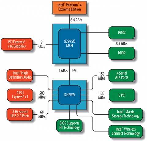 The south bridge chip, which Intel calls the ICH (I/O Controller Hub), is the blue box labeled ICH6RW. The ICH handles input/output functions, which work at much lower data rates than the processor, memory, and video channels. These channels include four 150 MB/s Serial ATA ports, six PCI slots with a cumulative 133 MB/s bandwidth, eight USB 2.0 ports with 60 MB/s bandwidth each, and four 500 MB/s PCI Express x1 slots. The ICH also handles such functions as embedded audio, the interface with the system BIOS, and wireless networking. Figure 4-5 maps these chipset features to the component layout on a real-world motherboard. For illustrative purposes, we've used an Intel D925XECV2 motherboard, but any recent motherboard has similar features and layout. Not all of the components shown are present on all motherboards, and the exact positioning of some components may differ, but the essentials remain the same. Figure 4-5. Component layout on a typical motherboard (image courtesy of Intel Corporation)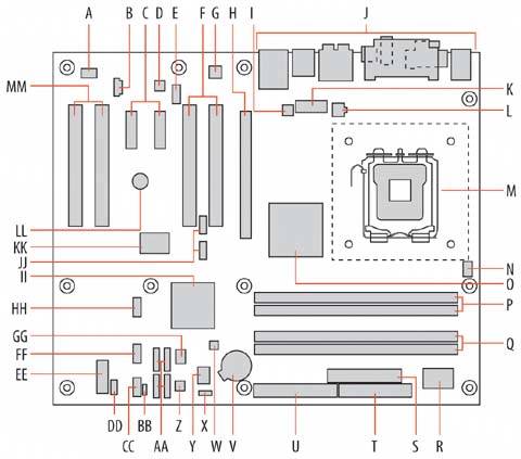
The left rear quadrant of the motherboard, shown in Figure 4-6, is dominated by expansion slotstwo pairs of white PCI slots bracketing a pair of PCI Express x1 slots, with a black PCI Express x16 video adapter slot at the far right. The white auxiliary rear fan connector is visible centered above the left pair of PCI slots. The yellow connector at top center is the front-panel audio connector, with the audio codec chip to its upper left. The Gigabit Ethernet controller chip is visible centered between the two mounting holes on the upper right. The round object below the PCI Express x1 slots is the system speaker. The large chip at bottom center is the FireWire controller, and the two blue header-pin connectors to its right are the front-panel FireWire interface connectors. Figure 4-6. Left rear quadrant of the D925XECV2 motherboard (image courtesy of Intel Corporation)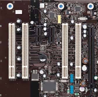 The right rear quadrant of the motherboard, shown in Figure 4-7, is dominated by the processor socket (lower right), the heatsink for the north bridge chip (bottom left), and a top view of the rear I/O panel (top). The group of three white connectors at the upper left are, from left to right, the rear case fan connector, the alternate power connectorused to provide additional current to the motherboard if the power supply has a 20-pin main power connector rather than a 24-pin connectorand the ATX12V power connector. The CPU fan connector is visible at the lower-right corner of the image. Figure 4-7. Right rear quadrant of the D925XECV2 motherboard (image courtesy of Intel Corporation)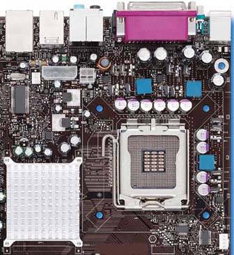 Figure 4-8 shows the rear I/O panel connectors. Legacy PS/2 mouse (top) and keyboard connectors are visible at the far left. The second group of connectors includes a parallel (LPT) port at the top and a 9-pin serial port at the lower left. At the bottom left of this group are coax (round) and optical (square) digital audio-out ports. The third group of connectors are all audio connectors, which can be configured for various functions. The fourth group of connectors has a FireWire connector at the top, with two USB 2.0 connectors beneath it. The fifth group of connectors has a Gigabit Ethernet connector at the top, with two more USB 2.0 connectors beneath it. Figure 4-8. Rear I/O panel connectors (image courtesy of Intel Corporation)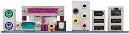
The left front quadrant of the motherboard is shown in Figure 4-9. The round object at the lower right is the battery. The large chip immediately to its left is the Firmware Hub (FWH), with the orange BIOS Setup Configuration jumper block below it. The white object to the left of the jumper block is the front case fan power connector. Above that power connector is the Trusted Platform Module (TPM) chip, and a group of four Serial ATA interface connectors appears to the left of the TPM chip and power connector. The large silver object at right center is the heatsink for the ICH6 south bridge chip. The black header pin connector to the left of the south bridge heatsink is one front-panel USB connector, with a second identical connector below it. The multicolored jumper block at the center bottom edge of the motherboard is the front-panel connector. Figure 4-9. Left front quadrant of the D925XECV2 motherboard (image courtesy of Intel Corporation)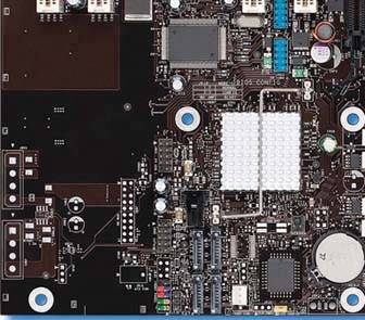 Figure 4-10 shows the right front quadrant of the motherboard, with the two Channel A memory slots at the top and two Channel B memory slots beneath them. The large chip at the lower right is the supplemental I/O controller chip, with the white ATX main power connector to its left. The black ATA interface connector is at the bottom left edge of this image, with the floppy drive interface connector immediately to its right. Figure 4-10. Right front quadrant of the D925XECV2 motherboard (image courtesy of Intel Corporation)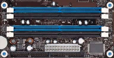 |
EAN: 2147483647
Pages: 126