Securing Your OSPF Network
When you create dynamic access lists, remember the following:
User authentication is successful when the following router events occur:
You can verify that this operation is successful on the router either by asking the user to test the connection or by using the show-access-lists command to view dynamic access lists. The following sample display illustrates what the end-user might see after successfully completing the authentication process. Notice that the connection was closed immediately after the password was entered and authenticated. The temporary access list entry has already been created, and the host that initiated the Telnet session has access inside the firewall: OSPF_Router# telnet corporate Trying 172.21.52.1 ... Connected to corporate.abc.com. Escape character is '^]'. User Access Verification Password: Connection closed by foreign host. Additional Resources on Lock-and-Key Security This section introduced several new commands. If you need further information regarding their configuration and operation, see the following Cisco IOS publications:
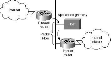
Deleting a Dynamic Access List If it becomes necessary to delete a dynamic access list, enter the following command (in privileged EXEC mode) for the process: clear access-template [access-list-number | name] [dynamic-name] [source] [destination] You can display temporary access list entries when they are in use. After a temporary access list entry is cleared by you or by the absolute or idle timeout parameter, it can no longer be displayed. The number of matches displayed indicates the number of times the access list entry was hit. Display Dynamic & Temporary Access List Entries It is always a good rule of thumb to check and verify the entries you have created before committing them to the router’s memory. To view dynamic access lists and any temporary access list entries that are currently established, perform the following task in privileged EXEC mode: show access-lists [access-list-number] Lock-and-Key Access Example The following example shows how to configure lock-and-key access. In this example, login is on the TACACS+ server, so no autocommand command appears in this configuration. Lock-and-key access is configured on the BRI0 interface. Four VTY ports are defined with the password “cisco.” aaa authentication login default tacacs+ enable aaa accounting exec stop-only tacacs+ aaa accounting network stop-only tacacs+ enable password ciscotac ! isdn switch-type basic-dms100 ! interface ethernet0 ip address 172.18.23.9 255.255.255.0 !! interface BRI0 ip address 172.18.21.1 255.255.255.0 encapsulation ppp dialer idle-timeout 3600 dialer wait-for-carrier-time 100 dialer map ip 172.18.21.2 name diana dialer-group 1 isdn spid1 2036333715291 isdn spid2 2036339371566 ppp authentication chap ip access-group 102 in ! access-list 102 dynamic testlist timeout 5 permit ip any any access-list 102 permit tcp any host 172.18.21.2 eq 23 ! ip route 172.18.250.0 255.255.255.0 172.18.21.2 priority-list 1 interface BRI0 high tacacs-server host 172.18.23.21 tacacs-server host 172.18.23.14 tacacs-server key test1 tftp-server rom alias all ! dialer-list 1 protocol ip permit ! line con 0 password cisco line aux 0 line VTY 0 4 password cisco ! Chapter SummaryThis chapter began with discussion of the various threats against your network in the network security section. Fortunately, you learned several defenses that were already available for your network. The section, “Golden Rules of Designing a Secure Network,” covered a variety of questions that you should answer when considering how to design a comprehensive security policy for Enterprise networks. This section also discussed the many reasons that network security should be part of your network design from the beginning as opposed to an afterthought. The section, “Securing Your OSPF Network,” covered many different techniques that can be used to increase the overall security of your network. That section also covered the neighbor authentication features that are found in OSPF and how to configure and deploy your routers to make use of this desirable OSPF feature. In the final section, “Configuring Traffic Filters,” the various types of access lists were covered, along with a sample network that illustrated their deployment within a network router firewall design. The case study for this chapter will include the process of designing and setting up a router-based firewall structure for your network. Case Study: Designing Your Router Firewall ArchitectureThis case study discusses the deployment of Cisco PIX Firewall within a network. A router firewall architecture is a network structure that exists between you and the outside world, the Internet for example, that is designed to protect your network from intruders (that is, cyber thieves). In most circumstances, intruders are represented by the global Internet and the thousands of remote networks it interconnects. Typically, a network firewall consists of several different machines, as shown in Figure 10-2.
|
EAN: 2147483647
Pages: 200