Virtual LANs
| As noted earlier, a broadcast domain includes all devices that receive each other's broadcasts (and multicasts). All the devices connected to one router port are in the same broadcast domain. Routers block broadcasts (destined for all networks) and multicasts by default; routers only forward unicast packets (destined for a specific device) and packets of a special type called directed broadcasts. Typically, you think of a broadcast domain as being a physical wire, a LAN. But a broadcast domain can also be a VLAN, a logical construct that can include multiple physical LAN segments. Note IP multicast technology, which enables multicast packets to be sent throughout a network, is described in Chapter 10, "Other Enabling Technologies." Note An IP directed broadcast is a packet destined for all devices on an IP subnet, but which originates from a device on another subnet. A router that is not directly connected to the destination subnet forwards the IP directed broadcast in the same way it would forward unicast IP packets destined to a host on that subnet. On Cisco routers, the ip directed-broadcast interface command controls what the last router in the path, the one connected to the destination subnet, does with the packet. If ip directed-broadcast is enabled on the interface, the router changes the directed broadcast to a broadcast and sends the packet, encapsulated in a Layer 2 broadcast frame, onto the subnet. However, if the no ip directed-broadcast command is configured on the interface, directed broadcasts destined for the subnet to which that interface is attached are dropped. In Cisco Internet Operating System (IOS) version 12.0, the default for this command was changed to no ip directed-broadcast. Key Point We found the Cisco definition of VLANs to be very clear: "[A] group of devices on one or more LANs that are configured (using management software) so that they can communicate as if they were attached to the same wire, when in fact they are located on a number of different LAN segments. Because VLANs are based on logical instead of physical connections, they are extremely flexible."[2] Figure 2-6 illustrates the VLAN concept. On the left side of the figure, three individual physical LANs are shown, one each for Engineering, Accounting, and Marketing. (These LANs contain workstationsE1, E2, A1, A2, M1, and M2and serversES, AS, and MS.) Instead of physical LANs, an enterprise can use VLANs, as shown on the right side of the figure. With VLANs, members of each department can be physically located anywhere, yet still be logically connected with their own workgroup. Thus, in the VLAN configuration, all the devices attached to VLAN E (Engineering) share the same broadcast domain, the devices attached to VLAN A (Accounting) share a separate broadcast domain, and the devices attached to VLAN M (Marketing) share a third broadcast domain. Figure 2-6 also illustrates how VLANs can span across multiple switches; the link between the two switches in the figure carries traffic from all three of the VLANs and is called a trunk. Figure 2-6. A VLAN Is a Logical Implementation of a Physical LAN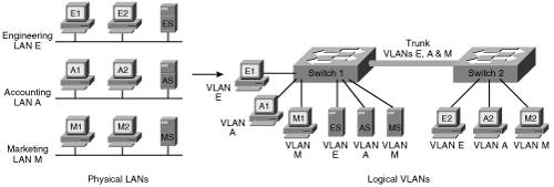 VLAN MembershipKey Point A switch port that is not a trunk can belong to only one VLAN at a time. You can configure which VLAN a port belongs to in two ways: statically and dynamically. Static port membership means that the network administrator configures which VLAN the port belongs to, regardless of the devices attached to it. This means that after you have configured the ports, you must ensure that the devices attaching to the switch are plugged into the correct port, and if they move, you must reconfigure the switch. Alternatively, you can configure dynamic VLAN membership. Some static configuration is still required, but this time, it is on a separate device called a VLAN Membership Policy Server (VMPS). The VMPS could be a separate server, or it could be a higher-end switch that contains the VMPS information. VMPS information consists of a MAC address-to-VLAN map. Thus, ports are assigned to VLANs based on the MAC address of the device connected to the port. When you move a device from one port to another port (either on the same switch or on another switch in the network), the switch dynamically assigns the new port to the proper VLAN for that device by consulting the VMPS. TrunksAs mentioned earlier, a port that carries data from multiple VLANs is called a trunk. A trunk port can be on a switch, a router, or a server. A trunk port can use one of two protocols: Inter-Switch Link (ISL) or IEEE 802.1q. ISL is a Cisco-proprietary trunking protocol that involves encapsulating the data frame between an ISL header and trailer. The header is 26 bytes long; the trailer is a 4-byte cyclic redundancy check (CRC) that is added after the data frame. A 15-bit VLAN ID field is included in the header to identify the VLAN that the traffic is for. (Only the lower 10 bits of this field are used, thus supporting 1024 VLANs.) The 802.1q protocol is an IEEE standard protocol in which the trunking information is encoded within a Tag field that is inserted inside the frame header itself. Trunks using the 802.1q protocol define a native VLAN. Traffic for the native VLAN is not tagged; it is carried across the trunk unchanged. Thus, end-user stations that don't understand trunking can communicate with other devices directly over an 802.1q trunk, as long as they are on the native VLAN. The native VLAN must be defined to be the same VLAN on both sides of the trunk. Within the Tag field, the 802.1q VLAN ID field is 12 bits long, allowing up to 4096 VLANs to be defined. The Tag field also includes a 3-bit 802.1p user priority field; these bits are used as class of service (CoS) bits for quality of service (QoS) marking. (Chapter 6, "Quality of Service Design," describes QoS marking.) The two types of trunks are not compatible with each other, so both ends of a trunk must be defined with the same trunk type. Note Multiple switch ports can be logically combined so that they appear as one higher-performance port. Cisco does this with its Etherchannel technology, combining multiple Fast Ethernet or Gigabit Ethernet links. Trunks can be implemented on both individual ports and on these Etherchannel ports. STP and VLANsCisco developed per-VLAN spanning tree (PVST) so that switches can have one instance of STP running per VLAN, allowing redundant physical links within the network to be used for different VLANs and thus reducing the load on individual links. PVST is illustrated in Figure 2-7. Figure 2-7. PVST Allows Redundant Physical Links to Be Used for Different VLANs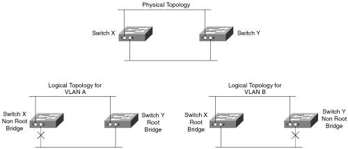 The top diagram in Figure 2-7 shows the physical topology of the network, with switches X and Y redundantly connected. In the lower-left diagram, switch Y has been selected as the root bridge for VLAN A, leaving port 2 on switch X in the blocking state. In contrast, the lower-right diagram shows that switch X has been selected as the root bridge for VLAN B, leaving port 2 on switch Y in the blocking state. With this configuration, traffic is shared across all links, with traffic for VLAN A traveling to the lower LAN on switch Y's port 2, while traffic for VLAN B traveling to the lower LAN goes out switch X's port 2. PVST only works over ISL trunks. However, Cisco extended this functionality for 802.1q trunks with the PVST+ protocol. Before this became available, 802.1q trunks only supported Common Spanning Tree (CST), with one instance of STP running for all VLANs. Multiple-Instance STP (MISTP) is an IEEE standard (802.1s) that uses RSTP and allows several VLANs to be grouped into a single spanning-tree instance. Each instance is independent of the other instances so that a link can be forwarding for one group of VLANs while blocking for other VLANs. MISTP therefore allows traffic to be shared across all the links in the network, but it reduces the number of STP instances that would be required if PVST/PVST+ were implemented. VLAN Trunking ProtocolKey Point The VLAN Trunking Protocol (VTP) is a Cisco-proprietary Layer 2 protocol that allows easier configuration of VLANs on multiple switches. When VTP is enabled in your network, you define all the VLANs on one switch, and that switch sends the VLAN definitions to all the other switches. On those other switches, you then have to only assign the ports to the VLANs; you do not have to configure the VLANs themselves. Not only is configuration easier, but it is also less prone to misconfiguration errors. A switch in a VTP domain (a group of switches communicating with VTP) can be in one of three modes: server (which is the default mode), client, or transparent mode. The VTP server is the one on which you configure the VLANs; it sends VTP advertisements, containing VLAN configuration information, to VTP clients in the same VTP domain, as illustrated in Figure 2-8. Note that VTP advertisements are only sent on trunks. Figure 2-8. VTP Eases VLAN Definition Configuration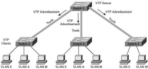 You cannot create, modify, or delete VLANs on a VTP client; rather, a VTP client only accepts VLAN configuration information from a VTP server. A VTP client also forwards the VTP advertisements to other switches. You can create, modify, or delete VLANs on a switch that is in VTP transparent mode; however, this information is not sent to other switches, and the transparent-mode switch ignores advertisements from VTP servers (but does pass them on to other switches). VTP pruning is a VTP feature that helps reduce the amount of flooded traffic (including broadcast, multicast, and unicast) that is sent on the network. With VTP pruning enabled, the switches communicate with each other to find out which switches have ports in which VLANs; switches that have no ports in a particular VLAN (and have no downstream switches with ports in that VLAN) do not receive that VLAN's traffic. For example, in Figure 2-8, switch 4 has no need for VLAN A traffic, so VTP pruning would prevent switch 1 from flooding VLAN A traffic to switch 4. VTP pruning is disabled by default. Inter-VLAN RoutingYou have learned how devices on one VLAN can communicate with each other using switches and trunks. But how do networked devices on different VLANs communicate with each other? Key Point Just like devices on different LANs, those on different VLANs require a Layer 3 mechanism (a router or a Layer 3 switch) to communicate with each other. A Layer 3 device can be connected to a switched network in two ways: by using multiple physical interfaces or through a single interface configured as a trunk. These two connection methods are shown in Figure 2-9. The diagram on the left in this figure illustrates a router with three physical connections to the switch; each physical connection carries traffic from only one VLAN. Figure 2-9. A Router, Using Either Multiple Physical Interfaces or a Trunk, Is Required for Communication Among VLANs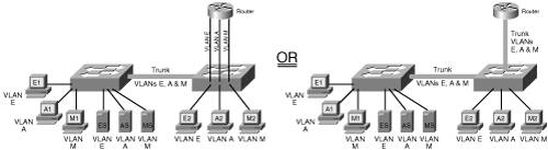 The diagram on the right in Figure 2-9 illustrates a router with one physical connection to the switch. The interfaces on the switch and the router have been configured as trunks; therefore, multiple logical connections exist between the two devices. When a router is connected to a switch through a trunk, it is sometimes called a "router on a stick," because it has only one physical interface (a stick) to the switch. Each interface between the switch and the Layer 3 device (whether physical interfaces or logical interfaces within a trunk) is in a separate VLAN (and therefore in a separate subnet for IP networks). |
EAN: 2147483647
Pages: 156