VPN and MAC Persistence
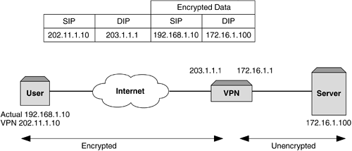
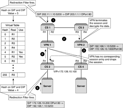
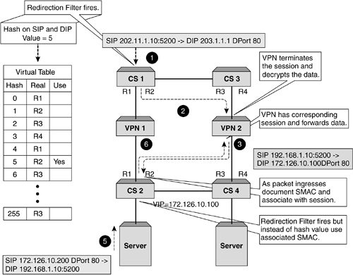
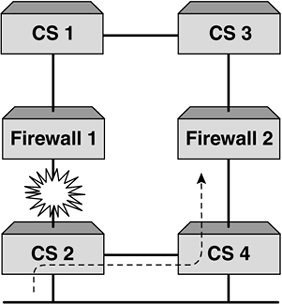
| VPNs are at the forefront of any security deployment these days, and most organizations realize the benefit this technology brings . Not only does it allow remote, secure access into your organization over a public network, but also it drastically reduces costs of having to support leased lines or dedicated dial-up links. When providing business-to-business type transactions, a VPN allows for rapid deployment and ease of management. As VPNs gain in popularity and importance, so to does the need to scale the solution as well as provide resilience. This is particularly important when performing transactions and business- related functions. Just like firewalls, load-balancing VPNs is a perfect solution that provides performance and resilience, but it too brings certain challenges. To understand these, it is important that we see how VPN data and addressing differs from that of traditional data. VPN in ActionA VPN is a connection between two devices that is often referred to as a tunnel . This tunnel allows encrypted data to be sent from any public network, and due to the encryption mechanisms used, ensures that the sensitive or important data is secure. There are proprietary methods as well as standards that dictate the method by which to encrypt and transmit data over a VPN. For the purpose of this section, we will assume that a VPN will encrypt your data and forward it to the correct destination. We will also assume that it will use a specific VPN address for the user and connect to the specified VPN termination point. Both the original SIP and DIP are encrypted within the VPN encapsulated packet. Typically, a VPN will consist of a central VPN or termination point, which is typically the head office, and then remote sites or tele-workers connect to the VPN from many different locations over a public network, which is usually the Internet. This connectivity and encryption is detailed in Figure 9-15. Figure 9-15. A typical VPN. What VPNs allow us to do is set up a link that to the outside world looks like it is from a user to the VPN termination point. While this is exactly what the encapsulated packet looks like, the real destination address is encrypted within the data portion of the packet. It is the VPN termination point that first allows the session to be set up and then decrypts the data portion, strips off the encapsulation, and forwards the packet to the correct destination. Obviously, a VPN is a stateful device, as it will need to see the return packet, tie it to the incoming session, and perform encryption and encapsulation before routing the packet back to the source. Load Balancing VPNsSetting this up is identical to configuring firewall load balancing. We need to create paths for the traffic to flow through and for the stateful VPN devices to function correctly, and this is where the first problem arises. VPNs will not allow a path to be created through for unencrypted data. In other words, the dirty side switches cannot health check through to the clean side without breaking every rule in the security book. To allow a path for health checking, a nonsecure path for unencrypted traffic needs to be created. This goes against what we are trying to achieve with a VPN, which is to allow encrypted traffic to a known termination point but hide our inside network. The only solution available is for the clean side content switch to perform its health check to the clean side interface of the VPN device, and the dirty side content switch to the dirty side VPN interface. This does not allow for automatic fail-over in the event of the clean side interface going down, for example. The dirty side will still be happily checking its interface and will be forwarding traffic to that interface, oblivious of the fact that there is no onward connection. This unfortunately is what will happen even without a content switch. It needs to be pointed out here that while a content switch does not offer the same form of resilience as it does with firewall load balancing, it provides other beneficial features such as increased throughput and the ability to perform policy-based VPNs. Now that we understand the limitations of VPN load balancing, we are faced with another problem. The issue that we have is that when the packet ingresses the dirty side switches it will have a SIP of the user and a DIP of the VPN termination point, or what is often referred to as the cluster IP address . Using our redirection filters, we will select a real server (based on the SIP/DIP hash) to send the traffic toward and this will ensure that the VPN (configured in our path) receives the packet. So far, so good. The VPN device accepts the packet, decrypts it, and then forwards it to the correct device based on the actual IP address, which was encrypted in the data portion of the encapsulated frame. Again, no problems. A large problem is looming on the return packet. It now has the original SIP as the DIP and the original DIP as the SIP. It ingresses the clean side switch and the redirection filter will select a real server based on SIP/DIP hash. As these are totally different from the initial ingress SIP and DIP, a new or different value will be calculated, thus potentially forwarding the packet through the incorrect VPN device. With no state information, the VPN will discard the packet and the session will time out. This process is detailed in Figure 9-16. Figure 9-16. Why VPN load balancing breaks. Fixing this is relatively easy, and as was discussed in other chapters, content switch manufacturers have realized that sometimes creating stateful flows with changing Layer 3 information is not feasible . Using trusty Layer 2 information can easily fix this. By recording the original flow's SMAC address on the clean side switch, this allows the return packets to be sent directly to that DMAC address, thus associating the session to the correct VPN device. This can be easily seen in Figure 9-17. Figure 9-17. VPN and MAC address persistence. This method works perfectly , and by using content switches on both the clean and dirty side, sessions will flow through the correct device. Load balancing multiple VPNs is as easy as it is with firewalls if you remember that end-to-end health checks cannot be configured. Other than that, the same topology and design procedures and constraints apply, with the only difference being that VPNs need to handle encrypted packets. Failure ScenariosIn nearly all of the designs we have produced and most of the installations we have done, the use of two dirty and two clean side content switches has been recommended. While this may make the salesperson happy, it will also make the network administrator happy. If you are going to the trouble of providing two or more firewalls for resilience and performance, then it makes sense to ensure that there is no single point of failure in the design. VRRP and TrackingVRRP provides the most cost-effective and efficient mechanism in providing resilience on the content switches. What is required, however, is that any failure of any device should not bring the network down. VRRP allows for a failure of a device to not adversely impact performance. However, when using content switches, the need to ensure that the sessions flow through the same switch is important based on the fact that it is a session-aware switch. Therefore, while we build redundancy into our networks and a single link failure will not bring the network down, sometimes we can have an asymmetric flow of sessions. In a content switch, this is acceptable, but often the need to ensure that a switch will perform both ingress and egress forwarding is important. Tracking allows this to happen. Tracking is a mechanism that actively changes the priorities of the VRRP instances. This allows all traffic for that VRRP instance to traverse a single switch. This ensures that troubleshooting, logging, and performance are increased, as link flapping or a random irregular connection does not cause the switches to continually swap priorities. If we look at Figure 9-18, we can see that a failure of a link will force the flow of traffic across the interswitch link. With tracking enabled, this failure would have caused all traffic for that VRRP instance to traverse a single switch. Figure 9-18. VRRP and tracking. Setting tracking is specific to each design, as there are different parameters that can be tracked, from Physical layer failures to Layer 4 failures. The only real way to test any installation is to actively test what occurs on a failure of each device, and then document and monitor the outcome. By doing this, the best method of tracking can be configured for that particular design. |
EAN: 2147483647
Pages: 85


