18.5 Exercises
|
| < Day Day Up > |
|
-
Using the Folder Library we began in this lesson, place the doors and windows in the flr-pln18.dwg file located in the C:\Steps\Lesson18 folder. You'll need to create some additional blocks to complete the drawing. The details are shown in Figures 18.5.1a, 18.5.1b, and 18.5.1c. The completed floor plan is shown in Figure 18.5.1d (the dimension layer has been frozen for clarity).
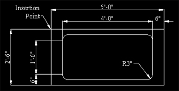
Figure 18.5.1a: Tub Figure 18.5.1c: Door36I (Interior 36" Door)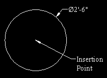
Figure 18.5.1b: Water Heater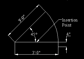
Figure 18.5.1c: Door36I (Interior 36" Door)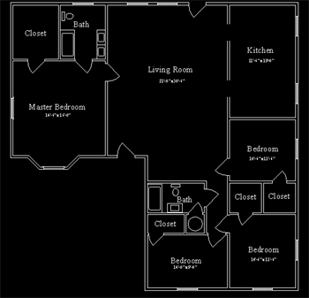
Figure 18.5.1d: Completed Drawing -
Start a new drawing from scratch.
2.1
Set the limits for a full scale drawing on an 8½" x 11" sheet of paper.
2.2
Grid: ¼"
2.3
Create the following layers (all layers use a continuous linetype):
Layer Name
Color
Battery
56
Border
5 (white)
Coil
4 (cyan)
Copperwire
3 (green)
Galvanometer
7 (white)
Pin
7 (white)
Resistor
6 (magenta)
Switch
1 (red)
Text
2 (yellow)
2.4
Use the Times New Roman font. Text sizes are ¼", 0.2", and 1/8."
2.5
Create the blocks shown in the Legend (Figure 18.5.2a). (Remember to create all blocks on layer 0.)
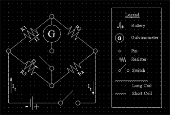
Figure 18.5.2a: My Bridge2.6
Create the drawing shown in Figure 18.5.2a (be sure to insert blocks on the appropriate layer). Save it as MyBridge in the C:\Steps\Lesson18 folder.
-
Start a new drawing from scratch.
3.1
Repeat the setup you used for Exercise 2 with the following exceptions:
3.1.1
Add a layer called Loop using color 32.
3.1.2
Grid: ½
3.1.3
Use the standard text style with ¼" and 0.2" text heights.
3.1.4
Use the battery block you created in Exercise 2 and create a block for the wire loop.
3.2
Create the ElectroMagnet Circuitry drawing shown in Figure 18.5.3a. Save it as MyMagnet in the C:\Steps\Lesson18 folder.
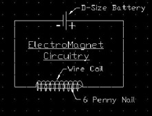
Figure 18.5.3a: ElectroMagnet Circuitry -
Using what you've learned, create the two drawings (Figures 18.5.4c & d). Use blocks whenever possible. Be sure to use appropriate layers and complete dimensioning as shown. The details shown in Figures 18.5.4a & 18.5.4b will help. Both drawings should plot on a scale of 3/8"=1'-0" on an 11" x 8½" sheet of paper. Use a title block.
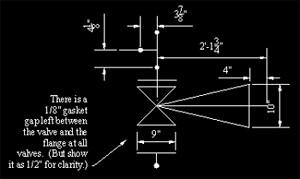
Figure 18.5.4a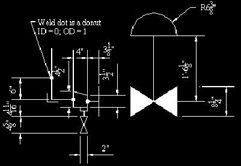
Figure 18.5.4b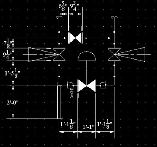
Figure 18.5.4c: Control Station #1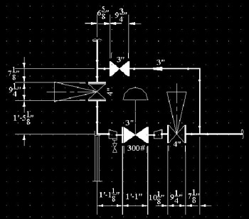
Figure 18.5.4d: Control Station #2 -
Using blocks wherever possible, create the schematic drawing shown in Figure 18.5.5a. Again, be sure to use appropriate layers. I used ½" grid marks.
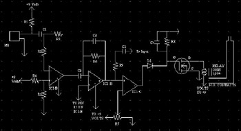
Figure 18.5.5a: Schematic -
Using blocks whenever possible, create the fireplace plans shown in Figures 18.5.6a and 18.5.6b. The grid shown on each is 1".
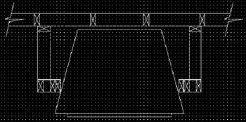
Figure 18.5.6a: Fireplace Plan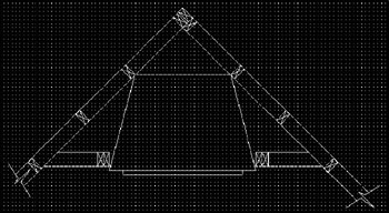
Figure 18.5.6b: Fireplace Plan
|
| < Day Day Up > |
|
EAN: 2147483647
Pages: 96