7.6 Exercises
-
Open the Checkers drawing in the C:\Steps\Lesson07 folder.
-
Using the commands you've learned in this lesson, create the drawing in Figure 7.6.1a from the objects provided. (Be sure to use different layers and colors to mark the different sides.)
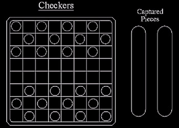
Figure 7.6.1a: -
Using the MyGrid3 template you created in Lesson 1 (or the Grid3 template in the Lesson01 folder), create the drawing in Figure 7.6.2a. Reset the grid to ¼" and the snap accordingly . Use the same layers you used in
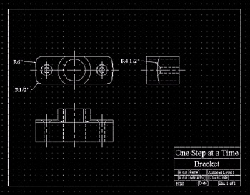
Figure 7.6.2a:Exercise #3 of Lesson 6. Don't draw the dimensions.
-
Using the following setup, create the log cabin drawing shown in Figure 7.6.3d.
4.1
Lower left limits: 0,0
4.2
Upper right limits: 36,24
4.3
Grid & Snap: [as needed]
4.4
Layers:
Layer Name
State
Color
Linetype
On
7 (white)
Continuous
Curtains
On
6 ( magenta )
Continuous
Dim
On
5 (blue)
Continuous
Gable
On
30
Continuous
Log
On
23
Continuous
Roof
On
3 (green)
Continuous
Steel
On
62
Continuous
Text
On
42
Continuous
The details are shown in Figure 7.6.3a through 7.6.3c.
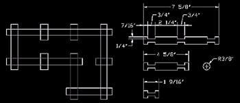
Figure 7.6.3a: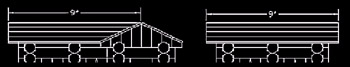
Figure 7.6.3b: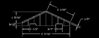
Figure 7.6.3c: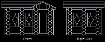
Figure 7.6.3d: -
Using what you've learned, create the drawing in Figure 7.6.4a. Create separate layers for the different objects & linetypes , and for the text. The grid is 1".
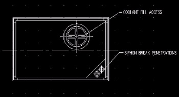
Figure 7.6.4a: Sound Shield Detail Special thanks to Alaska Diesel Electric of Seattle, Washington and Mr. Lee Pangilinan for allowing me to use this sound shield detail. -
Now create the drawings in Figures 7.6.5a through 7.6.5d. Be sure to set up the drawing limits, layers, and whatever grid and snap you think will be useful. Each drawing should be set up for plotting onto an 8 ½"x11" sheet of paper, and should be drawn to scale when dimensions are provided. (Don't draw the dimensions.)
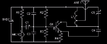
Figure 7.6.5a: Electrical Schematic 7-1 Special thanks to Michel at Ping.be for allowing me to use this detail.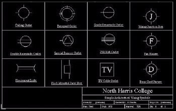
Figure 7.6.5b: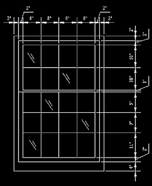
Figure 7.6.5c: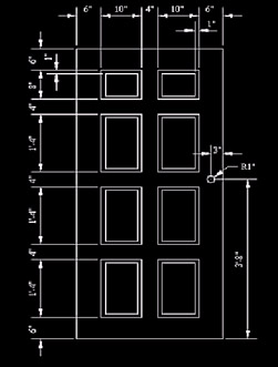
Figure 7.6.5d: