14.4 Dimension Editing: The Dimedit and DimTedit Commands
14.4 Dimension Editing: The Dimedit and DimTedit Commands
AutoCAD includes two commands for editing Associative Dimensions. These commands show a bit of overlap in their functions (redundancy again), but you will generally change or rotate the text or change the angle of the extension lines with the Dimedit command. With the DimTedit command, you can change the position of the text.
| Note | Although AutoCAD provides tools for editing Associative Dimensions, Normal Dimensions don't require any special tools. Use basic modification commands on dimensions as you would on any other objects. Edit the text using the text editing command ( DDEdit ). |
14.4.1 Position the Dimension: The DimTedit Command
The DimTedit command sequence looks like this:
Command: dimtedit (or dimted )
Select dimension: [pick the dimension to reposition]
Specify new location for dimension text or [Left/Right/Center/Home/Angle]: [pick the new position or select an option]
You can change the position of the dimension text dynamically by dragging it with the mouse, or by using AutoCAD's default Left , Right , or Center position. (Note: The Left or Right option redefines the Home position of the text next to the left or right arrow.) The Angle option allows you to rotate the dimension text, and the Home option returns the dimension text to its original position and rotation.
| Note | I realize the phrase Dimension Text Edit is confusing since the DimTedit command isn't used to edit the text but rather to edit the position of the text. Dimedit is actually used to edit the dimension text. But these are AutoCAD's terms, so we'll just have to get used to them. |
Do This: 14.4.1.1 Repositioning Dimension Text
-
Reopen the ex-base.dwg file the C:\Steps\Lesson14 folder. If you haven't completed this file, open exbase2.dwg in the same folder.
-
Follow these steps.
Tools
Command Sequence
Steps

Dimension Text Edit Button
Command: dimted
1. Enter the DimTedit command by typing dimtedit or dimted at the command prompt. Alternately, you can pick the Dimension Text Edit button on the Dimension toolbar.
Select dimension:
2. Select the dimension below the right end of the object as indicated in Figure 14.4.1.1.2a.
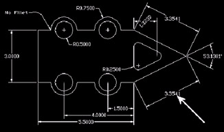
Figure 14.4.1.1.2a:Specify new location for dimension text or [Left/Right/Center/Home/Angle]: [l or r]
3. Experiment with repositioning the text using the Left and Right options. Repeat this step until you're comfortable with these options.

Command: u
4. Use the U command to return the text to its original position.
Command: dimted
Select dimension:
5. Repeat the DimTedit command and select the same dimension.
Specify new location for dimension text or [Left/Right/Center/Home/Angle]:
6. Notice that the dimension moves dynamically as you move the crosshairs. Experiment with repositioning the text manually. Repeat this step until you're comfortable with this method.
Command: [enter]
Select dimension:
7. Repeat the command and select the same dimension.

Specify new location for dimension text or [Left/Right/Center/Home/Angle]: h
8. Use the Home option to return the text to its original position.
Command: [enter]
Select dimension:
9. Repeat the command and select the same dimension.

Specify new location for dimension text or [Left/Right/Center/Home/Angle]: a
10. Tell AutoCAD to change the angle of the text
Specify angle for dimension text: 27
11. to 27 °. It now looks like Figure 14.4.1.1.11a.
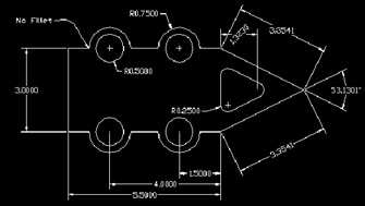
Figure 14.4.1.1.11a:
Command: qsave
12. Save the drawing.
14.4.2 Changing the Dimension Text: The Dimedit Command
The Dimedit command sequence is
Command: dimedit (or ded )
Enter type of dimension editing [Home/ New/Rotate/Oblique] <Home>: [hit enter to accept the default or tell AutoCAD what you want to do]
Select objects: [select the object(s) to change]
Notice that the Dimedit command uses a default ( <Home> ) for the initial prompt. Notice also that the option must be selected before the dimension objects (as opposed to the way DimTedit required selecting the object first).
-
Most of the options are simple. Home returns a rotated dimension to its original state. Rotate does what the Angle option did in the DimTedit command.
-
The New option presents the Multiline Text Editor with these symbols in the editing window: <> . Delete these symbols before typing the desired text. When you pick the OK button, AutoCAD will prompt to Select objects . It'll then replace the dimension text with what you've typed in the Multiline Text Editor. But be aware that once you've changed the dimension text in this manner, it'll no longer automatically adjust when the object/dimension is modified.
-
You'll find the Oblique option quite valuable when dimensioning isometrics. To dimension an isometric, you'll use the Dimaligned command, and then reposition the dimension in the correct isometric plane using this tool. (You'll see more on this in Section 14.5.)
Do This: 14.4.2.1 Changing Dimension Text
-
Be sure you're still in the ex-base.dwg file (or the ex-base2.dwg file) in the C:\Steps\Lesson14 folder.
-
Follow these steps.
Tools
Command Sequence
Steps

Dimension Edit Button
Command: ded
1. Enter the Dimedit command by typing dimedit or ded at the command prompt. Alternately, you can pick the Dimension Edit button on the Dimension toolbar.

Enter type of dimension editing [Home/ New/Rotate/Oblique] <Home>: n
2. Tell AutoCAD to edit a dimension (select the New option).
3. AutoCAD displays the Multiline Text Editor with two brackets showing ( <> ). Delete these brackets and type 4.125 .

4. Pick the OK button.
Select objects:
Select objects: [enter]
5. Select the 4.0000 dimension indicated in Figure 14.4.2.1.5a. Then complete the command.

Figure 14.4.2.1.5a:
Command: s
Select objects to stretch by crossing- window or crossing -polygon...
Select objects: Specify opposite corner: 15 found
Select objects: [enter]
Specify base point or displacement:
Specify second point of displacement or <use first point as displacement>: @1<180
6. AutoCAD replaces the dimension text with the new text. Now try stretching the object one unit to the left as shown in Figure 14.4.2.1.6a.
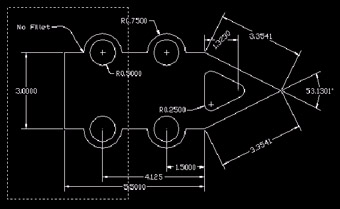
Figure 14.4.2.1.6a:7. Notice (in Figure 14.4.2.1.7a) that AutoCAD automatically updated the 5.5000 dimension but the 4.125 dimension didn't change. Remember, dimensions changed using this method are no longer Associative!
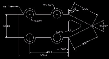
Figure 14.4.2.1.7a: Command: qsave
8. Save the drawing and exit.