14.3 And Now the Easy Way: Quick Dimensioning (QDim)
14.3 And Now the Easy Way: Quick Dimensioning ( QDim )
AutoCAD includes one of the niftiest new tools to come along in quite a while “ Quick Dimensioning ( QDim ). With QDim , you can create a string of dimensions using two picks to select the objects (with a window), one click to confirm the selection and one pick to locate the dimension. That's only four mouse clicks!
The command sequence looks like this:
Command: qdim
Select geometry to dimension: [use a window or crossing window to select the objects to dimension]
Select geometry to dimension: [hit enter to complete the selection process]
Specify dimension line position, or [Continuous/Staggered/Baseline/Ordinate/ Radius/Diameter/datumPoint/Edit/seTtings] <Continuous>: [tell AutoCAD where to place the dimension]
Most of the options are fairly obvious “ Continuous for a continuous string, Baseline for a baseline string, Ordinate for ordinate dimensions, and so forth. But let's look at the last three.
-
datumPoint allows you to define a selected point as the 0,0 coordinate of the dimension string (very handy when ordinate dimensioning).
-
Edit prompts:
Indicate dimension point to remove, or [Add/eXit] <eXit>:
Using the Edit option then, you can add or remove Extension Line Origins to the selection set.
-
seTtings prompts:
Associative dimension priority [Endpoint/Intersection] <Endpoint>:
QDim automatically dimensions to endpoints of selected objects. Using this option, you can tell AutoCAD to dimension to intersections rather than endpoints.
Let's give this nifty new tool a try.
Do This: 14.3.1 Quick Dimensions
-
Open the ex-linear2.dwg file the C:\Steps\Lesson14 folder. The drawing looks just like the exlinear.dwg file we used in Exercise 14.2.1.1.
-
Follow these steps.
Tools
Command Sequence
Steps

Quick Dimension Button
Command: qdim
1. Enter the QDim command or pick the Quick Dimension button on the Dimension toolbar.
Select geometry to dimension:
2. Use a crossing window to select the bottom line, the slot, and the large circle. Don't select anything else (see Figure 14.3.1.2a).
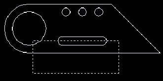
Figure 14.3.1.2a:Select geometry to dimension:
3. Hit enter to confirm the selection set.
Specify dimension line position, or
[Continuous/Staggered/ Baseline/Ordinate/ Radius/Diameter/ datumPoint/Edit/seTtings] <Continuous>:
4. Locate the dimension below the object (Figure 14.3.1.4a).
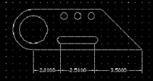
Figure 14.3.1.4a: Command: [enter]
5. Now let's try a baseline dimension. Repeat the command.
Select geometry to dimension:
6. Use a crossing window to select the upper line and the four circles as shown in Figure 14.3.1.6a.
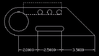
Figure 14.3.1.6a:Select geometry to dimension: [enter]
7. Hit enter to confirm the selection set.
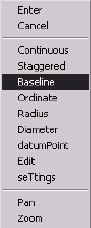
Specify dimension line position, or
[Continuous/Staggered/ Baseline/ Ordinate/Radius/ Diameter/datumPoint/ Edit/ seTtings] <Continuous>: b
8. Tell AutoCAD to create a Baseline dimension.
Specify dimension line position, or
[Continuous/Staggered/Baseline/ Ordinate/ Radius/Diameter/ datumPoint/Edit/seTtings] <Baseline>:
9. Locate the dimensions as shown in Figure 14.3.1.9a.
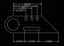
Figure 14.3.1.9a:Command: quit
10. Exit the drawing without saving.
Doesn't that make you wonder why we ever did it any other way?
Still, by now, you may have noticed that dimensions don't always appear just the way we think they should. And sometimes (God forbid ), the dimension
has to change to accommodate some new design information. Our next section will show you how to modify dimensions.