14.2 Dimension Creation: Dimension Commands
14.2.1 Linear Dimensioning
One of the first things I tell my students when we study dimensions is to use the Dimension toolbar whenever possible. AutoCAD's dimension commands can be difficult to remember, but the toolbar has pictures to show what each does. I suggest activating the Dimension toolbar and docking it above the graphics area (see Lesson 1 if you need help).
The workhorse of AutoCAD dimensioning is the Dimlinear command. It'll draw all the straight horizontal and vertical dimensions. The command sequence is
Command: Dimlinear (or dli )
Specify first extension line origin or <select object>: [select the first dimension point]
Specify second extension line origin: [select the second dimension line origin]
Specify dimension line location or [Mtext/ Text/Angle/Horizontal/Vertical/Rotated]: [locate the dimension line]
Dimension text = X.XXXX [AutoCAD reports the dimension value and places the dimension]
-
The first option AutoCAD presents is easily missed. AutoCAD prompts for the First extension line origin . Most users stop there, select the First and Second extension line origins and proceed with the dimension. But the second part of that first prompt reads or <select object> . This option allows you to simply select an object to dimension. If you press enter and select an object, AutoCAD determines where the object's endpoints lie and places the extension lines accordingly .
The next set of options occurs after the extension line origins are located.
-
AutoCAD will automatically determine if the dimension should be Horizontal or Vertical by the location of the crosshairs. However, you can override AutoCAD's determination by typing H or V .
-
The Text and MText options allow you to override AutoCAD's automatic determination of the actual dimension.
The dimension won't automatically update if you override here. I don't recommend doing this as it defeats the purpose of Associative Dimensioning. (Note: The MText prompt won't appear if Associative Dimensioning is turned off.)
-
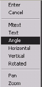
The Angle option allows you to rotate the dimension text for a better fit (Figure 14.2.1a). This handy tool is far too often overlooked.
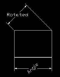
Figure 14.2.1a: -
The Rotated option allows you to measure a dimension at an angle to the object other than 90 °. (See Figure 14.2.1a for a comparison of the Angle and Rotated options.)
Let's look at the Dimlinear command.
| Note | All of the commands in this lesson can be found in the Dimension pull-down menu. |
Do This: 14.2.1.1 Linear Dimensioning
-
Open the Ex-Linear.dwg file the C:\Steps\Lesson14 folder. The drawing looks like Figure 14.2.1.1a.

Figure 14.2.1.1a: -
Follow these steps.
Tools
Command Sequence
Steps

Dimlinear Button
Command: dli
1. Enter the Dimlinear command by typing dimlinear or dli at the command prompt. Alternately, you can pick the Linear Dimension button on the Dimension toolbar.
Specify first extension line origin or <select object>: _cen of
2. Pick the center of the circle at Point 1 (Figure 14.2.1.1.2a)
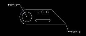
Figure 14.2.1.1.2a:Specify second extension line origin: _endp of
3. then the endpoint at Point 2.
Specify dimension line location or
[Mtext/Text/Angle/Horizontal/Vertical/ Rotated]:
Dimension text = 8.0000
4. Locate the dimension line four grid points below the bottom line of the object (Figure 14.2.1.1.4a.
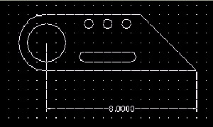
Figure 14.2.1.1.4a: Command: [enter]
5. Repeat the Dimlinear command.
Specify first extension line origin or <select object>: [enter]
6. Let's use the select object option. Hit enter .
Select object to dimension:
7. Select the angled line on the right end of the object.
Specify dimension line location or
[Mtext/Text/Angle/Horizontal/Vertical/ Rotated]:
Dimension text = 3.0000
8. Pick a point four grid points to the right (Figure 14.2.1.1.8a).
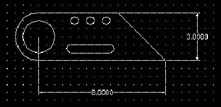
Figure 14.2.1.1.8a:
Command: qsave
9. Save the drawing but don't exit.
14.2.2 Dimensioning Angles
Our next dimension command is Dimangular . You'll use this to dimension angles as well as for angular dimensions on circles and arcs. The command sequence for dimensioning an arc or circle is
Command: Dimangular (or dan )
Select arc, circle, line, or <specify vertex>: [show AutoCAD what you want to
dimension or hit enter to select the vertex first]
Specify second angle endpoint: [this prompt appears only if a circle is being dimensioned]
Specify dimension arc line location or [Mtext/Text/Angle]: [locate the dimension line]
Dimension text = [AutoCAD reports and places the dimension]
If you select a line at the first prompt, AutoCAD prompts:
Select second line:
You must select a line that forms an angle with the first selected line, and then locate the dimension as prompted.
If you opt to select the vertex first, AutoCAD prompts:
Specify angle vertex: [select the vertex]
Specify first angle endpoint: [select a point on the first line]
Specify second angle endpoint: [select a point on the second line]
The MText , Text , and Angle options are the same as in the Dimlinear command.
Let's look at the Dimangular command.
Do This: 14.2.2.1 Dimensioning Angles
-
Be sure you're in the Ex-Linear.dwg file the C:\Steps\Lesson14 folder. If not, please open it now.
-
Follow these steps.
Tools
Command Sequence
Steps

Angular Dimension Button
Command: dan
1. Enter the Dimangular command by typing Dimangular or dan at the command prompt. Alternately, you can pick the Angular Dimension button on the Dimension toolbar.
2. Select the arc on the left end of the object.
3. Place the dimension at the end of the bottom linear dimension as shown in Figure 14.2.2.1.3a.
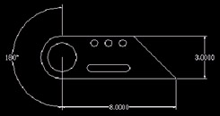
Figure 14.2.2.1.3a: Command: [enter]
4. Now let's dimension the angle at the other end of the object. Repeat the command.
Select arc, circle, line, or <specify vertex>:
5. Select the bottom line on the object
Select second line:
6. then the angled line.
Specify dimension arc line location or [Mtext/Text/Angle]:
Dimension text = 45
7. Notice that the angle changes as you change the cursor position. Place the dimension line at the bottom arrow of the vertical dimension (Figure 14.2.2.1.7a).
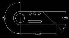
Figure 14.2.2.1.7a:
Command: qsave
8. Save the drawing but don't exit.
14.2.3 Dimensioning Radii and Diameters
Very little difference separates dimensioning radii and dimensioning diameters. In fact, the command sequences are identical:
Command: dimradius (or dra ) [OR dimdiameter (or ddi )]
Select arc or circle: [show AutoCAD what you want to dimension]
Dimension text = [AutoCAD reports the dimension]
Specify dimension line location or [Mtext/ Text/Angle]: [locate the dimension]
AutoCAD will automatically place either a diameter symbol ( ˜ ) or an R in front of the dimension to indicate what has been dimensioned.
Do This: 14.2.3.1 Dimensioning Diameters and Radii
-
Be sure you're in the Ex-Linear.dwg file the C:\Steps\Lesson14 folder. If not, please open it now.
-
Follow these steps.
Tools
Command Sequence
Steps

Command: e
1. Erase the 180 ° arc dimension.

Radius Dimension Button
Command: dra
2. Enter the Dimradius command by typing dimradius or dra at the command prompt. Alternately, you can pick the Radius Dimension button on the Dimension toolbar.
3. Select the arc at the left end of the object.
4. Locate the dimension as shown in Figure 14.2.3.1.4a.
Notice that AutoCAD places the dimension and a Center Mark locating the center of the arc being dimensioned.
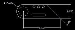
Figure 14.2.3.1.4a:
Diameter Dimension Button
Command: ddi
5. Enter the Dimdiameter command by typing dimdiameter or ddi at the command prompt. Alternately, you can pick the Diameter Dimension button on the Dimension toolbar.
Select arc or circle:
6. Select the large circle to the left inside the object.
Dimension text = 2.0616
Specify dimension line location or [Mtext/ Text/Angle]:
7. Place the dimension as shown in Figure 14.2.3.1.7a.
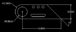
Figure 14.2.3.1.7a: Command: qsave
8. Save the drawing but don't exit.
14.2.4 Dimension Strings
It's often preferable to string dimensions. This makes it easier for the contractor to find and read dimensions, and it enhances the overall appearance of the drawing.
To string dimensions, we can repeat the Dimlinear command over and over, or we can begin our string with the Dimlinear command and then follow it with the Dimcontinue command. The Dimcontinue command will place dimensions along the same line begun by the Dimlinear command. With each selection, the second extension line from the previous dimension is used as the first extension line for the continued string. Some of the many benefits of this approach include:
-
Not overwriting the extension line. Too many lines atop one another may cause plotting problems later.
-
You don't have to locate the dimension line with each new selection. AutoCAD simply continues along the previous string.
-
The command automatically repeats until you stop it. This saves the time required to repeat the command.
The command sequence is
Command: dimcontinue (or dco )
Specify a second extension line origin or [Undo/Select] <Select>: [simply select the origin of the second extension line; AutoCAD assumes the first extension line origin to be the second extension line of the last dimension entered]
Dimension text = [AutoCAD reports the dimension]
Specify a second extension line origin or [Undo/Select] <Select>: [AutoCAD repeats the command until you hit enter to exit]
Select continued dimension: [when you hit enter at the last prompt, AutoCAD will provide the opportunity to select a different dimension from which to continue; hitting enter at this prompt will exit the command]
Do This: 14.2.4.1 String Dimensions
-
Be sure you're in the Ex-Linear.dwg file the C:\Steps\Lesson14 folder. If not, please open it now.
-
Follow these steps.
Tools
Command Sequence
Steps
Command: dli
1. Create a linear dimension between the center of the larger circle and the center of the leftmost arc on the slot (Figure 14.2.4.1.1a). Be sure to select the circle first.
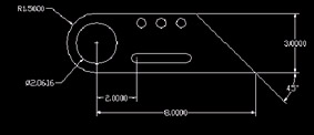
Figure 14.2.4.1.1a:
Continue Dimension Button
Command: dco
2. Enter the Dimcontinue command by typing Dimcontinue or dco at the command prompt. Alternately, you can pick the Continue Dimension button on the Dimension toolbar.
Specify a second extension line origin or [Undo/Select] <Select>: _cen of
Dimension text = 2.5000
3. Select the center of the arc on the other end of the slot.
Specify a second extension line origin or [Undo/Select] <Select>: [enter]
Select continued dimension: [enter]
4. Hit enter twice to complete the command. Your drawing looks like Figure 14.2.4.1.4a.
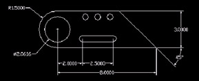
Figure 14.2.4.1.4a: Command: dli
Specify first extension line origin or <select object>: _cen of [middle small circle]
Specify second extension line origin: _cen of [left small circle]
5. Now let's use what we know to dimension the upper circles. Put a linear dimension between the two left smaller circles (pick the middle one first).
Specify dimension line location or
[Mtext/Text/Angle/Horizontal/Vertical/ Rotated]: a
Specify angle of dimension text: 60
Specify dimension line location or
[Mtext/Text/Angle/Horizontal/Vertical/ Rotated]:
Dimension text = 1.0000
6. Angle the dimension at 60 °. Then place the dimensions as shown in Figure 14.2.4.1.6a.
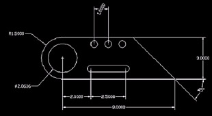
Figure 14.2.4.1.6a: Command: dco
Specify a second extension line origin or [Undo/Select] <Select>: _cen of
Dimension text = 2.2500
7. Continue the dimension to the center of the large circle.
Specify a second extension line origin or [Undo/Select] <Select>: [enter]
8. We want to continue the dimension in the other direction now, so hit enter to go to the Select continued dimension: prompt.
Select continued dimension:
9. Select the right extension line (above the smaller middle circle).
Specify a second extension line origin or [Undo/Select] <Select>: _cen of
Dimension text = 1.0000
10. Select the center of the smaller right circle.
Specify a second extension line origin or [Undo/Select] <Select>: [enter]
Select continued dimension: [enter]
11. Exit the command. Your drawing looks like Figure 14.2.4.1.11a.
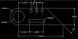
Figure 14.2.4.1.11a:12. Now complete the dimensioning as shown in Figure 14.2.4.1.12a.
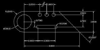
Figure 14.2.4.1.12a: Command: qsave
13. Save the drawing and exit.
14.2.5 Aligning Dimensions
Nonlinear objects often require nonlinear dimensioning. This usually means that the dimension must be aligned with the object for clarity.
The Dimaligned command works almost like the Dimlinear command. The difference is that the aligned dimension parallels the first and second extension line origins.
The command sequence is
Command: dimaligned (or dal )
Specify first extension line origin or <select object>: [select the first dimension point]
Specify second extension line origin: [select the second dimension point]
Specify dimension line location or
[Mtext/Text/Angle]: [locate the dimension line]
Dimension text = [AutoCAD reports and places the dimension]
The options are identical to those used in the Dimlinear command.
Do This: 14.2.5.1 Aligned Dimensions
-
Open the ex-base.dwg file the C:\Steps\Lesson14 folder. The drawing looks like Figure 14.2.5.1a.
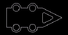
Figure 14.2.5.1a: -
Follow these steps.
Tools
Command Sequence
Steps

Aligned Dimension Button
Command: dal
1. Enter the Dimaligned command by typing dimaligned or dal at the command prompt. Alternately, you can pick the Aligned Dimension button on the Dimension toolbar.
Specify first extension line origin or <select object>: [enter]
2. Hit enter to select the object to dimension.
Select object to dimension:
3. Select the upper angled line on the right end of the object.
Specify dimension line location or
[Mtext/Text/Angle]:
Dimension text = 3.3541
4. Locate the dimension line three grid points above the object (Figure 14.2.5.1.4a).
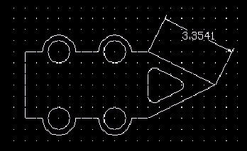
Figure 14.2.5.1.4a: Command: [enter]
5. Repeat the command.
Specify first extension line origin or <select object>: [enter]
Select object to dimension:
Specify dimension line location or
[Mtext/Text/Angle]:
Dimension text = 3.3541
6. Place a dimension for the lower angled line as shown in Figure 14.2.5.1.6a.
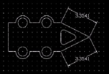
Figure 14.2.5.1.6a: Command: qsave
7. Save the drawing but don't exit.
14.2.6 Baseline Dimensions
Like the Dimcontinue command, Dimbaseline works from an original linear dimension. But where continued dimensions were based on the second extension line origin of the last or selected linear dimension, the baseline dimension starts from the same f i rst extension line origin of the last or selected linear dimension.
The command sequence parallels that of the Dimcontinue command as well.
Command: dimbaseline (or dba )
Specify a second extension line origin or [Undo/Select] <Select>: [select the origin of the second extension line “ AutoCAD assumes the first extension line origin to be the first extension line of the last dimension entered]
Dimension text = [AutoCAD reports and inserts the dimension]
Specify a second extension line origin or [Undo/Select] <Select>: [AutoCAD repeats the prompt until you hit enter to exit]
Select base dimension: [when you hit enter at the last prompt, AutoCAD will provide the opportunity to select a different dimension from which to base the baseline dimensions; hitting enter at this prompt will exit the command]
Let's try a baseline dimension.
Do This: 14.2.6.1 Baseline Dimensions
-
Be sure you're still in the ex-base.dwg file the C:\Steps\Lesson14 folder. If not, please open it now
-
Follow these steps.
Tools
Command Sequence
Steps
Command: dla
1. Draw a linear dimension as shown in Figure 14.2.6.1.1a. Be sure to select the extension line origin on the right first.
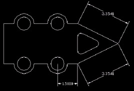
Figure 14.2.6.1.1a:
Baseline Dimension Button
Command: dba
2. Enter the Dimbaseline command by typing dimbaseline or dba at the command prompt. Alternately, you can pick the Baseline Dimension button on the Dimension toolbar.
Specify a second extension line origin or [Undo/Select] <Select>: _cen of
Dimension text = 4.0000
3. Pick the center of the next bolt hold to the left. AutoCAD reports and places the dimension.
Specify a second extension line origin or [Undo/Select] <Select>: _endp of
Dimension text = 5.5000
4. Pick the lower left endpoint of the object.
Specify a second extension line origin or [Undo/Select] <Select>: [enter]
Select base dimension: [enter]
5. Hit enter twice to exit the command. Your drawing looks like Figure 14.2.6.1.5a
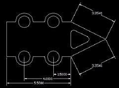
Figure 14.2.6.1.5a: Command: qsave
6. Save the drawing but don't exit.
14.2.7 Placing Leaders
Use the QLeader command to place simple callouts that require an arrow or line to reference an object.
Contrary to the way we learned to place callouts in board drafting, CAD leaders should be placed before the callout text. Here is the sequence:
Command: qleader (or le )
Specify first leader point, or [Settings] <Settings>: [pick the place where you want the tip of the arrow]
Specify next point: [pick the outer end of the first leader line]
Specify next point: [pick the end of the second leader line]
Specify text width <0.0000>: [you can specify the width of the desired text; hitting enter at this prompt allows for unrestricted width]
Enter first line of annotation text <Mtext>: [place your callout text “ hit enter twice at the end of your text string to exit the command; if the callout requires more than one line, you can hit enter before adding text to call the Multiline Text Editor]
There are several options associated with the QLeader command. Luckily, AutoCAD has placed them in a user -friendly dialog box ( 14.2.7a).
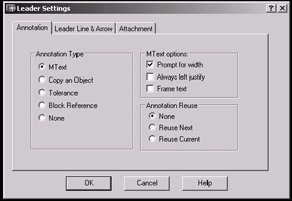
Figure 14.2.7a:
Access the dialog box via the Settings option at the first QLeader prompt (just hit enter). Notice the three tabs. We'll look at each beginning with the default “ Annotation .
-
Three frames compose the Annotation tab:
-
Use the Annotation Type frame to determine what to place after the leader:
-
MText is simply the standard text entry.
-
Copy an Object allows you to copy text or an object from one part of the drawing to the end of the leader line.
-
We'll discuss Tolerance in more detail in Lesson 15.
-
Block Reference allows you to place a block at the end of the leader line. (We'll see more on blocks in Lessons 18 and 19).
-
None , of course, allows you to create a leader without text. Use this option when the callout has already been placed on the drawing (as you did on the board).
-
-
The MText options frame provides three options:
-
Prompt for width causes AutoCAD to prompt for the width of the MText entry (much like the MText command does).
-
Always left justify can be a nuisance. by default, AutoCAD will determine the text justification depending on which way the leader line goes.
-
Frame text will place a frame around the leader text.
-
-
-
The Leader Line & Arrow tab (Figure 14.2.7b) presents four frames of options.
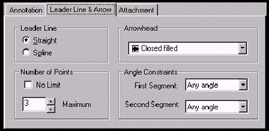
Figure 14.2.7b:-
The Leader Line frame allows you to use the standard ( Straight ) leader line or a fancier Spline line.
-
The Arrowhead frame contains a control box from which you may select the type of arrowhead (or no arrowhead at all) to use on the leader.
-
Number of Points refers to the number of points allowed to define the leader line. The default (3) means that you can draw a leader with two lines. A check in the No Limit check box removes all limitations on the number of lines your leader can have.
-
Angle Constraints defines how the leader may be drawn. I prefer the default Any angle for the first segment; but then I require the second segment to be Horizontal to lead into the text.
-
-
The last tab “ Attachment (Figure 14.2.7c) “ allows you to position the text in relation to the leader line.
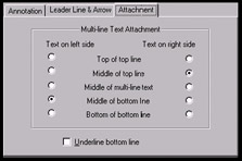
Figure 14.2.7c:
The number of options for the QLeader command reflects the importance of leaders in drafting. No one preference can be universal “ although the defaults come fairly close. So you should become familiar with the Leader Settings dialog box.
Let's draw some leaders.
Do This: 14.2.7.1 Leaders
-
Be sure you're still in the ex-base.dwg file the C:\Steps\Lesson14 folder. If not, please open it now
-
Follow these steps.
Tools
Command Sequence
Steps

Quick Leader Button
Command: le
1. Enter the QLeader command by typing qleader or le at the command prompt. Alternately, you can pick the Quick Leader button on the Dimension toolbar.
Specify first leader point, or [Settings] <Settings>: [enter]
2. Hit enter to access the Leader Settings dialog box.
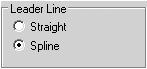
3. On the Leader Line & Arrow tab, change the Leader Line to use a Spline .
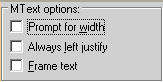
4. On the Annotation tab, clear the check box next to Prompt for width .

5. Pick the OK button to exit the dialog box.
Specify first leader point, or [Settings] <Settings>:
Specify next point:
Specify next point:
6. Place the leader as shown in Figure 14.2.7.1.6a.

Figure 14.2.7.1.6a:Enter first line of annotation text <Mtext>: No Fillet
Enter next line of annotation text: [enter]
7. Type in the text indicated in Figure 14.2.7.1.7a, then exit the command.

Figure 14.2.7.1.7a: Command: qsave
8. Save the drawing but don't exit.
9. Complete the dimensions as shown in Figure 14.2.7.1.9a.
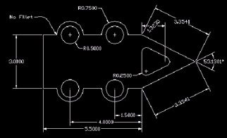
Figure 14.2.7.1.9a: Command: qsave
10. Save and close the drawing.
14.2.8 Ordinate Dimensions
Ordinate dimensioning is a valuable tool in some types of manufacturing. Dimordinate places a dimension that is actually a distance from the 0,0 coordinate of the drawing. To be useful then, 0,0 must be located somewhere on the object itself (usually the lower left corner).
The command sequence for the Dimordinate command is
Command: dimordinate (or dor )
Specify feature location: [select the feature to be dimensioned]
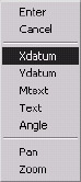
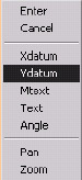
Specify leader endpoint or [Xdatum/ Ydatum/Mtext/Text/Angle]: [you can specify the X or Y distance from 0,0 or identify the datum by mouse movement]
Dimension text = [AutoCAD reports and places the distance]
-
As indicated, you can specify an Xdatum (X- distance from 0,0) or a Ydatum (Y-distance from 0,0) by selecting that option.
-
If you prefer to place Text or MText at the ordinate location, those options are also available.
-
The Angle option behaves just as it does on other dimension tools “ that is, you may define the angle of the dimension text.
Let's try an exercise.
Do This: 14.2.8.1 Ordinate Dimensioning
-
Open the ex-ordinate.dwg file the C:\Steps\Lesson14 folder. The drawing looks like Figure 14.2.8.1a.
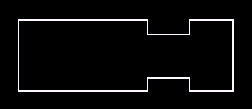
Figure 14.2.8.1a:(Note: First we'll use the UCS command to relocate the 0,0 coordinate of the drawing. For more details on the UCS command, see our next text, 3D AutoCAD 2004: One Step at a Time .)
-
Follow these steps.
Tools
Command Sequence
Steps
Command: ucs
1. Enter the UCS command by typing ucs at the command prompt.
Enter an option [New/Move/orthoGraphic/ Prev/ Restore/Save/Del/Apply/?/World]
<World>: n
2. At the prompt, tell AutoCAD to create a New UCS.
Specify origin of new UCS or [ZAxis/3point/ OBject/Face/ View/X/Y/Z] <0,0,0>: _int of
3. AutoCAD asks where to place the new origin. (It's allowing you to redefine the 0,0 coordinate of the drawing “ a useful thing in 3- dimensional drawing.)
Pick the lower left intersection of the object (use OSNAPs).

Ordinate Dimension Button
Command: dor
4. Enter the Dimordinate command by typing dimordinate or dor at the command prompt. Alternately, you can pick the Ordinate Dimension button on the Dimension toolbar.
Specify feature location:_endp of
5. Select the left side of the lower indentation (Figure 14.2.8.1.6a).
Specify leader endpoint or [Xdatum/ Ydatum/Mtext/Text/ Angle]:
Dimension text = 4.5000
6. Pick a point two grid marks due south of the point selected in Step 5. Your drawing looks like Figure 14.2.8.1.6a.
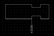
Figure 14.2.8.1.6a: Command: [enter]
7. This time, specify the datum you'll use. Repeat the Dimordinate command.
Specify feature location:_endp of
8. Select the lower right corner of the object.
Specify leader endpoint or [Xdatum/ Ydatum/Mtext/Text/ Angle]: x
9. Tell AutoCAD that you want an Xdatum .
Specify leader endpoint or [Xdatum/ Ydatum/Mtext/Text/ Angle]:
10. Select a point two grid marks south and two grid marks west (Figure 14.2.8.14a). (Toggle Ortho off to make this easier.)
Command: [enter]
11. Repeat the command.
Specify feature location:_endp of
12. Select the same point selected in Step 8.
Specify leader endpoint or [Xdatum/ Ydatum/Mtext/Text/ Angle]: y
13. Tell AutoCAD that you want a Ydatum .
Specify leader endpoint or [Xdatum/ Ydatum/Mtext/Text/ Angle]:
Dimension text = 0.0000
14. Select a point two grid marks east and two grid marks north. Your drawing looks like Figure 14.2.8.1.14a.
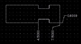
Figure 14.2.8.1.14a:15. Complete the drawing as shown in Figure 14.2.8.1.15a.
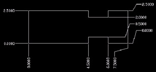
Figure 14.2.8.1.15a: Command: qsave
16. Save and close the drawing.
- ERP Systems Impact on Organizations
- ERP System Acquisition: A Process Model and Results From an Austrian Survey
- The Effects of an Enterprise Resource Planning System (ERP) Implementation on Job Characteristics – A Study using the Hackman and Oldham Job Characteristics Model
- Distributed Data Warehouse for Geo-spatial Services
- Intrinsic and Contextual Data Quality: The Effect of Media and Personal Involvement