The Data Diagram Editor
Another way to view your data components is to use the Data Diagram page, which is a subpage of the tab for the unit that represents the Data Module in the Source Code Editor. This page is little known because its documentation is squirreled away deep in the help. But a search in the Help index for Data Module Designer, followed by double-clicking it, will give you a set of topics that include the Data Diagram editor.
Figure 7.3 shows a sample diagram in that window.
Figure 7.3. A data diagram.
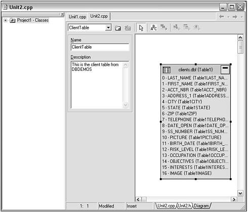
This shows the table from the data module (added to the diagram by dragging it from the tree view to the diagram view ”note that this is the only way to add components to the diagram), and its persistent fields. With a more complex data module it can show their relationships (for instance, a lookup field and a master/detail relationship are automatically generated in the diagram).
As you change components (adding or removing fields, changing properties, attaching them to new data sources, or even deleting a component), those changes will be reflected in the diagram ”at least for the components that have been dragged into the diagram.
Components can be removed from the diagram with Delete, and each object has a pop-up menu that can be used for things like invoking the fields editor on a table or running the SQL Explorer to see details about the table. Connections between components also have a pop-up menu that can, among other things, be used to remove the relationship represented by the connection.
Note that you are not limited to using data components in the diagram ”components such as TTimer and your own custom components can be dragged into the diagram.
The Data Diagram editor has several buttons on the top. From left to right, they are
-
Select ” Enables you to point at and select diagram objects.
-
Comment ” The yellow comment block enables you attach notes to any diagram components. To edit the comment, simply double-click it and type. Pressing Esc abandons any changes in progress. To complete the editing, just click outside the comment.
-
Allude Connector ” Allows you to connect the comments to the relevant components in the diagram. Drag between the comment and the component receiving the comment or vice versa. Any number of components can share a comment. A comment can also point to any number of components.
-
Property Connector ” Enables you to show a link between the property of one component and the component that property references. If you use this between two components not yet connected, the designer determines the intended property assignment and automatically fills in the property with the appropriate link. To use this, click the button and drag from the referencing component to the referenced component.
-
Master/Detail Connector ” Enables you to connect two data sets in a master/detail relationship. To use this, click the button and drag from the master to the detail data set. The field link editor will appear and allow you to specify the relationship.
-
Lookup Connector ” Enables you to set up a lookup field between two tables. As with the Master/Detail, drag from the data set that will contain the lookup field to the data set that contains the data to be looked up. The lookup field editor dialog will appear and allow you to specify the lookup field.
Unfortunately, you cannot zoom out of a Data Diagram to see it as a whole. However, you can print it, and you can scroll around in it as needed.
Finally, note that the data diagram does not participate in form inheritance, so when you create a descendant data module, you do not get a copy of the ancestor 's diagram. That means you must either recreate the diagram in the descendant or only document the descendant's components.
| |
| Top |