The IP
| The Internet Protocol is the basis on which the Internet operates. Together with protocols at other layers, the IP layer provides communications for countless applications. IP is a connectionless protocol providing layer 3 routing functions. IP Addressing and SubnettingAs you already know, but I feel compelled to write, IP addresses for version 4 of IP consist of four 32-bit numbers separated by periods, known as the "dotted quad" or "dotted decimal" notation. Although seemingly everyone understands or at least has seen an IP address, it certainly seems as though fewer and fewer understand subnetting and the subnet masks that are an important part of the IP addressing scheme. This section briefly looks at IP addressing and subnetting. IP addresses are divided into different classes rather than being an entirely flat address space. The classes for IP addresses are shown in Table 1.1.
In practice, only addresses in Classes A through C are for general Internet use. However, some readers may have experience with Class D addresses, frequently used for multicast. Class E is the experimental and unallocated range.
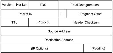
The IP header consists of a number of fields and totals 20 bytes, not including optional option fields that can be included as part of the header. The IP header is shown in Figure 1.2. Figure 1.2. The IP header.
The IP header begins with 4 bits indicating the version, currently version 4, followed by the length of the header, which is normally 20 bytes plus optional options. The maximum length of the IP header is 60 bytes. The next field, type-of-service or TOS, contains 3 bits for precedence (not used), 4 bits for the TOS itself, and one bit that must be set to 0. These are the four possible values for TOS:
Under normal conditions these 4 bits are all zero, but certain applications might use various bits depending on their needs. For example, an SSH session might set the minimize delay bit because it is interactive by nature. The first number of an IP address indicates the class of the address. Because each number within the dotted decimal notation is 8 bits, the possible values for each number are 0 tHRough 255. The class indicates the default number of bits devoted to the network portion of the address versus the number of bits devoted to the host identification with a given address. The division between the network portion of the address versus the host portion of the address is important because it is the basis of subnet addressing. Aside from classes, there are three types of addresses available on the Internet: unicast, multicast, and broadcast. Unicast addresses correspond to a single host on the Internet. Multicast addresses correspond to a group of hosts that ask to be included within that group. Broadcast addresses are used by hosts that want to send data to every host on a given subnet. Each class of address has a default subnet mask that indicates the division between the network and host portion of a given address. That's quite a mouthful, so I'll give examples and then there will be a quiz later. Kidding! The default subnet masks for Classes A through C are given in Table 1.2.
You've undoubtedly seen and typed these numbers when configuring network settings. As previously stated, the subnet mask indicates the division between the network and the host portions of an IP address. The unmasked portion, known as the host portion, of the address comprises the logical network on which a given host resides. In other words, with a Class C subnet mask of 255.255.255.0, there can be a total of 254 hosts on the network. An astute reader might notice that there are really 256 addresses but only 254 hosts. Within a given logical IP network there are two special addresses, the network address and the broadcast address. This is true regardless of the size of the network. In the case of the Class C subnet example, the network address ends with .0 and the broadcast address ends with .255. As Table 1.2 illustrates, of the total 32 bits in an IPv4 address, a Class A subnet mask uses 8 bits, a Class B subnet mask uses 16 bits, and a Class C subnet mask uses 24 bits. When a network is divided along traditional address Class boundaries using the default subnet mask, it is said to be a classful network. As you might expect, there are times when it would be beneficial to use a much smaller network. For example, two IP routers that only need to transmit between each other would use an entire Class C network using traditional classful subnetting. Luckily, classless subnetting is also possible. Using classless subnetting, officially called Classless Inter Domain Routing (CIDR), you can divide networks according to need by adding or subtracting bits from the subnet mask. This is useful for conservation of addresses because it enables the network administrator to customize the size of the network based more on need and convenience than on the classful boundaries. Jumping back to the example with two routers that communicate solely with each other, using CIDR a network administrator can create a network of just two hosts with the resulting subnet mask being 255.255.255.252. I'll carry that example a little further. The two routers only need to talk to each other within this network so that they can route traffic between two different IP networks. The network administrator assigns one router the address 192.168.0.1 and the other router 192.168.0.2 and gives both a subnet mask of 255.255.255.252. Given that subnet mask, there are two available IP addresses with which a host could be addressed. The network address for this logical network is 192.168.0.0 and the broadcast address is 192.168.0.3. Using CIDR, the network administrator can now use the remainder of the 192.168.0 network, following CIDR rules, for other hosts. You'll frequently see subnet notation referred to with a /NN with NN being the number of bits to be masked. For example, a Class C has 24 bits for the network portion of the address, which means that it could be referred to as a /24. A Class B would be /16 and a Class A would be /8. Going back to the two-router example, the CIDR notation for this address is /30 because 30 bits of the address are consumed by the subnet. Why is subnetting important? The simple answer is that a subnet defines the largest possible broadcast space for a given network. Within a given subnet a host can send a broadcast to all other hosts in that subnet. In practice, though, broadcasts are limited more by physical limitations than by the logical limitations presented by subnet masks. You can connect only so many devices to a switch before you may (I repeat, may) start to see performance degradation and would likely divide the network into smaller logical sections. Without subnetting we would have a very large, flat address space, which would be much slower than the hierarchical addressing currently used. IP FragmentationThere are times when an IP datagram is larger than the maximum allowed size for the physical medium on which it will be traveling. This maximum allowed size is known as the Maximum Transmission Unit, or MTU. If an IP datagram is larger than the MTU for the medium, the datagram will need to be split into smaller chunks before being transmitted. For Ethernet, the MTU is 1500 bytes. The process of splitting an IP datagram into smaller pieces is called fragmentation. Fragmentation is handled at the IP layer of the OSI model and is thus transparent to higher layer protocols such as TCP and UDP. As an administrator, you should care about fragmentation insofar as it can affect application performance if one of the fragments of a large segment gets lost. In addition, as a security administrator, you should understand fragmentation because it has been a path for attack in the past. Realize, however, that any intermediary router or other devices within the communication path may cause fragmentation and you may not even know it. Broadcasting and MulticastingWhen a device wants to send data to other devices on the same network segment, it can send the data to a special address known as a broadcast address to accomplish this task. On the other hand, a multicast is sent to the devices that belong to the multicast group, sometimes called subscribers. Imagine a large, flat network in which every computer and device is connected to the others. In such an environment every network device sees every other network device's traffic. In this type of network, each device sees the traffic and determines whether it cares about the traffic in question. In other words, it looks to see whether the data is addressed to it or to another device. If the data is addressed to the device, it passes the data up to the layers of the OSI model. At the interface level for Ethernet, the device looks for its MAC address or the hardware address associated with the network interface itself. Remember that IP addresses are relevant only to protocols at higher layers on the OSI model. Aside from frames addressed to the device itself, two special cases exist that might cause an interface to accept data and pass it up to higher layers. These two special cases are multicast and broadcast. Multicast is a method for transmitting data to a subset of devices that are said to be subscribed to that multicast. On the other hand, broadcasts are meant to be processed by every device that receives them. Primarily two types of broadcasts are available: directed broadcast and limited broadcast. By far, directed broadcasts are the most common. Limited broadcasts are used by devices attempting to configure themselves through DHCP, BOOTP, or another configuration protocol. A limited broadcast is sent to the address 255.255.255.255 and should never pass through a router. This is a key hint for anyone who controls a router or other routing device such as a routing firewall. If you receive a packet on your external, Internet-facing router interface addressed to 255.255.255.255, chances are that there is a misconfigured device or, more likely, that a potential attacker is attempting to probe your network. You may see a limited broadcast on an internal interface for a router if you have devices that configure themselves on boot using DHCP. Directed broadcasts are the most common form of broadcast you'll see on any given network. This is because broadcasts are used by the Address Resolution Protocol (ARP, discussed later) to determine the MAC address for an IP address on a given subnet. A directed broadcast is a broadcast that is limited by the network or subnet in which the sending device resides. By default, when a router interface encounters a directed broadcast, it does not pass it along to other subnets through the router. Most routers can be configured to allow this behavior; however, one should be careful so as not to create a broadcast storm by forwarding broadcasts through a router. A subnet broadcast is a data frame addressed to the broadcast address in a given subnet. This broadcast address varies depending on the subnet mask for the given subnet. In a Class C subnet (255.255.255.0 or /24), the default broadcast address is the highest available address, thus the one ending in .255. For example, in the 192.168.1.0/24 network, the broadcast address is 192.168.1.255. ICMPHolding a special place, some say, within the IP layer is ICMP. You're probably familiar with ICMP when you use the ping command because ping uses ICMP. ICMP, or Internet Control Message Protocol, has several uses, including being the underlying protocol for the ping command. There are 15 functions within ICMP each denoted by a type code. For instance, the type for an ICMP Echo Request (think: ping) is 8; the reply to that request, aptly titled an Echo Reply, is type 0. Within the different types there can also exist codes to specify the condition for the given type. The types and codes for ICMP messages are shown in Table 1.3.
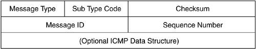
The type and the code of an ICMP message are contained in the ICMP header, shown in Figure 1.3. Figure 1.3. The ICMP header.
|
EAN: 2147483647
Pages: 163