3.3 Swapping and Advanced SwappingLoading Methods
3.3 Swapping and Advanced Swapping/Loading MethodsOne of ADSL's most important and essential features is the bit-swapping described in [1]. Bit swapping accomplishes several features either crucial or desirable for DSL operation by:
The first two features are essential to proper operation of the DSL modem. DMT modems use minimal equalization, which is why they require far less digital signal processing operations for high-performance operation than wideband ("single carrier" or "baseband") modulation methods that alternatively require long equalizers (DFEs, see [1] or Chapter 2) for best operation. The price paid for such low-cost high performance is the need for continuous handshaking on a control channel between the receiver and transmitter that continuously optimizes the allocation of information, and possibly also energy, to the different subchannels in a DMT modem. This handshaking not only implements the function of the adaptive equalizer in wideband modems, but it also continuously ensures that the optimum transmission band is maintained, or equivalently that the best possible reliability is maintained . Such continuous optimization occurs through the bit-swapping control channel (also known as the AOC ”see Section 3.3.1). The swapping channel is highly robust as discussed in Section 3.3.1, but may be undesirably slow to react in some situations, so Section 3.3.2 discusses accelerated swapping protocols (sometimes known as "express swapping" that are allowed in advanced ADSL and DMT-based VDSL modems). Sections 3.3.3 and 3.3.4 discuss some advanced uses of swapping that have come to be more common as ADSL systems are increasingly improved by manufacturers. Section 3.3.5 discusses advanced loading algorithms that can be used for swapping or loading, basically due to H. Levin [10] “[13] (this area was not covered in [1]). In particular the often- encountered question of "how to load" with various types of coding and associated redundancy present is discussed in Section 3.3.5. 3.3.1 Explanation of SwappingFigure 3.12 illustrates the basic concept of bit swapping. There is a DMT controller in both transmitting and receiving DMT modems. This controller sets the number of bits and transmit power level of each subchannel. A protocol exists on the AOC [9] between the two modems. There are essentially three types of commands on the AOC: swap request, swap acknowledge , and extended swap request. Swapping commands are identified on the overall control channel by a leading byte of all ones. A swap request from the receiver to the transmitter on the AOC has an additional 8 bytes of information, that is, four 2-byte fields that specify a tone idex (0 to 255) in the first byte and an action (increase or decrease the number of bits allocated to that tone by 1, or increase or decrease the power of that tone by 1, 2, or 3 dB, or do nothing to that tone) in the second byte. Usually the same tone index is transmitted twice with first an increase/decrease in number of bits, and subsequently a corresponding energy adjustment. However, it is possible to increment a single tone four times with no energy change and many other combinations as well. A swap acknowledgment from the transmitter to the receiver on the AOC is an extra 2 bytes that repeats the all ones pattern in the first of these two additional bytes, and then specifies a superframe number (from 0 to 256) on which the swap will be implemented by the transmitter. Superframes start with count number equal to 0 on the very first transmission of customer data, and subsequently, increment modulo 256 every 68 DMT symbols (or 69, counting any synch symbol). Loading algorithms for incrementing and decrementing bits and energy are discussed in Section 3.3.5, most specifically Campello de Sousa's method in [14] ”now also known as having been proposed earlier by Levin of Motorola [10]. An extended swap has 12 additional bytes, allowing up to 6 tones to be specified for alterations of bits and/or energy. Typically, extended swap is used to swap from 2 bits to 0 or vice versa on a subchannel by sending an increment/decrement command twice, along with a corresponding energy adjustment for each of donor and recipient tones.
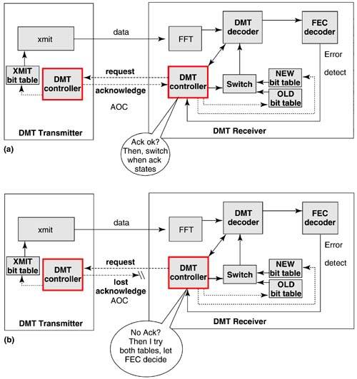
Figure 3.12. Illustration of functional and dysfunctional AOC. (a) Bit swap with AOC functioning properly. Receiver DMT controller switches to new bit table at time specified by AOC acknowledgment. (b) Bit swap with lost AOC acknowledgment. Receiver DMT controller tries both switch settings using the FEC decoder correct/errors detect to arbitrate. The bit swap protocol is resilient to loss of handshake commands, both bit swap requests and/or bit swap acknowledges. Although loss of commands is extremely rare because of an error-corrected-plus-three-of-five command protocol, it is conceivable that a gross channel disturbance might cause a command to be missed: A situation sometimes suggested as a "flaw" in bit swap suggests that such a miss causes modem disfunction. Actually, this statement is incorrect, and there are many correct implementations that easily and simply recover without error from a command loss. The following section offers the conceptual implementation of Figure 3.12 as one of many that suffice. In the implementation of Figure 3.12, the receiver typically initiates a swap of a bit from one tone to another tone through the AOC DMT-control channel shown (this channel is actually embedded in the data channel, but shown separately for illustration in Figure 3.12). A bit swap "request" command is sent from the receiver to the transmitter through a heavily protected reverse "AOC" channel. [10] The transmitting modem then "acknowledges" the request through the forward "AOC" channel and specifies a time for the new bit table to be implemented. If either command is not received for any reason, the receiver can simply monitor the incoming signal using two bit tables (this can be implemented simply in several fashions ), OLD and NEW. The FEC corrected/ detected error flag (syndrome) can be monitored for which of the tables, OLD or NEW, is correct. The receiver then knows whether the swap was implemented by the transmitter or not, even if one or both of the AOC commands could not properly traverse the channel. Good bit swap implementations can thus be fully resistant to AOC channel errors. This also means that the channel itself need not be burdened with excessive use of commands for double acknowledgments, and so on, which leads to an increase in overhead bandwidth. Another method for detection of an implemented bit swap is to monitor the tone to which a bit is added. This extra bit leads to a larger constellation, with the probability of a new outer point corresponding to the extra bit, tending toward one in just a very short time. This method, while extending the error burst by 1 percent or so, is extremely simple to implement, corresponding to a complexity increase of less than 0.1 percent in the receiver signal processing.
Bit swap is an essential feature of a DMT DSL modem. A simple situation is illustrated in Figures 3.13 and 3.14 for a 4.25 km 26-gauge twisted pair. One bit distribution corresponds to the DSL being the first one deployed/used in a cable. The second distribution corresponds to the new bit distribution that is best when one crosstalking DSL appears. This crosstalker is an HDSL, but one could readily produce similar results for other types of crosstalkers and/or noises. The 1.5 Mbps data rate is readily achieved with the HDSL crosstalker both when the bit distribution is properly optimized for 0 crosstalkers (34 dB margin) or for 1 crosstalker (19.3 dB margin). These margins do not include FEC coding gain. Figure 3.13. Optimized bit distributions for 0 crosstalkers and 1 crosstalker on 4.25 km 26-gauge twisted pair (xtalk is HDSL, background noise is “140 dBm/Hz). Figure 3.14. Margin for NO SWAPPING when the crosstalker is turned on. However, if the original crosstalk-free bit distribution were to be maintained after the single HDSL crosstalker turned on, then the margin is negative 6dB (-6 dB) on some of the tones. These tones will make errors with a probability of about 1/10, leading to a few tones in error on each symbol. Forward error correction can correct these errors temporarily, but there will no longer be any immunity to impulse noise nor to further changes in the channel noise like additional crosstalkers. Any further slight disturbance results in unnecessary retraining of the modem and loss of service when bit swapping is not used. The performance loss is over 25 dB if bit swap is not used (19.3 dB “ (-6 dB) = 25.3 dB). Bit swapping by contrast allows the first modem to vary its bit distribution to the new optimum bit distribution, allowing a full 19.3 dB of margin to be achieved. The swapping also protects the HDSL system as the ADSL actually creates less crosstalk for HDSL after swapping to the new bit distribution. Optimum bit swapping methods for discrete distributions (see [1]) will actually correct the worst tone (the one with lowest margin after the crosstalker ignites) first, then each successively better tone until the margin is restored. The very first few swaps will eliminate the most negative margins and begin to restore the link's ability to deal with additional noises. Eventually, depending on the speed of swapping (usually 20 “100 swaps per second is a good number), the optimum 19.3 dB will be restored, although standards only mandate an ability to implement 1.25 swaps/second. However, a vendor's modem can request swaps more frequently and if they are implemented by the other modem, profit from the increased speed of swapping. For 20 “100 swaps/second, the new bit distribution in our example would be implemented in a couple of seconds without any bit errors or loss of service or additional errors (beyond those that occur for other reasons). This bit swapping process is seamless without errors, and without service interruption or need for retraining. There are many other types of crosstalk and other noise examples that lead to bit swapped correction of the DMT distribution. This simple and realistic example shows one case in which bit swap is necessary for restoration of margin and continued flawless operation of the DMT modem. There are many other similar cases that could be produced. Retraining or fast retraining need only be used for gross channel changes that essentially would otherwise have permanently disabled the modem. 3.3.2 Express Swapping MethodsA concern in ADSL modems is the time that it takes for swapping to implement a request. Data could be lost during this time if a large change occurred and the FEC were temporarily overwhelmed during the time that the swaps are correcting the situation. The solution to this is known as "express swapping," which allows an entire bit table, or equivalently any number of tones/subchannels, to be simultaneously specified in one command. This command is standardized for DMT VDSL, which has as a subordinate mode of operation an advanced ADSL modem [15]. The designer needs to be careful in the use of express swapping commands in that crosstalk into other channels can be dramatically altered in a short period of time, so while the present channel is corrected, the modem should not violate spectrum constraints into other modems. One can show that in all but pathological situations, a series of express swaps (often called distributed iterative water-filling ; see Chapter 10) does actually converge to a stable energy distribution for all the lines involved. Fortunately, swapping tends to move energy away from crosstalkers rather than into the common spectra and thus is a stable process even when implemented swiftly in an uncoordinated fashion on multiple lines in the same binder. The express swapping AOC command can dramatically increase the speed of swapping (by a factor of more than 100). Express swapping adds one additional AOC command and an associated express swap time-out mechanism. The command format is:
An express swap command is sent only one time and has an internal 2 byte CRC protection for error detection. The first byte is a marker for the express command format, and the last two bytes are the CRC for error detection in the command receipt by the transmitter. The express bit-swap request message has the following format:
The express swap (ES) control byte has its most significant bit set to 0 if the transmitter should implement the ES on the next superframe. This bit is set to 1 if the transmitter should implement the ES on the next-to- next superframe. The remaining 7 bits enumerate the number of tones, n , that are changed by the next 2n bytes in the command. Each tone has two bytes ”the first indicates which tone should be changed and the second byte quantifies the change. In the second byte for each tone, the new absolute number of bits is a number between 0 and 15 and is encoded in the upper nibble (4 bits) according to 0000 for no bits, 0010 for two bits, ..., 1111 for 15 bits. [11] The relative gain is a 2's complement 4-bit quantity between “4 and +3.5 dB (with .5 dB increments ) with most significant (sign) bit. 0 bits implies 0 energy.
There is no ES acknowledge command. The receiver that initiates an ES shall be responsible for monitoring the returned DMT signal to determine if the command has been implemented by the transmitter. If the swap has not been detected on the correct superframe, the receiver shall assume the transmitter did not implement the command. The ES initiating DMT receiver may then elect to again initiate a second ES command, another AOC command, or a retrain. This command is not sent five times, but instead sent only once to improve speed. The CRC at the end of the command follows the same byte CRC protocol as used in initialization for confirmation of correct receipt of message fields. The polynomial used is g ( Z ) = Z 16 + Z 12 + Z 5 + 1 , where Z is an advance of one bit period ”equivalently numbering the bits starting with the first bit of the message header as through m 16 n +32 and forming m ( Z ) = m Z 16 n +32 + m 1 Z 16 n + 31 + ... + m 16 n +32 ,the check bits are. c ( Z ) = m ( Z ) modulo g ( Z ). The maximum number of bytes in a command (which likely is rare in occurrence) would be 260. A transmitter unable to accommodate this length of command would simply ignore it, thus forcing the receiver to perhaps attempt different corrective mechanisms, which could include breaking this large-length command into smaller commands. Dynamic Rate AdaptionES also provides a mechanism by which data rate could be adapted if allowed without disruption of data flow across link, which is also possible in present versions of bit-swap commands. However, use of such a facility requires higher-level control of the DSL link to allow such rate change. Thus, express swap does not change this particular aspect of ADSL operation, it just provides a faster mechanism for executing it if desirable. Otherwise, the receiver should ask for bit distribution changes that maintain the same data rate. 3.3.3 Intentional Tone Zeroing and Q-ModeTones may be zeroed in a DMT modem, which amounts to setting the corresponding entry in the bit table to 0 bits, which implies also that zero energy should be sent. Such zeroing has come into use for many reasons:
Additionally, G.992.3 and G.992.4 ADSL modems have considered the use of a Q-mode of operation when idle or useless data occupy the line. The basic idea is to transmit known idle symbols that have reduced PAR ratios during this time period. If the PAR is reduced (by perhaps as much as 10 dB for some known and/or repeated DMT line signal transmitted during Q-mode), then the current delivered to the line driver can be reduced, saving power on each DSL line. In the DSLAM, this can save 1 “2 watts/line (of a figure that today without statistical multiplexing factors is about three watts/line). In the upstream direction, this may be a smaller savings for a DSL modem in a battery- powered lap top, but total power consumption of the CPE modem can be then a few hundred milliwatts. The area is best summarized at time of writing by Carlson in [16], and no proposal had been agreed for standardization. Basic Q-mode proposals share the following constraints:
Areas of dispute seem to be how to communicate the "idle" condition from higher levels of protocol to the modem physical layer and whether to use very low PAR signals (basically a " chirp " DMT signal has the lowest PAR ”see [17] ”of 3 dB and various proposals try to approximate this) but also perhaps desire to maintain the signal constellation points used during normal transmission to simplify implementation. Statistical multiplexing and dynamic spectra management may be able to exploit the type of Q-mode signal used (see Chapter 10). The work in ITU Q4/15 has suggested that Q-mode (using reduced PAR transmission) would provide little benefit for transmitters using newer types of line drivers. Q-mode was not included in G.992.3/4, instead L2-mode was provided that is a reduced power mode used for periods while no payload data is being sent. Signal energy is maintained on the line during L2-mode to minimize changes in crosstalk energy to other lines (non-stationary behavior), and to enable rapid resumption of normal transmission. 3.3.4 Time-Varying CrosstalkUsually with always-on DSL systems, crosstalk is relatively stationary in spectra (it may appear slightly time variant simply because of clock differences between DSL systems). A single excitation of another DSL in the binder to an always-on state can usually be accommodated by the swapping mechanisms described earlier. However, some crosstalkers periodically vary with time intentionally. Still others make gross adjustments in their spectra using nonstandard methods. These may create a problem for some DSLs, depending on the time-variation pattern of the non-stationary crosstalk. The greatest single offender in terms of time-varying crosstalk are nonstandard ping-pong DSL systems that have been installed by some competitive local exchange carriers in unbundled DSL COs. [12] Such systems, while proprietary, can switch upstream and downstream transmission at a rate of, for instance, 8000 times per second, or every 125 ms. However, any "ping-pong" rate is possible, and some systems dynamically vary the duty-cycle as a result of the payload data rate. The DMT receiver thus needs to know if crosstalk is time-varying. A classic error in the DMT receiver would be to measure noise on each tone as an average over time without regard to whether individual noise samples over a reasonable period of time were exhibiting statistically aberrant variation. For instance, with a ping-pong modem crosstalker one might expect to see roughly periodic variation in the noise variance. An ADSL modem with such advanced noise monitoring can bit load for the worst-case noise expected rather than the average, thus improving reliability (at the expense of data rate or range). Such a modem can also code differently or even try to vary the bit distribution with time to counter the crosstalk variation with time-varying bit distributions.
Annex C of the worldwide ITU G.992.1 and G.992.2 standards [3] is another example of a system designed for time-varying crosstalk in Japan. ISDN transmission in Japan is "ping-pong" or TDMA with a periodic variation of 400 Hz. Such a system introduces time-varying crosstalk into ADSL at least over the common ADSL band. Thus the ADSL system needs to correspondingly adjust bit tables according to a 345-DMT-symbol "hyperframe" that aligns with five successive 17 ms-long DMT-ADSL superframes (of 68 data and 1 synch symbol per superframe). This hyperframe is 85 ms long and corresponds also to exactly thirty-four "ping-pong" cycles of the Japanese ISDN signal. There are consequently 2 bit tables in each direction, one for each direction of transmission of the ISDN crosstalker. Swapping occurs automatically at regular intervals between the two tables ”their use is standardized with respect to a 400 Hz network clock supplied to the modems in Japan. Additional bit-swapping is implemented within each of the tables with a slightly modified bit swap command that allows specification of which table the command applies as in Annex C of [3]. This is sometimes called dual-bit loading. Such noise would disable conventional PAM transmission, so SHDSL methods are dual-bit loaded symmetric DMT systems that use 1.104 MHz (256 tones) in both directions. 3.3.5 Loading with CodesReference [1] reports on several loading algorithms, including the basic greedy concepts suggested by Hughes-Hartog and developed by Campello. Levin and colleagues [10] “[13] have extensively studied this area and deserve perhaps equal or greater credit for the methods previously known as Campello algorithms, and henceforth now called "Levin-Campello" or just LC. Energy Functions and Table Although reference [1] simplified the explanation of loading algorithms using the "gap" approximation , both Levin and Campello independently noted that the gap is not exactly constant and that with integer numbers of bits per tone as a restriction, this constant-gap presumption can unduly reduce performance (in a worst-case situation by a dB of margin). The solution is to construct a table of next energies to transmit the next bit (for 0 bits to 15 bits) for each and every tone. This incremental energy table essentially scales with the inverse of the subchannel SNR Figure 3.15. Bit-swapping table illustration. Light arrows indicate position to which energy for adding a bit to constellation on current tone is listed; heavy arrows indicate the positions of least cost and most saved energy over all tones. A certain number of bits, including any parity or overhead bits, needs to be transmitted. The LC algorithm simply allocates each successive bit (up to the total) to the place of least incremental energy. Swapping is executed in the algorithm whenever the amount of energy to be saved on tone n last exceeds the amount of energy to be added on tone n next by a threshold amount. The threshold is set sufficiently high to prevent continuous swapping unnecessarily and may be on the order of 1 dB (a 1 dB savings on one tone does not correspond to a 1 dB overall savings, and indeed is far less overall with many tones used in DMT). In older ADSL standards, 1-bit constellations were not allowed, but that restriction has now been removed so that swapping is simplified and the algorithm here applies directly. When swapping must occur with a 2-bit minimum, Levin has created and patented a series of exception procedures that address most of the contingencies in [11]. Two-dimensional trellis coding (which is not used in ADSL) or two-dimensional turbo or LDPC codes (which may be used in future ADSL) require only a simple modification of the energy table if parity and puncturing are well defined. Four-Dimensional Trellis Coding Redundant BitsWhen four-dimensional trellis coding is used with a system such as in Figure 3.15, the number of extra or redundant bits varies with the number of tones. Basically, there is one redundant bit for every two tones. When the number of tones is odd, one of the tones is paired with a tone carrying zero bits to create the appearance of an even number of tones. The total number of bits, including the trellis-code extra redundancy bits, is loaded on the tones as if the system were not coded. For encoding and decoding purposes, each successive pair of tones is presumed then to have exactly one redundant trellis coding bit with respect to the input of the encoder and the output of the decoder for that pair of tones. When bits are moved into previously unused tones by the LC algorithm, or all bits have been removed from previously used tones by the LC algorithm, the number of used tones can vary. Thus, the number of redundant bits can vary. Levin's modification of the LC procedure in this case is to retain a counter for N * the number of "used" tones (i.e., the number of tones carrying 1 “15 bits of information). When N * is even and increases to the next higher odd number, the LC algorithm adds one extra bit at tone n next . When N * is odd and decreases to the next lower even number, the LC algorithm deletes one extra bit at tone n last . Thus, AOC swapping commands may carry two added bits and one deleted bit, or possibly one added bit and two deleted bits when trellis coding is used, but the actual data rate remains constant. Gain-Swapping or Gain AdjustmentVariation of gain on a tone in ADSL is allowed up to an increase of 2.5 dB and any level of decrease (with zero gain meaning the tone is not used). Gain swapping can be used to move energy from one tone that may have an optimal solution to exceed a power spectral density mask to another that would not, or just to improve performance slightly. The gains are multiplicative factors that are applied to each tone in the ADSL DMT transmitter, and thus essentially can be viewed as part of the channel and absorbed into the table for the LC algorithm. Essentially, when the transmitted energy on a tone will exceed the maximum allowed by a PSD, that tone has extra energy. That energy can be reallocated to a tone that would not exceed the mask. The table for LC is appropriately scaled so that n next will be forced to occur on tones that have will not exceed the maximum power spectral density. Generally PSD masks in ADSL are not a good idea even though imposed by most transmission standards, including ADSL. They are imposed under the assumption that limiting the mask level will limit crosstalk. However, they may limit total power transmitted on a long loop at low frequencies below the 20 dBm limit, which reduces range substantially. A higher PSD at such lower frequencies will not cause damage to other services statistically because the crosstalk coupling is relatively low and ADSL modems will actually bit swap away from one another automatically to a globally better use of spectra between the modems. Although this still works with the PSD limit, it works better without it. Additionally, actual crosstalk coupling functions are highly variable so the likelihood of a problem occurring as opposed to just letting the modems find a better mutual optimum is actually favorable to the modems by a large margin. Imposition of spectrum masks (like “40 dBm/Hz in ADSL) in standards does allow for some level of variation, like 3 dB, which helps a bit. Nonetheless, engineers have for the longest time argued about and felt the need to impose spectral masks as perhaps a learned legacy of questionable need and habit than of technical necessity. More advanced systems such as those in Chapter 10 will further mitigate the need for spectral masks. A classic use of gain adjustment is the situation where the channel SNR characteristic is fairly smooth when ordered. As the LC algorithm progresses, there is usually a jump in transmitted energy from the last tone, using bits to the first tone allocated b n + 1 bits. This produces a saw tooth character to the transmitted energy characteristic. Because the transmitter accepts during initialization a recommendation from the receiver to adjust its transmit energy levels according to the gain factors g n , these factors may need to be adjusted when swaps occur so that the correct amount of transmit energy is maintained on each subchannel. For instance, if the LC algorithm suggests that a bit be moved from n last to, n next then there is a corresponding transmit energy adjustment on each tone, which is and and thus the gain adjustments are then and For more details on loading and swapping, see [21]. Forward Error Correction Redundancy PercentageEarly work [18] on forward-error correction overhead with RS codes for ADSL suggested a rough 4 percent for 5 “8 Mbps transmission, 6 percent for 2.5 “5 Mbps, and 8 percent for less than 2.5 Mbps. These simulations were conducted for a few lines. FEC percentages are restricted to use even numbers of parity bytes and so these numbers can only be approximated in practice. Furthermore, the exact best level of FEC to use on any line depends on the line, the noise, any impulse noise, and finally the delay requirement. Thus, many have noted that the above rule of thumb can reduce performance in situations different from what were initially derived. Ideally, the designer knows in advance exactly how many parity bytes (see [1]) will be added in the RS code in ADSL beforehand, perhaps based on impulse-noise/delay constraints. The total number of bits, data plus parity for RS, are then loaded (with or without trellis coding according to the LC above) to the tones. The energy tables for incremental addition of a bit on any tone could be reduced by the presumed gain of the code. This presumed gain of the code would take into account the redundancy. However, the problem is that the amount of coding gain is not constant because greater redundancy increases the gain at the expense of data rate, so there is a trade-off. Thus, as Levin notes [13], it is possible to compute a "gross coding gain" for any FEC system, which is simply the amount of coding gain (as determined by graphing probability of error with and without coding at the same clock rate) without regard to the data rate loss. This number is relatively fixed for any given block length and number of parity bits at probability of error 10 -7 , which is the standardized design point in ADSL. Levin provides the following useful table of such coding gain:
Each entry in the other table of incremental energies used in the LC algorithm can be scaled down by the amount in this table corresponding to the code parameters (block length 20, 40, ..., 255) and parity (2, 4, ..., 16). The LC algorithm is then performed for each possible combination of block and parity, and the system with the highest margin (or highest data rate for rate adaptive) over the RS code-parameter choices can be maintained. Interleave depth for impulse noise protection may then be determined. If impulsive noise is present, other factors may enter the choice of code parameters outside of the loading algorithm described here. The gain can be 1 dB with respect to using the above rule of thumb. | ||||||||||||||||||||||||||||||||||||||||||||||||||||||||||||||||||||||||||||||||||||||||||||||
| Top |
EAN: 2147483647
Pages: 154