Technology Overview
| Let us try to answer some of the questions listed in the previous section. But, before we answer them, let's briefly compare IPv6 header and IPv4 header information, as shown in Figure 11-1, to note the differences. Figure 11-1. IPv6 and IPv4 Packet Header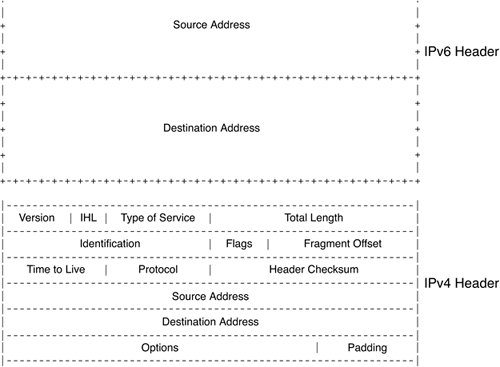 The IPv4 header is 4 bytes or 32 bits. In the world of classless interdomain routing (CIDR), net masks define the network portion of the address rather than the host portion of the address. IPv6 has 16 bytes or 128 bits of address space. The header is slightly different from IPv4 as shown in Figure 11-1. The flow label is a 24-bit field. It can be used for QoS and is much larger than 6-bit DSCP field in IPv4. The hop limit information is nothing but the TTL field of IPv4. To ease migration and coexist with IPv4, there are capabilities to tunnel or translate IPv6 addresses to IPv4 addresses. Tunneling allows the transporting of IPv6 frames from the ingress of the IPv4 network to the egress without acting on the IPv6 header information. IPv6 PEAs mentioned earlier, tunneling of IPv6 packets can be done using IPv4; then the IPv4 frames can be transported across the MPLS network. Another form of tunneling is using the label as an encapsulation instead of another IPv4 header. This method of transporting IPv6 packets across the MPLS network by using the label as a mux/demux field, and the tunneling encapsulation is called IPv6 PE (6PE). Refer to Figure 11-2. Figure 11-2. IPv6 Provider Edge (6PE)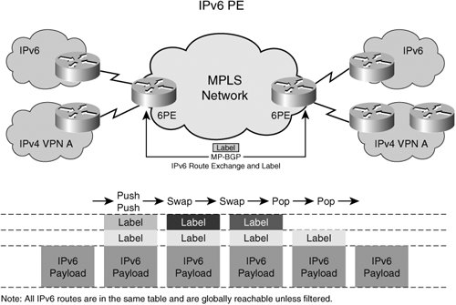 In the 6PE environment, each provider edge router is a dual network stack device with IPv6 and IPv4 stacks. The edge router peers with the customer routers with IPv6 and IPv4 separately. Both IPv4 and IPv6 addresses are exchanged between the edge router and customer routers using a routing protocol. The customer edge devices do regular PE-CE routing via either the dynamic routing protocols or static routing. The PEs peer with each other directly or by using route reflectors for the exchange of IPv6 routes in addition to IPv4 routes. The core routers learn only IPv4 addresses that are advertised in the IGP. The core routers in the network do not have any IPv6 visibility and cannot reach IPv6 addresses. The labeled IPv6 packets are forwarded on the IGP-based, label-switched paths (IGP LSP). Multiprotocol BGP ExtensionsTo distribute IPv6 address information between PEs, Border Gateway Protocol (BGP) is extended to carry IPv6 addresses. The address family identifier is used to distribute the IPv6 prefixes within BGP. A label associated with that IPv6 network prefix is also advertised as part of BGP extended communities, similar to the IPv4 VPN extensions. The PEs then exchange this IPv6 prefix and label information via the iBGP session between them, as is done with the L3VPN. Just as the PEs advertise the IPv4 reachability, they also advertise IPv6 reachability with the ability to resolve the IPv6 routes to an IPv4 next hop. (Refer to the Figure 11-2 for details.) Packet PathAs we stated earlier, the PEs are dual-stack devices that support IPv6 and IPv4 on the same port or on different ports. When IPv6 packets come from the CEs, the PE looks up the v6 forwarding table and finds the IPv4 BGP next hop. It then imposes the IPv6 label assigned to the IPv6 prefix by the egress PE. The PE then imposes the IGP or tunnel label to get to the egress PE (IPv4 BGP next hop) via the PSN tunnel or a label-switched path. The result is the same dual-label stack that we see in VPNv4 (L3VPN) cases. The packet is switched through the network core using the top label, and when the packet arrives at the egress PE, the egress PE looks up the label and forwards the IPv6 packet to the destination interface corresponding to that prefix. This looks exactly like the IPv4 VPN case, but the difference here is that all IPv6 addresses are in one address space. The packet handling for 6PE is no different from the VPNv4 case, except that all v6 CEs/addresses are in one domain and can be reached via IPv6 unless route filtering is applied. The network core does not understand any IPv6 frames and is running standard IPv4 with IGP routing protocols, such as OSPF and IS-IS. The P routers have no knowledge of the IPv6 label and are only label-switching packets based on the top label or PSN tunnel label. All routing polices that are applicable also apply in this case. IPv6 VPNs (6VPE)Much like the IPv4 VPNs, service providers might also want to keep the traffic of one VPN separated from the traffic of another in the IPv6 space. To deliver this traffic separation between IPv6 devices, service providers have two choices. One choice is to perform route tagging of IPv6 routes via the BGP communities and then filter the IPv6 routes based on those tags. Route TaggingRoute tagging is a technique that allows the PE to assign a tag (community of interest) to any route as part of a BGP attribute. The tag is called a community. By assigning route tags, upon import of routes, a PE can then filter the routes to exclude those that do not belong to its community of interest. This prevents routes from being populated in the PEs where these routes are not needed; it also prevents network reachability. This model is simple to understandall IPv6 traffic belonging to one VPN is tagged with the VPN name. When PEs receive the routes, they filter these routes based on policies. By tagging routes and selectively importing/filtering the routes, extranets can also be built. But as networks get larger and more complicated, efficient filtering techniques are needed to scale this model upwards to address many VPNs and many routes within the VPN. Virtual Routing and Forwading with IPv6Another model for IPv6 VPNs is to use the similar virtual routing and forwarding (VRF) structures, as we used in the IPv4 L3VPNs, and separate the IPv6 routes on a per-VRF basis. This separation of routes is similar to that of the IPv4 model. CEs are connected to the PEs and are placed in a VRF. The PEs have a separate routing and forwarding table per VRF/VPN, and IPv6 routes from the CE are populated in these VRFs. The peering model is similar to VPNv4, in which PEs exchange IPv6 routes in iBGP using the IPv6 address family extension to the MP-BGP. Labels are then distributed in the same way as the IPv4 prefixes are. All the functionality to separate one v6 address from another using route distinguishers and route targets apply here in the same manner. Route targets can be imported or exported in the same manner as IPv4 routes to create intranets and extranets. Packet PathWhen IPv6 packets come in to the PE from the CE of a VPN, the PE looks up the v6 route in the VRF and finds the egress IPv4 BGP next hop and VPN label associated with that IPv6 prefix. It imposes the VPN label and then forwards it onto the PSN tunnel or onto a label-switched path toward the egress PE, as shown in Figure 11-3. Figure 11-3. IPv6 VPNs (6VPE)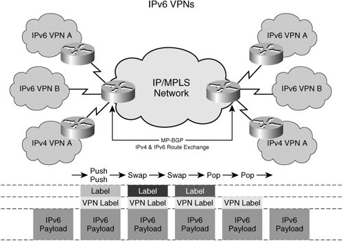 The label-switched path between the ingress and the egress PE is set up independently of the VPN route exchange. The network core can be IPv4, and only the PEs are IPv6-capable. This allows layering of IPv6 VPNs services and a rapid start of IPv6 deployments. Alternatively, the network core can also be a complete IPv6 network, in which case the label distribution protocols, such as LDP and RSVP, must be IPv6 capable. By using 6VPE, the same L3VPN available in IPv4 can also be provided with the same QoS characteristics and flexibility. This means the administration model for IPv6 is no different from the IPv4 model, and the IPv6 model has potentially more flexibility and a much larger address space. Due to the much larger address space of the IPv6 model, users probably will not use NAT for IPv6 addresses anytime soon. However, tunneling and translation from v4 to v6 and vice versa is certainly necessary. For example, a v6 device, such as a mobile phone, needs access to the v4 Internet for web browsing or other applications. The IPv6 request can go either to a central gateway in the provider network or within the customer network and be translated there into an IPv4 space and sent across the IPv4 network. The Coexistence of IPv4 L3VPN and IPv6 L3VPNIPv4 L3VPNs can coexist with IPv6 L3VPNs on the same PE and in the same VRF table. A single VRF table can be used to store IPv6 and IPv4 addresses belonging to the VPN. The CEs advertise IPv4 and IPv6 addresses, while the PE independently advertises IPv4 and IPv6 addresses with route targets. Allowing the coexistence of IPv4 and IPv6 L3VPNs provides a smooth migration of networks from IPv4 to IPv6. It also enables the seamless coexistence of services regardless of the IP protocol version. Service providers can continue to operate their IPv4 services while introducing new IPv6-based services on their networks. Without MPLS, the network operators have to tunnel IPv6 through the IPv4 network or upgrade the entire IPv4 network to IPv6 or to dual stack. This can be difficult to manage and operate. Using MPLS, IPv6 can be easily layered in the network while keeping the operational paradigm the same as that of IPv4. Mobile wireless integration and residential broadband integration are now possible with a virtually unlimited address space because of IPv6. IPv6 Network CoreTo recap 6PE and 6VPE operations, we know that for 6VPE and 6PE, each IPv6 prefix is resolved to an IPv4 BGP next hop. The setup of LSP to the BGP next hop is done using LDP or RSVP for IPv4 FECs. The traffic mapping to LDP LSPs or TE tunnels is based on IPv4 addresses, and IPv6 is transparent to the TE tunnel setup or forwarding of traffic. At some point, we hope all networks will become IPv6. To get to that point, all routing protocols and label-distribution protocols need to be IPv6-capable. IGP protocols with IPv6 are already available from Cisco. In the future, LDP and RSVP with native IPv6 support will also be available. Protocol details can be found in RFC3036. With native IPv6 support for LDP or RSVP-TE transport, LSPs will be signaled for IPv6 addresses directly without the layering that is needed for 6PE or 6VPE. For traffic engineering to be enabled in an IPv6 core, all traffic engineering features (such as autoroute and static route) must work with IPv6 prefix mapping. The forwarding of IPv6 traffic must be done onto TE tunnels, and the tunnels themselves must be signaled using RSVP with IPv6 extensions. The techniques used with fast reroute can also be used to protect IPv6 traffic from link or node failures. In short, the native IPv6 operation is no different from the IPv4 operation for MPLS because the label space, size, signaling, and forwarding do not change with IP protocol version. Inter-AS Networks for 6PE and v6VPNsInter-AS capability is also important because provider networks are seldom single autonomous system (AS) networks. IPv6 information must be carried across ASes between PEs. The peering model at the Autonomous Systems Boundary Routers (ASBR) is no different from IPv4 peering, but both ASBRs must be configured with IPv4 and IPv6 address families. The three interconnect models discussed in RFC 4364 apply to both IPv4 and IPv6. These interconnect models are briefly described here:
IPv6 QoSQoS is an integral element of the IPv4 service offering; therefore, for any transitional capability to IPv6, all IPv4 services and more must be offered in the IPv6 network. IPv6 has a traffic class field that is 8 bits. This field provides the priority of the IPv6 frame and can easily be mapped from the IPv4 DSCP byte. This traffic class field is designed to use the differentiated services definition; hence, in the MPLS network, it carries the same significance as the IP DSCP field. All the details discussed in Chapter 9, "Quality of Service," regarding marking classification, policing, scheduling, and WRED also apply to the IPv6 frames. Additionally, a 24-bit field exists in the IPv6 header and is called the flow label. This label is used as a flow designator by the source for special handling of packet sequences, such as nondefault class of service or real-time service. Although this flow designator provides many more options in terms of QoS, it is still under discussion, and the RFC does not clearly define the usage of this flow label. Thus, there is no standard way of dealing with the flow label. Currently, Cisco products do not use the flow label field. MPLS QoS for IPv6Because MPLS label information does not fundamentally change for IPv6, the MPLS QoS model for IPv6 does not change from IPv4. The same EXP markings are used to classify traffic from high priority to low priority, and standard QoS techniques are used to deliver MPLS DiffServ for IPv6 packets. In addition, the mapping of the traffic class field is done much in the same way as the mapping of the DSCP field. Refer to Chapter 9 for more details on the DSCP mapping to EXP bits. Should more QoS classes be required, the L-LSP model discussed in Chapter 9 can also be used for IPv6 traffic. Additional mapping of flow labels to MPLS QoS is not defined at this stage. |
EAN: 2147483647
Pages: 162