3.4 Partitioning Case Study--Layer 2 Switch
|
|
3.4 Partitioning Case Study—Layer 2 Switch
Consider a Layer 2 Ethernet switch, which switches Ethernet frames between ports. This example system consists of 8 Ethernet ports for switching traffic and a management Ethernet port. It contains a CPU which runs the software for the system. For now, assume that there is no hardware acceleration and that all the switching is done by software running on the CPU.
Figure 3.3 shows the software architecture of the device. It requires the following:
-
Driver(s) to transmit and receive Ethernet frames from the ports
-
A set of modules/tasks to run the protocols required for the switch
-
A set of modules/tasks required for the system operation and management
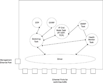
Figure 3.3: Typical Architecture of a Layer 2 Switch.
3.4.1 Device Driver
The device driver is the module closest to the hardware and is responsible for transmission and reception of frames. For transmission, the driver obtains the data from its higher layer, while, for reception, the driver needs to pass the received frame to its higher layer. The driver typically handles frames received from the hardware controller by either polling or by interrupts generated when a frame is received. The method used depends on application requirements.
With polling, the driver polls the device for received frames at periodic intervals. If the device indicates that frames have been received, the driver reads these frames from the device, frees buffers for the device to read frames into, and passes the frames to the higher layer. With interrupts, the driver receives an indication that a frame has been received, based on which it can read the frames from the device.
Polling is a relatively inefficient way to handle frames, especially if frames arrive infrequently. The driver polls the device even when no frames have been received, expending processing time which could be spent in other operations. Interrupts are more efficient but can easily swamp the system when frames arrive at a rapid rate. In the Layer 2 switch, frames can arrive at a maximum rate of 14,880 64 byte frames/second on a 10 Mbps Ethernet. If an interrupt is generated for each of the frames, it can easily overload the system. To handle this, drivers use a combination of interrupts and polling in conjunction with the controller, as described below.
Several techniques are used to optimize controllers for receiving frames. Consider a case in which a list of multicast Ethernet addresses are to be recognized. In the Layer 2 switch, one such multicast address is used for Spanning Tree Protocol (STP) frames. STP is used to ensure that loops are detected and eliminated in the bridge topology. It involves periodic transmission of frames between bridges.
The STP frames use the multicast MAC address 01-80-C2-00-00-00, so the Ethernet controller needs to receive and pass up all MAC frames with this multicast address in the destination address field, whenever STP is enabled. The controller can perform this match on chip registers which store the MAC addresses. The driver programs this register with the MAC addresses based on the higher layer configuration. The higher layer configuration can take place via a Command Line Interface (CLI) with a command like “Enable STP”, which, in turn, causes the “enable” event to be propagated all the way to the driver to receive STP multicast frames, Thus, higher layers need not be aware of the details at the driver level.
Frame Reception
In Figure 3.4, a driver provides receive buffers to the controller. These buffers are located in system memory, and the controller can access these receive buffers to directly DMA the received Ethernet frames. Typically, the controller manages the buffers in such a way that, if the full frame does not fit into the first buffer, it reads a portion of the frame into the first and copies the remaining into the second buffer, and so on. The amount of “overflow” into the next buffer will be determined by the size of the frame and the size of the buffer.
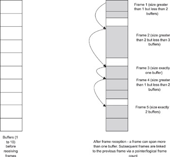
Figure 3.4: Frame Reception and Buffer Handling
In Figurer 3.4, five frames of different sizes are received into the buffers. The figure shows that a frame “points” to the buffer housing the start of the next frame. This can be done using a pointer or an end-of-frame indication. Using Figure 3.4, assume a buffer size of 258 bytes, of which two bytes are used for management or “housekeeping” purposes, and 256 bytes are used for data. The parameters can include a count of the valid bytes in the buffer, whether this is the last buffer in the frame, status of the reception, and so on.
Now assume that the frames received are of size 300, 600, 256, 325 and 512 bytes. Using modulo arithmetic (i.e., if there is a remainder when dividing the frame size by the buffer size, you need to add 1 to the number of buffers needed), we need 2, 3, 1, 2 and 2 buffers respectively for the five received frames (see Figure 3.4). The “Total Frame Size” column details how the frame sizes are calculated based on the count of valid bytes in the buffers constituting the frame (the last buffer in a frame is the one where the end-of- frame indication is set by the controller).
| Buffer No. | Count of Valid Bytes | Frame Reference | Total Frame Size |
|---|---|---|---|
| 1 | 256 | Frame 1 | |
| 2 | 44 | Frame 1 and end of frame | Buffer 1 count + Buffer 2 count = 300 bytes |
| 3 | 256 | Frame 2 | |
| 4 | 256 | Frame 2 | |
| 5 | 88 | Frame 2 and end of frame | Buffer 3 count + Buffer 4 count + Buffer 5 count = 600 bytes |
| 6 | 256 | Frame 3 and end of frame | Buffer 6 count = 256 bytes |
| 7 | 256 | Frame 4 | |
| 8 | 69 | Frame 4 and end of frame | Buffer 7 count + Buffer 8 count = 325 bytes |
| 9 | 256 | Frame 5 | |
| 10 | 256 | Frame 5 and end of frame | Buffer 9 count + Buffer 10 count = 512 bytes |
If there is a possibility that the device can overrun all the buffers, one of two safety mechanisms can be employed. The device can be configured to raise an overrun interrupt, in which case the driver interrupt service routine picks up the received frames. For the second safety mechanism, the driver can poll the controller for frame reception and pick up the received frames. The polling interval can be based on the frame arrival rate (i.e., it is made a function of the buffer-overrun scenarios).
Buffer Handling
Buffer handling depends on the controller. If the controller requires that buffers be located only in a specific area of memory, the driver copies the frames from the driver area to the specified area in memory. It then flags the controller to indicate that the buffers are again available to receive frames. This is a slightly inflexible method but unavoidable due to the restrictions of the controllers. The alternate case is where the controllers can transfer the received frames to any area of memory. So, when a frame is received, the driver removes the linked list of buffers from the controller, hands it a new set of buffers in a different area of memory, and uses the received buffers to pass the frames to its higher layer. This is a more efficient way of handling received frames since there is no performance degradation due to copying frames from the controller buffers to the driver buffers.
Handling Received Frames
The driver passes the received frames to the higher layer. This depends upon the system architecture, i.e., whether the driver and its higher layer are in the same memory space, a common scenario in embedded systems. In such a scenario, the received frame is typically enqueued to the higher layer module by the driver without copying the frame into the module’s buffers. An event notifies the higher layer module of the presence of the received frame, so that it can start processing the frame. If more than one frame is enqueued, the driver places all the frames in a First In First Out (FIFO) queue for the higher layer module to pick up.
If the driver and the higher layer are in two separate memory areas, the driver copies the frame into a common area or into the buffers of a system facility like an Inter-Process Communication (IPC) queue and signals the higher layer. The higher layer then copies the frame from system buffers into its own buffers. This approach uses an extra copy cycle—which can degrade performance.
Frame Transmission
Frame transmission also depends on memory and controller functions. The considerations are much the same—whether the memory areas are separate, whether the controller can work with buffers in multiple memory areas, and so on.
In addition, the completion of transmission needs to be handled. The driver can either poll the device or be interrupted on the completion of frame transmission to release the buffers with the data that was transmitted. When there are transmission errors, the driver may need to reset the controller to overcome the errors. To accomplish this, it is important that transmission errors are notified through interrupts as soon as possible. In fact, it is quite common for interrupts to be used only for transmission errors while a regular polling process is used for processing successful transmission completions.
System Issues Related to Drivers
In most systems, drivers are usually responsible for more than one hardware port. The driver differentiates the ports by using data structures—one for each of the ports it handles. These data structures typically involve the memory or I/O address of the controller, the port number, statistics related to the driver, and so on.
A driver may also be a task or a module with no independent thread of execution, since a driver does not exist without a higher layer or lower layer (controller ISR) providing it an impetus to run. A driver handles transmission, reception, and errors, which are all driven by the higher and lower layers. Therefore, many systems implement drivers as either libraries or functions that can be called from the higher layer or from an interrupt service routine.
The alternative, in which the driver is itself a task, allows drivers to implement logic that is useful with hardware controllers. The polling logic for reception is one such case. If the driver is scheduled as a task that polls the controllers at periodic intervals, we can avoid frame reception overrun. Another use of a separate driver task is when chip statistics counters need to be read within a time interval. It is not always possible to have on chip statistics counters that will never overflow. This is especially the case at higher speeds. A driver task that periodically polls the controllers to read the current value of the counters and maintains them in software will alleviate this situation.
3.4.2 Protocol Functionality
Control Tasks
xrefparanum showed the typical module partitioning of protocols in a Layer 2 switch. The switch runs the 802.1D spanning tree algorithm and protocol (STP), which detects loops in the switching topology and permits some ports to be deactivated to avoid the loops. STP frames need to be sent and received periodically by each switch. Transmission of STP frames is initiated by a timer that is maintained by the STP task.
Another protocol used in Layer 2 switching is the IEEE 802.1Q Generic VLAN Registration Protocol (GVRP). A VLAN (Virtual LAN) is a logical partitioninig of the switching topology. Nodes on a VLAN can communicate with one other without going through a router.. Nodes connected to multiple physical LANs (and switches) can be configured to be members of the same VLAN. The switches need to be aware of ports/node VLAN membership and need to communicate this information with each other. GVRP, as defined in IEEE 802.1Q, provides this mechanism. We use the term control tasks to describe the STP and GVRP tasks, since these operate in the control plane.
Another method of partitioning could be to combine all the control protocols so that they are handled within one task. This has the advantage of avoiding context switches and memory requirements due to a large number of control tasks. The flip side to this is the complexity—the STP processing may hold up the GVRP processing. If they are separate, equal-priority tasks, equal-priority time slicing could be used to ensure that no one control task holds up the others.
Switching Task
Other than the protocols, there is a switching task that picks up the frames from one Ethernet port and switches them to another port based on the destination address in the frame. The switching task uses the information from frames to build its forwarding table and qualifies the table entries with information provided by the STP and the GVRP tasks. For example, it will not poll the Ethernet driver for frames from deactivated ports (as specified by the STP task). Similarly, it will forward a frame to a port based on the VLAN information it obtained from the GVRP task.
Note that the switching task needs to runs more often, since it processes frames from multiple Ethernet ports arriving at a rapid rate. Due to the nature of the protocols, the STP and the GVRP tasks do not need to process frames as often as the switching task— the control frames associated with these protocols are exchanged only once every few seconds. The switching task thus runs at a higher priority than the other protocol tasks in line with this requirement. If the driver is implemented as a separate task, it needs to have a higher priority than all the other tasks in the system since it needs to process frames as fast as possible. This logic extends upwards also, for the switching task that processes all the frames provided by the driver. The partitioning is done based on the protocol and how often the protocol needs to process frames.
Demultiplexing
Frames are provided to the GVRP, STP or IP tasks through the use of a demultiplexing (demux) operation, which is usually implemented at a layer above the driver. Demultiplexing involves pre-processing arriving frames from Ethernet ports and sending them to the appropriate task. For example, an STP multicast frame is identified by its multicast destination address and sent to the STP task Similarly, an IP packet destined to the router (classified by the protocol type 0x0800 in the type field of the Ethernet frame) is sent to the IP task. With the Layer 2 switch, we assume that the switching task provides the demux function for all frames sent to it by the driver.
Listing 3.1: Perform demultiplexing.
{ If frame is a multicast frame { Check destination multicast address and send to GVRP or STP task; } else Dropframe; If frame is destined to switch with IP protocol type Send to IP function } In some implementations, the driver can perform the demultiplexing function instead of the switching task—however, it is best to leave this to a separate module layered above the drivers, since there may be several drivers in the system.
In the above example, the algorithm for the switching, i.e., the bridging operation, is not shown. The algorithm includes learning from the source MAC address, filtering, and forwarding of received frames.
TCP/IP End Node Functionality
Layer 2 switches usually have a full TCP/IP stack to handle the following:
-
TCP over IP for telnet and HTTP over TCP for switch management
-
SNMP over UDP over IP, for switch management
-
ICMP functionality such as ping
This implies that the complete suite of IP, TCP, UDP, HTTP, SNMP protocols needs to be supported in the Layer 2 switch. Note that, since there is no IP forwarding performed, the TCP/IP stack implements only end-node functionality. Network managers connect to the switch using the IP address of any of the Ethernet ports. Figure 3.3 showed a Layer 2 Ethernet switch with complete end node functionality.
Often, the TCP/IP end node functionality is implemented with fewer tasks. For instance, IP, ICMP, UDP, and TCP can be provided in the same task. Since end node functionality is usually not time critical, each protocol function can run sequentially when an IP packet is received.
3.4.3 System and Management Tasks
While protocol tasks form the core function of the system, additional tasks and modules are needed for system operation and management. In the Layer 2 switch, an SNMP agent permits an SNMP manager to control and configure the system. The agent decodes the SNMP PDUs from the manager and performs the requested operation via interaction with the individual protocol and system tasks. More details are provided on this in Chapter 7.
A Health Monitor task ensures that hardware and software are performing correctly. The Health Monitor task can tickle the watchdog timer, and, if the task is not scheduled, the watchdog timer will reset the system. Another use of the Health Monitor is to monitor port status. In this case, the Health Monitor task periodically monitors the status of the ports on the system by interfacing to the controller through the driver. If a port is down, it can pass this status up to the driver; this is then propagated up the layers.
Other tasks or modules relevant to system and management functions can include buffer and timer management, inter-board communication, redundancy management, or shelf management in large hardware systems housing multiple shelves.
3.4.4 Hardware Acceleration
In the Layer 2 switch example, it was assumed that the switching was done in software, even if it was inefficient. In reality, switching is often performed by a switching chipset as detailed in Chapter 2. This switching chipset needs to be programmed for the switching parameters, including VLAN parameters, port priorities, and size of filtering tables—all of which can modify the system architecture.
When hardware acceleration is used in our Layer 2 switch example, the switching task is now responsible for the slow-path processing and for demultiplexing frames arriving from the switch. It also programs the switching hardware based on information it receives from the GVRP and STP tasks. It is recommended that we keep the interface to the hardware in a single task or module like the switching task, instead of allowing the GVRP and STP tasks to program the hardware directly.
|
|
EAN: 2147483647
Pages: 126
- ERP Systems Impact on Organizations
- The Effects of an Enterprise Resource Planning System (ERP) Implementation on Job Characteristics – A Study using the Hackman and Oldham Job Characteristics Model
- Context Management of ERP Processes in Virtual Communities
- Data Mining for Business Process Reengineering
- Healthcare Information: From Administrative to Practice Databases