Chapter 3: Software Partitioning
|
|
This chapter addresses issues related to partitioning in communications software, both in terms of functionality and system implementation. While the OSI model can be used to partition the protocol software functionality, it is very rigid in terms of design. For performance reasons, some visibility into the higher and lower layers may be required, as explained below.
The discussion then moves on to the delineation between tasks and modules and how a typical communications system is implemented. An example of a Layer 2 switch is used to outline the various modules—including the device driver, protocol tasks and system/management modules. The chapter concludes with a description of the inter-module interfaces, including the use of standards-based and proprietary interfaces.
3.1 Limitations of Strict Layering
Chapter 1 detailed the OSI Seven Layer Model. The simplest way to partition the system is to follow this model by designing each protocol layer as a single module with clear interfaces with its upper and lower layers. If strict layering is followed, each protocol module will be unaware and independent of its upper and lower layers. This, however, is difficult to implement in practice, the key reasons being:
-
Protocol Dependencies
-
Performance Considerations
-
Hardware and System Configuration
Protocol Dependencies
Consider the case of a host implementing the TCP/IP stack running over Ethernet. The TCP stack sits on top of the IP stack, which, in turn, sits above the Ethernet driver. The frame formats are shown in Figure 3.1. The destination and source addresses are 6 bytes each and occupy the first 12 bytes of the frame. The two-byte “type” field occupies bytes 13 and 14. This field is followed by the IP header, the TCP header, and data.
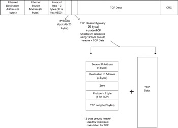
Figure 3.1: TCP/IP packets.
The Ethernet driver does not require any knowledge of the IP layer or headers, except that it needs to know that the protocol is IP, so that it can insert the correct frame type in the two-byte Ethernet type field. This can be implemented with a function call to the driver which passes the frame type and a pointer to the IP packet. The Ethernet hardware calculates the checksum for the complete Ethernet frame, including the header and transmits the entire packet over the Ethernet line via the Ethernet Media Access Control (MAC).
However, on the TCP side, the issue is more complex. Before a TCP segment (the data component of the TCP packet) can be sent, it calculates the checksum for the data in the segment. Prior to this calculation, the TCP function adds a “pseudo header” on top of the data. This pseudo header includes the source IP address and the destination IP address, along with the protocol type (number 6, which is the IP protocol type for TCP). The pseudo-header format and the TCP header are shown in Figure 3.1.
The source and destination IP addresses required by TCP for the pseudo header are the responsibility of he IP layer. With strict layering, the IP address information should not be visible at the TCP layer. However, since the TCP checksum requires these addresses, the TCP layer has to obtain the information from the IP layer—a violation of strict layering.
Performance Considerations
Consider the case of a TCP packet to be transmitted out on an Ethernet interface. The IP header is added before the TCP header, after which the Ethernet header is added before the IP header. Note that the data is provided by the TCP module and the remaining modules only add their headers before the frame. We can avoid copying the frame by creating the TCP packet such that it can accommodate the IP header and the Ethernet header. This is done by starting the TCP packet at an offset, which is calculated by adding the Ethernet header and the IP header sizes to the start of the buffer. This requires the TCP layer to have knowledge of the IP header and Ethernet header sizes—which again deviates from strict layering principles.
Hardware and System Configuration
Layering is also subject to the hardware and system configuration. For example, we may split TCP functionality to provide termination and data transfer on a line card while performing the control processing on a separate control card. Similarly, the encapsulation scheme may put a new twist on layering—there are cases where a frame relay packet may be encapsulated inside PPP (Point to Point Protocol—used on serial links to carry Layer 3 and Layer 2 traffic) and other cases where a PPP packet may be encapsulated inside a frame relay packet.
The conclusion is that while layering is a good way to partition the protocol functionality, we may not always be able to implement it in a strict fashion.
|
|
EAN: 2147483647
Pages: 126