Differences in Bus and Network Architectures
| |
Computer networks connect various devices of individual characteristics so they may communicate with one another. Some networks are peer-oriented, where all the devices are deemed equal and vie for network transport resources, transmission, and reception . Other networks (the majority of networks in use today) are hierarchical, where some devices have control and authority over other devices regarding who and how they can communicate, when they can transmit, and when and what they can receive. However, both architectures all share similar functions in that they transmit and receive data according to some type of predefined standard.
This demonstrates two distinct differences from bus architectures. First, networks have a defined transmit and receive function. This allows networks to continually pass data into the network path and receive data without regard for control and operation of the connection. This is different than a bus where strict flow control and arbitration takes place with devices assuming control over the path. Second, networks enable data transmissions over a long distance. Networks provide computers a method of transmitting and receiving data over great distances without regard to the underlying communications infrastructure. This requires network architectures to encapsulate the data to be sent over various types of media and transmission circuitry .
For the majority of networks today this is accomplished through a defined standard called TCP/IP. As we mentioned previously, this is a layered approach to communication functions that address all the requirements of transferring data from one device to another while making the communications transparent to the computers application. Figure 7-4 shows the standard layers of TCP/IP. However, underlying the complexities of these functions is the simple concept of encapsulation and transmission. TCP provides the functions for taking the data from the application and OS and wrapping them in a form that will fit into the IP envelope. IP then acts as the envelope by putting the TCP wrapper into the IP packet (nee envelope) and sending it into the network with the appropriate addressing information.
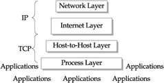
Figure 7-4: The standard TCP/IP layers and functions
The reverse happens on the receiving end. The IP functions receive packets addressed to its host device and pass these to TCP. TCP unwraps the data and presents it to the receiving application.
IP communications take place via multiple types of physical media. The media affects the integrity of the communications, the speed of the transmission, and the distances supported. Regardless of the media, the electronic standard that guides transmissions at the wire level is Ethernet. Working from packet encapsulation architecture, data packets once they hit the network vie for transmission time, resources, and priority. Obviously, the most prominent performance characteristic is the size of the packet. Packet size is determined by the implementation of Ethernet standards. These standards, as they are implemented in vendor network devices, such as NICs, switches, and routers, support this physical level of interface to the network. Capacities differ from standard Ethernet connections to the multi-gigabit capacity for Gigabit Ethernet (Gbe).
Most application transactions that access the network (this includes the application data, overhead of TCP/IP, and network error, recovery, and correction) will exceed the packet size, even for Gbe networks. So, moving data from a server to a client or from a server to a backup device can utilize larger and larger quantities of network bandwidth. Given this condition, nearly all remote application transactions will be accomplished through multiple packet transmissions.
Similar in fashion to the bus, its bandwidth, addressing, and interrupt functions also drive the network. However, major differences show up in interrupt functions (in other words, how do I get access to the network and utilize its resources?). Additional differences show up in the capacities of bandwidth, given the diversity of physical media that networks have to traverse. Physical addressing, an integral part of a networks topology, also becomes diverse, driven by the particular implementation of the networking standard a vendors devices are supporting (for example, fast Ethernet and gigabit Ethernet).
The PCI Bus
As mentioned previously, todays standard for connecting peripherals into the motherboard is the Peripheral Component Interconnect (PCI). The operation is straightforward with the PCI bus. PCI determines, through the use of the PCI controller, the destination of the data. The destination could be local or to an expansion slot. If it is destined to an expansion slot address, the host adapter takes over and translates the protocol from PCI to host adapter protocol. This could be IDE, SCSI, USB, or Firewire.
The importance of the PCI bus is that it decouples control of the data path to the PCI bus itself. Therefore, it puts more performance responsibility on the PCI bus components , and relies on its bandwidth and speed characteristics. Most PCI buses today have a 32-bit bandwidth with various clock speeds ranging from 33MHz to 1GHz. The other importance of the PCI bus is its mezzanine architecture, whereby expansion of the bus itself can take place, extending the scalability of the number of peripherals connected.
The SCSI Bus
The most popular storage bus in use today is the SCSI bus. The Small Computer System Interface (SCSI) is a standard that allows the connection of various devices through a parallel interface. Although the standard calls for support of multiple devices, general usage has been to externally connect disk and tape systems to the server. Given the bandwidth, addressability, and speed, it has become the defacto standard for the external connection of storage devices into open computing systems encompassing both UNIX and Windows.
The SCSI bus allows connections from eight to sixteen devices in a single bus. The operation is through initiator and target architecture. Only two devices can use the bus at one time. The initiator gains control of the bus and transfers the command to a device on the bus. The receiving device is the target and processes the command. It then sends a response back to the initiator. SCSI devices connected to the bus are identified by their SCSI ID, which also serves as its address. The ID identifies the devices priority for arbitration0 being lowest and 7 or 15 being the highest.
It is possible for one server to have multiple host SCSI adapters with access to multiple SCSI buses. Although these, by convention, will have different SCSI IDs, they are completely separate as they communicate through the host adapter to the PCI bus. As previously discussed, the software drivers assign the SCSI IDs. However, the SCSI controller provides the actual access to the physical device. The controller does this by assigning each device a Logical Unit Number (LUN). This, in effect, virtualizes the devices that are connected behind the controller.
Figure 7-5 depicts the most common SCSI configurations where servers with a single initiator support multiple targets (such as controllers). In this configuration, controllers support multiple LUNs or disks attached. Figure 7-6 also depicts a configuration with multiple servers supporting multiple targets. Although each target or controller is unique, multiple LUNs are addressed with similar LUN addresses. This works because the controllers own and direct each of their LUNs.
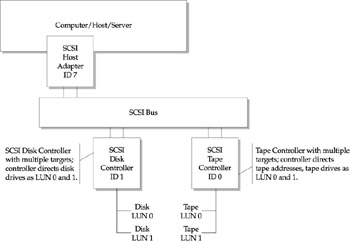
Figure 7-5: SCSI configuration single host
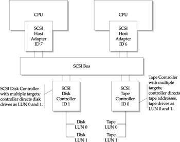
Figure 7-6: SCSI configuration multiple hosts
| |
EAN: 2147483647
Pages: 192