Lab 15c: Configuring Voice over ATM-Part II
| < Free Open Study > |
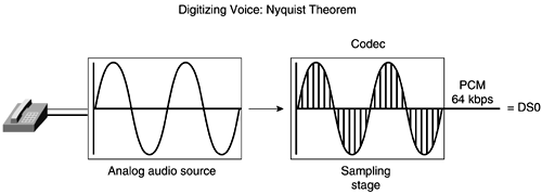
Digital Voice TechnologyDigital loop carrier technology was developed in the early 1970s with the idea of increasing transmission performance through digital technology. In addition to performance enhancements, digital technology is more reliable and easier to maintain than analog signaling. One of the key reasons for converting analog to digital is that digital signals are regenerated and do not accumulate noise in the same manner that analog signals do. Whereas analog signaling is represented as a continuous variable signal quantity such as voltage, digital signaling is represented as a sequence of binary digits indicating the presence of an electrical pulse (1) or lack thereof (0). Digitizing Analog SignalsAnalog-to-digital conversion is accomplished by a codec ( coder , decoder). Codecs are used to convert voice frequency channels to 64-kbps digital signal level 0 (DS0) channels. The codec achieves the conversion by sampling, quantizing, and encoding the signal. Before delving further into the three steps that need to be performed for analog-to-digital conversion, let's take a minute to talk about Nyquist's Theorem (see Figure 6-21). As stated in the Nyquist Theorem: Figure 6-21. Digitizing Voice: Nyquist Theorem
The highest frequency for a voice is 4000 Hzthus, 8000 samples per second, or 1 every 125 microseconds. Use the following formula to calculate the bit rate of digital voice: Analog Signal to Digital Signal Conversion ProcessNow that you have an understanding of Nyquist's Theorem, we will describe briefly the three steps of the conversion process (sampling, quantizing, and encoding), along with an optional fourth step, compression:
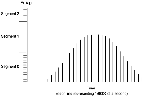
The sections that follow examine these four steps in greater detail. Sampling and QuantizationQuantization (see Figure 6-22) divides the range of amplitude values of an analog signal sample into a set of steps that are closest in value to the original analog signal. The voltage range is divided into 16 segments (0 to 7 positive and 0 to 7 negative). Beginning with segment 0, each segment has fewer steps than the previous, which reduces the noise-to-signal ratio. If there is a signal-to-noise ratio problem, it can be solved by converting PAM to PCM using a logarithmic scale. Linear sampling of an analog signal causes small amplitude signals to have a higher signal-to-noise ratio. -law and A-law are two quantization methods that help solve this problem by allowing smaller step functions at lower amplitudes. Both compress the signal for transmission and then expand the signal back to its original form at the other end. The result is a more accurate value for smaller amplitude and uniform signal-to-noise quantization ratio across the input range. Figure 6-22. Quantization Speech-Encoding Scheme The three types of speech-encoding schemes discussed here are waveform coders, vocoders, and hybrid coders. Waveform coders start with the analog waveform, taking 8000 samples per second, and then determine the most efficient way to code the analog signal for transmission. Pulse code modulation (PCM), adaptive differential pulse code modulation (ADPCM), PCM (repeated 8000 times per second for a telephone voice channel service) is the most common method for converting analog to digital. When the PCM signal is transmitted to the receiver, it must be converted back to an analog signal. This is a two-step process requiring decoding and filtering. In the decoding process, the received 8-bit word is decoded to recover the number that defines the amplitude of that sample. This information is used to rebuild a PAM signal of the original amplitude. The PAM signal then is passed through a properly designed filter that reconstructs the original analog waveform from its digitally coded counterpart . Voice-Compression TechniquesOne of the benefits of compression, of course, is to reduce bandwidth, which, in turn , reduces the time and cost of transmission. Although not necessarily pertinent on high-bandwidth LANs, you can see where this could be beneficial in a voice-over solution across a WAN. However, compression can result in distortion and delay otherwise known as echo. The two types of voice-compression techniques discussed here are waveform algorithms and source algorithms. Adaptive differential pulse code modulation ( ADPCM) is an example of waveform compression. ADPCM is a way of encoding analog voice signals into digital signals by adaptively predicting future encodings by looking at the immediate past. The adaptive part reduces the number of bits required to encode voice signals. The ITU standards for waveform compression are as follows : NOTE Remember that the standard pulse code modulation (PCM/G.711) requires 64 kbps. Two examples of source compression are Low Delay Code Excited Linear Predictive (LD CELP) and Conjugate Structure Algebraic Code Excited Linear Predictive (CS-ACELP). CELP is a hybrid coding scheme that delivers high-quality voice at low bit rates, is processor- intensive , and uses DSPs. CELP transforms analog voice signals as follows:
The ITU standards for CELP are listed here:
G.729a is a variant that uses 8 kbps, is less processor-intensive, and allows two voice channels encoded per DSP.
In summary, here is a quick recap of the compression techniques discussed:
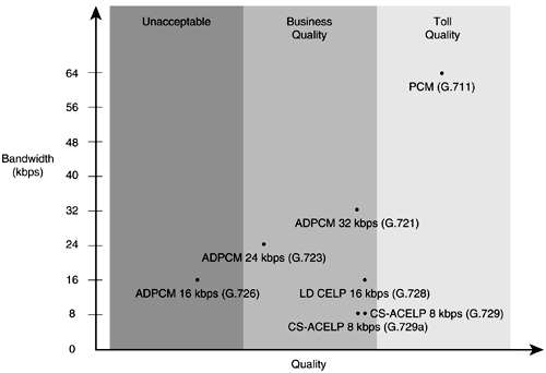
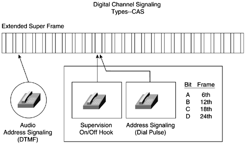
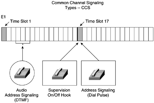
Figure 6-23 illustrates the various compression technologies, the amount of bandwidth required to set up and maintain a call with the compression, and the different categories of voice quality. Figure 6-23. Cisco's Voice-Compression Technologies Digital Speech InterpolationSimilar to statistical multiplexing, digital speech interpolation (DSI) multiplexes bandwidth among a larger number of users than there are circuits. DSI uses voice activity detection and silence suppression to allocate the silent periods in human speech and put them to active use. Remember that 50 percent of a voice conversation is silence. Mean Opinion Scoring (MOS) is a subjective method of grading telephone voice quality. The MOS is a statistical measurement of voice quality derived from a large number of subscribers judging the quality of the connection. The grading scale is 1 to 5, with 5 being excellent and 1 being unsatisfactory. Channel Signaling Types and Frame FormatsDigital service level 0 (DS-0) is the smallest unit of transmission in the hierarchy. It is a 64-kbps circuit. A DS-0 channel can carry one digital PCM voice call. A total of 24 DS-0s can be multiplexed together to form the next level, called a DS1. A digital service level 1 (DS-1) is a 1.544-Mbps circuit. A DS1 carries 24 8-bit byte DS-0s at 1.544 Mbps. A DS-1 frame is 193 bits long, containing 8 bits from each of the 24 DS-0s, plus 1 framing bit. The two major framing formats for T1 are D4 and Extended Superframe Format (ESF). D4 specifies 12 frames in sequence as a superframe. A superframe uses A- and B-bit signaling or robbed-bit signaling in frames 6 and 12 for control signaling. These robbed bits are the least significant bit from an 8-bit word. More prevalent in private and public networks is the ESF format. ESF specifies 24 frames in sequence with framing and a cyclical redundancy check (CRC). ESF also uses robbed-bit signaling in frames 6, 12, 18, and 24, also known as A B C D signaling. Like D4, these are the least significant bits in the frames. Both formats retain the basic frame structure of 192 data bits followed by 1 framing bit. The 193rd bit of each DS1 frame is used for synchronization. The European equivalent to T1/DS-1 is the E1. The E1 is composed of 32 64-kbps channels that make up a transmission rate of 2.048 Mbps. Thirty of these channels are used for voice and data. NOTE The terms DS-1 and T1 are often confused . The T1 actually identifies the physical attributes of a 1.544-Mbps transmission medium. Channel 0 is used for framing, and channel 16 is used for channel signaling. In E1 frame format, 32 time slots make up a frame. Sixteen E1 frames make up a multiframe . Two different digital channel signaling types are Channel Associated Signaling (CAS) and Common Channel Signaling (CCS) . CAS (see Figure 6-24) is signaling in which the signals necessary to switch a given circuit are transmitted through the circuit itself or through a signaling channel permanently associated with it. Figure 6-24. Digital Channel Signaling TypesCAS CCS (see Figure 6-25) is signaling in which one channel in each link is used for signaling to control, account for, and manage traffic on all channels of the link. The channel used for CCS does not carry user data. Figure 6-25. Common Channel Signaling TypesCCS |
| < Free Open Study > |
EAN: 2147483647
Pages: 283
