Security Considerations for Routing
|
EXAM 70-293 OBJECTIVE 2, 2.1.2, 3, 3.1, 5.3.1
Keep in mind that IPv4 has no default security mechanism. Unless you take security into consideration, your network will be susceptible to unauthorized monitoring and access. To prevent this, develop a strategy for your IP deployment. The following are two methods that you can use to help you enhance security when deploying IP:
-
Secure your IP packets End-to-end security requires that you not use address translation (NAT). Internet Protocol Security (IPSec) is the most efficient method of providing for a secure data stream.
-
Set up a perimeter network Use perimeter networks to help secure your internal network.
Let’s talk first about using IPSec to secure your data stream. The Windows Server 2003 IPSec protocol provides end-to-end security of your data stream using encryption, digital signatures, and hashing algorithms. IPSec resides at the Transport layer of the OSI reference model and protects the individual packets before they reach your network, removing the protection on receipt. Even data passed through from applications not having any security features can be protected using IPSec.
Keep in mind that IPSec protects the actual packets of data, not the link. Because of this, IPSec provides security even on insecure networks, and only the computers actually involved in the communication are even aware of it. IPSec provides a number of security features, including the following:
-
Authentication by using digital signatures to identify the sender
-
Integrity through the use of hash algorithms ensuring that the data has not been altered
-
Privacy through encryption that protects the data from being read
-
Anti-replay prevents unauthorized access by an attacker who resends packets
-
Nonrepudiation through the use of public-key digital signatures that prove the message’s origin
-
Dynamic rekeying to allow keys to be generated during communication, so that the different transmissions are protected with different keys
-
Key generation using the Diffie-Hellman key agreement algorithm, allowing computers to agree on a key without exposing it
-
Configurable key lengths, allowing for export restrictions or highly sensitive transmissions
The way that IPSec works is relatively simple. In order for data to be transmitted and protected between two IPSec-enabled computers, the computers must agree on which keys, mechanisms, and security policies will be used to protect the data. This agreement, or negotiation, produces a security association (SA).
The first SA established between the two computers, called Internet Security Association and Key Management Protocol (ISAKMP), provides the method of key exchange. Using ISAKMP to provide protection, the two computers negotiate the production of a pair of IPSec SAs and keys: one for inbound transmissions and one for outbound transmissions. These SAs include the agreed-upon algorithm for encryption and integrity and the agreed-upon IPSec protocol to use. Two IPSec protocols can be used:
-
Authentication Header (AH) Provides data authentication, integrity, and anti-replay to IP packets.
-
Encapsulating Security Payload (ESP) Provides confidentiality, along with data authentication, integrity, and anti-replay to IP packets.
Using the IPSec SAs and keys, the two computers protect the data during transmissions.
The second method that you can use to enhance security is a perimeter network. These are also sometimes called a demilitarized zone (DMZ) or a screened subnet. This type of network is generally an additional network between the protected network and the unprotected network. These types of networks are usually small LANs connecting border routers with internal routers. Servers that are required to be exposed to the Internet, like your Web server or mail server, can be placed in the DMZ and be protected by a firewall. Then additional firewalls are placed between the DMZ and your network. Figure 4.40 demonstrates how this type of configuration might look.
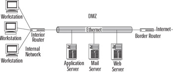
Figure 4.40: A Perimeter Network or DMZ
Analyzing Requirements for Routing Components
A router is nothing more than a very specialized computer. It’s made up of the following elements:
-
A central processing unit (CPU)
-
Random access memory (RAM)
-
Input/output system (BIOS)
-
Operating system (OS)
-
A motherboard
-
Input/output (I/O) ports
-
A power supply
-
A case to hold all of this
Most of these parts remain hidden, but that’s okay because these components are generally extremely reliable. Most of the time, you won’t need to worry about them at all. The components that you will have the most interaction with are the operating system and the I/O ports.
As you know, the operating system is the software that controls the various hardware components and makes the computer usable. The router usually has a configuration file that includes the number, location, and type of each I/O port, as well as details about bandwidth, addressing, and security.
The I/O ports are the one component that you will get to know on a personal basis. These ports function like NICs, in that they define the medium and framing mechanisms and provide the appropriate physical interfaces.
Simplifying Network Topology to Provide Fewer Attack Points
Attacks on your network can come in a variety of ways, in both active and passive forms. An active form of attack is launched with the purpose of damaging or destroying your data and/or your network infrastructure. Passive attacks, on the other hand, can be thought of more along the lines of “fishing expeditions.” In these situations, the attackers are mostly snooping—just looking around.
One of the best defensive postures against both forms of attacks is to limit the paths to your network an attack can take. You can accomplish this by implementing three simple tactics:
-
Minimize the number of network interfaces through which the attack may come
-
Minimize the number of routes over which the attack may come
-
Minimize the number of routing protocols through which the attack may come
Most router attacks involve the manipulation of the routing table entries so that service to legitimate systems or networks is denied. RIP version 1 and Border Gateway Protocol (BGP) offer no or little authentication, and what little they do offer usually isn’t implemented. This offers the perfect target for attackers to alter legitimate routes, often by spoofing their source IP address and creating a denial-of-service (DoS) condition. The easiest remedy is to use whatever tools you have available: if your routing protocol offers authentication, implement it. If it doesn’t, consider changing to one that does.
Minimizing the Number of Network Interfaces and Routes
You want to limit the number of network interfaces through which an attacker could gain entrance. Every NIC you have exposed to the Internet is a potential doorway through which someone could enter. The fewer interfaces exposed, the less work for you in preventing someone coming through an open port and wrecking havoc on your network.
Minimizing the number of routes an attacker might take to your network is similar to minimizing the interfaces. You are restricting the paths through which an attack may come.
Minimizing the Number of Routing Protocols
You also want to limit the options of attackers if they do manage to gain access to your network. By reducing the number of routing protocols, you reduce the options available to the attacker.
Demand-dial routing allows you to use impermanent, dial-up WAN lines to exchange data between two networks. It allows for the effective use of these impermanent connection methods, such as analog modems and ISDN, to mimic dedicated Internet connections. Demand-dial routing brings up the connection only when outbound traffic is addressed to an associated link. With a demand-dial connection, you can use additional leased lines to add needed bandwidth at peak use times. However, you should check all the potential costs before you choose this alternative, to avoid any unexpected and unpleasant surprises when the telephone bill arrives.
Demand-dial routing concepts are relatively simple. A link is created when needed, and the connection is dropped when it’s no longer needed. There are three basic phases of demand-dial connection setup:
-
Configure the first router to initiate and receive demand-dial connections from the second router.
-
Configure the second router to initiate and receive demand-dial connections from the first router.
-
Initiate the demand-dial connection from the first router to the second router.
Adding a Demand-Dial Interface
Although the three phases for setting up a demand-dial connection are relatively straightforward, actually setting up a demand-dial interface can be a complex and lengthy process. Make sure you double-check your work as you go along, because troubleshooting at a later phase could be extremely difficult and complicated. To set up the interface, follow these instructions:
-
Select Start | Administrative Tools | Routing and Remote Access.
-
In the console tree on the left side of the window, click the appropriate server or router.
-
Right-click Network Interfaces, as shown in Figure 4.41, and choose New Demand-dial Interface from the context menu.
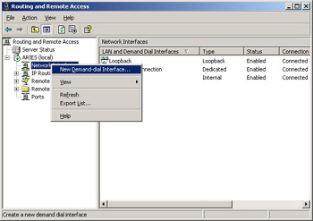
Figure 4.41: Choose New Demand-dial Interface -
The Demand-Dial Interface Wizard starts. Click Next in the Wizard’s first window.
-
The next window asks for a name for this demand-dial interface. The default name is Remote Router, as shown in Figure 4.42. You might want to use a more descriptive name, such as the name of the branch office or the name of the network to which you are connecting. When you’ve named the interface, click Next again.
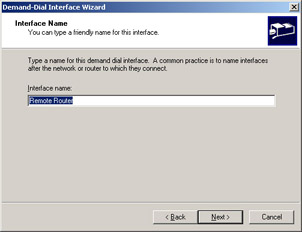
Figure 4.42: Choose an Appropriate Interface Name -
You’re now confronted with three choices of connection type. For our purposes of adding a demand-dial interface, the first two choices are the only ones we will deal with. If your computer doesn’t have one of these, that specific option will be grayed out and unavailable.
-
Connect using a modem, ISDN adapter, or other physical device Choose this option, and then click the Next button. Choose which modem you want to use, and then enter the telephone number you want to be dialed. Notice that in addition to the primary number, you can also click Alternatives and enter other numbers to be tried automatically if the primary number cannot be reached.
-
Connect using virtual private networking (VPN) If you select this option and click Next, the VPN Type window opens. Choose the tunneling protocol you want to use, and click Next again. Finally, in the Destination Address window, provide either the host name or the IP address for the remote router and click Next again.
-
-
Under Protocols And Security, choose all the conditions that will apply to the connections. If you have chosen to connect using a modem, ISDN device, or other physical device, you will have two options here. This second option will not be available if you have chosen the VPN option earlier. If you choose both options, the wizard will present you with a window to configure each of the items.
-
Add a User Account So A Remote Router Can Dial In
-
Use Scripting to Complete The Connection With The Remote Router
-
-
In the next window, fill in the IP address of the network or networks you want to access.
-
The next window asks you to provide the user account and password as your Dial Out Credentials. This will complete the Wizard, and a new routing interface will be added in the Routing and Remote Access window.
Router-to-Router VPNs
Take two separate networks and put the Internet between them. Now, connect them using a tunnel through the Internet. You create this tunnel using the Point-to-Point Tunneling Protocol (PPTP) or Layer Two Tunneling Protocol (L2TP), so that the data being exchanged between the two networks is encrypted. But what’s the difference between a normal client VPN connection and this type of VPN? What can you use to connect the two networks together? You can use routers.
You can use a router-to-router VPN to connect two separate networks together over the Internet and still maintain security. Before we get into the specifics of setting up a router-to-router VPN, let’s look briefly at how to set up a client VPN connection first. That way, you will understand the difference between the two and why you might want to use one over the other. The first step is to turn on the Windows Server 2003 VPN Server.
Exercise 4.04: Installing and Enabling Windows Server 2003 VPN Server
Installing and setting up a Windows Server 2003 VPN Server is simple. Just follow these steps:
-
Select Start | Administrative Tools | Routing and Remote Access. If you have not set up RRAS, you’ll see a red circle in the server icon. If you have set up your server to be a VPN server when you were installing the Windows Server 2003 software, you will see a green arrow, as shown in Figure 4.43.
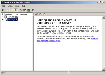
Figure 4.43: RRAS Has Already Been Turned On -
If the service has already been turned on, you may want to reconfigure your server. You can reconfigure it by right-clicking the server icon and choosing Disable Routing and Remote Access. Click Yes to continue when you are prompted. Your server icon should now have the red circle rather than the green arrow.
-
Right-click your server’s icon and choose Configure and Enable Routing and Remote Access to start the Setup Wizard. Click Next to continue.
-
Select the Remote Access (dial-up or VPN) option, as shown in Figure 4.44, and then click the Next button.
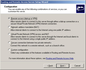
Figure 4.44: Choose Remote Access -
Check the VPN check box, and then click the Next button.
-
In the VPN Connection window, shown in Figure 4.45, select the network interface that is connected to the Internet, and then click the Next button.
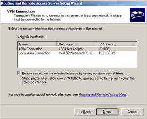
Figure 4.45: Choose the Interface Connected to the Internet -
In the IP Address Assignment window, you have two choices:
-
Automatically Choose this option if you have a DHCP server you can use to automatically assign IP addresses to the remote clients. This setup will be easier to administer than assigning addresses manually. (However, if you do not have a DHCP server, you must specify a range of static addresses.) Click Next to continue.
-
From a specified range of addresses Choose the option if the remote clients can only be given an address from a specified pool of addresses. Click Next to continue. In the Address Range Assignment window, click the New button. In the Start IP address box, type the first IP address in the range of addresses you want to use. Then type in the last IP address in the range you’ve chosen. Windows Server 2003 will automatically calculate the number of addresses for you. Click the OK button to return to the Address Range Assignment window, and then click the Next button to continue.
-
-
In the next window, accept the default value of No, use Routing and Remote Access to authenticate connection requests, and click the Next button to continue.
-
Click Finish to turn on RRAS and to configure the server as a remote-access server.
Once you have your server set up to provide VPN service (completed Exercise 4.04), you can allow client machines to connect to it over the Internet.
Configuring a VPN Connection from a Client Computer
To configure a VPN connection from a client computer, you must first be logged on as the Administrator or as a member of the Administrators group. The following steps will vary depending on which version of Windows the client computer has installed.
-
Make sure that you have a correctly configured Internet connection on the client computer.
-
Select Start | Control Panel | Network Connections | Create a New Connection. This opens the New Connection Wizard. Click the Next button to continue.
-
Click the Connect To The Network At My Workplace option, and then click the Next button.
-
Choose Virtual Private Network Connection, and then click Next.
-
Type in a description name in the Company Name text box and click Next.
-
Choose Do Not Dial The Initial Connection. If the computer isn’t always connected to the Internet, you should probably choose Automatically Dial This Initial Connection, click the name of the connection to the ISP, and click Next.
-
Type in the IP address or the host name of the VPN server computer to which you are connecting.
-
Depending on if you want anyone to be able to have access to this VPN connection of just yourself, choose Anyone’s Use or My Use Only, and then click Next.
-
Click the Finish button and save the connection information.
-
Choose Start | Control Panel | Network Connections again and double-click the new connection you just created.
-
Go to Properties and configure the options for this connection you want. If you’re connecting to a domain, click the Options tab and select the Include Windows Logon Domain check box, so you can specify that you want to request Windows Server 2003 logon domain information before trying to connect. Another option you’ll probably want to select is the Redial If Line Is Dropped check box on the Options tab.
Using your new VPN connection is simple: click Start | Connect To and choose your new connection. If you don’t already have a current connection to the Internet, you’ll be offered the opportunity to connect. When the connection is made, the VPN server will prompt you for your name and password. Enter the necessary information and click the Connect button. All of the same resources available when you are directly connected to the network are available now. When you’re ready to disconnect, simply right-click the connection and choose Disconnect.
Now that you know how to create and use a client VPN connection, what are the differences in setting up a router-to-router VPN? There are actually not very many differences.
Exercise 4.05: Setting up Windows Server 2003 as a Router-to-router VPN Server
The differences in the setup of Windows Server 2003 as a router-to-router VPN server and as a static router (Exercise 4.1) are minimal. Follow these steps:
-
Select Start | Administrative Tools | Routing and Remote Access.
-
Right-click your server’s icon and choose Configure and Enable Routing and Remote Access to start the Setup Wizard. Click Next to continue.
-
Select the Secure connection between two private networks option, as shown in Figure 4.46, and then click the Next button.

Figure 4.46: Choose Secure Connection between Two Private Networks -
Choose the No option when you are asked if you want to use demand-dial connections, unless you need to use them, and then click the Next button again. If you choose Yes to use demand-dial connections, you’ll have the opportunity to set up the demand-dial connections when this Wizard is finished. If you are using a full-time connection, you don’t need the demand-dial connection.
-
Click Finish to turn on RRAS and to configure the server as a router-to-router VPN server.
Make sure you have addresses assigned to all the installed interfaces and that you’ve installed and set up your routing protocols on each interface. Then you should be able to use this router.
Packet Filtering and Firewalls
One of the best features available in RRAS is the ability to filter TCP/IP packets traveling in either direction. For all practical purposes, enabling packet filtering creates a firewall on your server. You can build filters that can either allow or deny packet traffic into or out of your network. You do this by specifying rules that designate source and destination addresses and ports.
Normally, you set up these filters to block information that the machines in your network should not receive. The filters are set up on a specific interface. This means that the filters on one interface are completely independent of the filters on another. Incoming and outgoing filters are independent of one another also.
Simply put, you have two choices with input filters: accept all traffic over the interface except the traffic you specify, or drop all traffic except the traffic you specify. Output filters are configured in the same manner. Which choice you should make most often depends on the context and purpose of the filter. The second option is the most secure. If you are attempting to keep all but very specific traffic out of your network, this would be the correct choice. The first choice is appropriate if you are just trying to stop specific traffic.
For instance, say you have a Web server and the only traffic you want to allow on this server is traffic traveling to and from the Web server service. All you need to do is configure an input filter for the destination IP address of the Web server and the TCP destination port 80. At the same time, you will want to configure an output filter for the source IP address of the Web server and the TCP source port 80. If these two filters are the only two filters operational on this server, the only traffic that will be allowed across the interface is TCP traffic to and from the Web server service on your Windows Server 2003 machine.
You need to be careful about how you implement these filters, so that you don’t make them too restrictive, which would impair the functionality of the other protocols operating on the server. For instance, given our example of a Web server, we can’t use PING or any other basic IP troubleshooting tool on that computer now, because we’ve restricted it to only Web traffic on port 80. We’ll talk more about troubleshooting shortly.
| Test Day Tip | Know how to set up both inbound and outbound TCP/IP packet filters. Understand that you can accept all but those IP addresses you want to reject, or you can deny all except those IP addresses you wish to accept. |
It’s a good idea to use packet filtering to block unwanted traffic from your VPN servers. There are two basic sets of rules for this process: PPTP packet filters and L2TP packet filters.
For PPTP, there are at least two filters that are required to block non-PPTP traffic. You need to allow Generic Routing Encapsulation (GRE) packets to pass. You also need to allow inbound traffic on TCP port 1723. If the PPTP server is also acting as a PPTP client, you can add a third filter to allow outbound traffic on TCP port 1723 also. After these packets are established, choose the Drop All Packets Except Those That Meet The Criteria Below radio button. Then close the dialog box. Repeat the process on the output side.
For L2TP packet filters, you will need four filters: two for input and two for output, as follows:
-
A filter with the VPN interface address and a network mask of 255.255.255.255, filtering the User Datagram Protocol (UDP) with a source and destination port of 500
-
An input filter with a destination of the VPN address and a network mask of 255.255.255.255, filtering UDP traffic with a source and destination port of 1701
-
An output filter with a source of the VPN interface address and a network mask of 255.255.255.255, filtering UDP traffic with a source destination of 500
-
An output filter with a source of the VPN interface address and a network mask of 255.255.255.255 filtering UDP with a source and destination port of 1701
Test Day Tip Make sure you know how to filter all packets except VPN traffic on a PPTP or L2TP server. Make sure you understand the process and the number of filters each protocol requires.
Logging Level
Coming up with a good logging strategy is important for the proper maintenance of your network and the devices that are used on it. Deciding what to log is probably one of the most important questions you will consider. If you have too much logging, the performance of your server and the network will decline sharply. If you have too little logging, when you have a problem, you won’t have the information you need to determine the source and cause. The best choice is to log only those options you really need, and when you don’t need a particular type of log data anymore, stop recording it.
In order to set the logging levels, open the RRAS module, right-click the server you wish to administer, choose Properties, and then click the Logging tab. As shown in Figure 4.47, the Logging tab contains several options for the various types of events that you can log. The default is to log all errors and warnings. You can also check the Log additional Routing and Remote Access information (used for debugging) check box, which, as its name implies, will assist you in debugging.
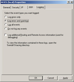
Figure 4.47: Set the Logging Level
|
EAN: 2147483647
Pages: 173