Planning an IP Addressing Strategy
|
EXAM 70-293 OBJECTIVE 2, 2.1, 2.1.2
Before you can implement an IP network infrastructure, there are many details that you must consider. Here, we will take a look at how to plan your network by identifying the appropriate addressing requirements and limitations that will shape the network. Understanding subnetting is a requirement to implement your addressing scheme. You will need to identify hardware requirements, decide what class of address you will need, and determine if access to the Internet is necessary for all or just some of your hosts.
Subnetting will allow you to create logical segments on your network that will overlay the physical topology. By using a well-planned subnetting scheme, you can handle your current needs and plan for expansion for future needs. You can also make use of these segments to isolate and distribute heavy traffic, without having a major impact on other segments of your network.
Analyzing Addressing Requirements
EXAM 70-293 OBJECTIVE 2.1.1
Every device on a TCP/IP-based network that has a network interface is referred to as a host. Each host must have a unique IP address. The most common analogy used to describe an IP addressing scheme is that of a street (subnetwork) with many houses (hosts). Each house (host) must have a unique address (IP address) on its street. Visualize a situation in which you are a city planner. In this analogy, the city is the entire corporate network, each street is a subnetwork, and each house is a host.
Our city, illustrated in Figure 3.9, needs streets for all of the houses for the current residents. Additionally, we might require more houses to be built for new residents. We must design the streets in such a way that will allow for traffic flow to be regulated and to minimize congestion. Also, we do not want to have so many streets that we can build only a few houses on each street before we run out of room in our city. We know that it might not be an effective use of our resources if we build a major thoroughfare and a lot of apartments in an area of the city that will have only a few residents. Some parts of our city need access to the “super highway”—the Internet or WAN—so the residents can get to other cities. We can use this example to get a concept of how to design and plan for a TCP/IP network.
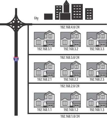
Figure 3.9: IP City
Since the host IP address must be unique, the simple rule to calculate the number of hosts for our network is one IP address per host, plus one IP address for each additional network adapter in a host machine. We have a concept of one network in the corporate sense, but when determining address requirements, there are a few more details we must consider.
You can define IP addresses using one of the three classes available for standard IP communications: Classes A, B, and C. Before we decide which class to use, we need to determine the type of network we are implementing and how many hosts there are per segment.
| Exam Warning | You should know the IP address classes and their ranges, the default mask for each class, and the number of hosts each class can support. |
Creating a Subnetting Scheme
EXAM 70-293 OBJECTIVE 2.1.3
IP addresses are 32-bit values, often referred to as dotted quads. Each bit is a binary value of either 0 or 1. Since there are 8 bits, there are 28 combinations of 0 and 1, which equals 256 combinations, allowing for a range of 0 to 255. An address is broken down into octets consisting of four 8-bit sections. An address is usually represented by a decimal number such as 141.59.115.7, which is equal to the binary number of 10001101.00111011. 01110011.00000111. Computers process only binary information, but we convert it to decimal because that is easier for us human beings to work with.
Classful Addressing
As mentioned, host addresses can belong to one of three classes of IP address, and each has a range of addresses. The range is defined by the value of the first octet. Table 3.3 shows the classes and their ranges, as well as the binary representations of the ranges. Classes D and E are also classes of IP addresses, but Class D is restricted to multicasting and Class E addresses are reserved for future use. 127.0.0.0 is reserved for connectivity testing. 127.0.0.1 is a special address that represents the local loopback adapter that resolves as localhost. We can ping the local host to troubleshoot the protocol stack. We will discuss this in more detail in the “Troubleshooting IP Addressing” section later in this chapter. Each class also has a default subnet mask.
| Class | Range of Values | Default Mask | Networks | Hosts | Binary |
|---|---|---|---|---|---|
| A | 0 to 126 | 255.0.0.0 | 126 | 16,777,214 | 00000001 to 01111110 |
| B | 128 to 191 | 255.255.0.0 | 16,384 | 65,534 | 10000000 to 10111111 |
| C | 192 to 223 | 255.255.255.0 | 2,097,152 | 54 | 11000000 to 11011111 |
| D | 224 to 239 | Not applicable | Not applicable |
| Test Day Tip | In Table 3.3, notice that the first two bits of the first octet in each class also define the top of the range of network IDs for that class. If you take the first two bits of Class A, 01, and add the remaining six digits as ones you get 01111111, or 127. Remember that 127 is reserved, so 126 is the highest value for the network ID of a Class A network. Class B is 10 (101111111 = 191), and Class C is 11 (11011111 = 223). |
The default mask for each class defines the number of networks and the number of hosts for each network. An IP address contains information about the network on which the host resides, and the address of the host. The network ID is the reference to the logical subnet, and it refers to the octets that are predefined as the network ID and implemented with the default mask. The remaining octets are for the hosts. Figure 3.10 illustrates the network and host IDs.
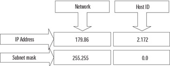
Figure 3.10: Network ID and Host ID
The first address in each network refers to “this network” (itself), such as 24.0.0.0/8 or 204.79.26.0/24. The last address in each network or subnetwork is the broadcast address for that segment, such as 179.54.255.255 or 204.79.26.255. We can derive the formula for determining the number of hosts per network as 2n – 2, where n is the number of bits available for host IDs. In Figure 3.10, we are using a subnet mask of 255.255.0.0, so the last two octets, or 16 bits, are available. If we plug that into the formula, we get 216 – 2 = 65,534 hosts per network.
Class A addresses are used for networks that have a large number of hosts. Based on the default mask, we have the first octet for networks and the last three for hosts. So, we have 126 networks and 224 – 2 hosts, or 16,777,214. Likewise, with class B, the default mask is 255.255.0.0, so the first two octets are for the network IDs, for a total of 16,384, and the last two are for the hosts. So, class B networks have 216 – 2 hosts, or 65,534. Class C networks have more networks but are smaller, with 28 – 2 hosts, or 254.
We could implement our network now very simply. Determine the number of hosts and the number of networks, and pick the class that fits. If you do not wish to assign a public IP address to all your machines, there is another solution. There are three banks of IP addresses that are called private IP address ranges. They are listed in Table 3.4. Typically, a network will need only one or two public addresses for the Internet interfaces, and everything internal to the company can use the private IP addresses internally.
| Network ID | Subnet Mask | Range |
|---|---|---|
| 10.0.0.0 | 255.0.0.0 | 10.0.0.1 to 10.255.255.254 |
| 172.16.0.0 | 255.240.0.0 | 172.16.0.1 to 172.31.255.254 |
| 192.168.0.0 | 255.255.0.0 | 192.168.0.1 to 192.168.255.254 |
Understanding ANDing and Binary Numbering
Once we define our subnetworks, the machines will need to communicate with other machines on the network. The determination of the host as a local or remote destination is derived by applying the subnet mask of the source host to the IP address of the destination. This process involves applying a Boolean logic method called ANDing. By ANDing the binary representation of an address and a subnet mask, the IP layer can determine if the address is on the same logical network or a different one.
In Table 3.5, we have a source and a destination host address. First, the subnet mask is applied to the source address using Boolean AND logic. To perform the AND operation, start from the left and compare each bit in the binary numbers representing the IP address and the subnet mask. If both are 1 (1 AND 1), then the result is 1; otherwise, the result is 0. After the comparison is performed with each address, if the resulting binary values are equal, then the addresses are on the same network; if they are not equal, then they are on different logical networks.
| Source IP Address 172.16.5.16 | Destination IP Address 172.16.2.251 |
|---|---|
| 10101100.00010000.00000101.00010000 | 10101100.00010000.00000010.11111011 |
| 11111111.11111111.11111110.00000000 | 11111111.11111111.11111110.00000000 |
| 10101100.00010000.00000100.00000000 | 10101100.00010000.00000010.00000000 |
We can use the default subnet masks to define our network, or we can use a custom subnet mask. The ability to define the subnet mask allows us to take the default network definition and “borrow” bits from the available hosts on that network in order to create smaller logical networks, or subnets.
Exercise 3.03: Fun with Binary Numbers
In this exercise, you will use the scientific mode of Windows Calculator to convert binary numbers to decimal numbers and vice versa.
-
Select Start | Run and type calc to launch Windows Calculator.
-
Select View | Scientific.
-
Make sure the Dec radio button is selected.
-
Using the keypad, enter the number 175.
-
Click the Bin radio button. You should see 10101111.
-
In the edit box, type 11000111.
-
Click the Dec radio button. You should see 199.
-
Type 75 in the edit box, and then click the Bin radio button.
-
Notice the binary number is 1001011. Count the number of bits. There are only 7 bits in the result. Calculator will strip leading zeros from binary values, so it is important to always “pad” the binary numbers to 8 bits when using them for IP address functions. The correct representation for 75 as an IP address octet is 01001011.
-
Use Windows Calculator to convert the binary representation of the following IP addresses to decimal IP addresses.
Binary
Decimal
11001010.01000101.01001111.00110101
10001001.00001101.10101010.11111001
11000111.01011111.01000000.10000001
11000011.11011101.11101111.00000101
00000111.11100010.00100000.11111101
10000001.00100101.00001111.10110001
10000011.01000100.00100000.00010110
-
Use Windows Calculator to convert the following decimal IP addresses to a binary representation of IP addresses.
Decimal
Binary
192.178.44.121
204.18.1.179
10.2.2.76
141.22.94.107
55.87.191.11
187.34.59.199
99.107.253.224
You might begin to notice patterns with binary numbers. The values of each placeholder are similar to the decimal format, except that decimal is base 10. The first digit in a decimal number is 100, or 1; the second is 101, or 10; the third is 103, or 100; and so on. 111 in decimal is equal to 100 + 10 + 1.
In binary representation, each placeholder is base 2, so the first digit in a binary number is 20, or 1; the second is 21, or 2; the third is 22, or 4; and so on. Thus, 111 in binary is equal to 4 + 2 + 1, or 7. Table 3.6 shows a quick summary of one octet in binary.
| 128 | 64 | 32 | 16 | 8 | 4 | 2 | 1 |
| 27 | 26 | 25 | 24 | 23 | 22 | 21 | 20 |
| Test Day Tip | Binary math got you down? Never fear, the standard Windows Calculator will be available for you to use during the exam. It is a good idea to be proficient with the use of the Calculator program in scientific mode, so that you don’t have any doubts during the exam. Be very careful to count your digits in binary results. There are no leading zeros, so 1111111 is actually 011111111, 111111 is actually 00111111, and so on. Despite the convenience of using the Calculator program, you should still understand how to convert binary to decimal manually. |
Subnetting Networks
Subnetting networks is necessary to efficiently manage network resources and control traffic on your network. When your network has grown beyond the capacity of your current infrastructure, you must change your configurations to support those changes. It is relatively simple to identify limitations that are obvious, such as the number of networks and hosts.
You can determine the number of networks by counting the number of physical locations that will need a router to connect them to other locations, such as another building or another floor in the same building. You can estimate the number of hosts needed per network by counting all the IP-based resources in each physical location, including printers, desktops, servers, and other routers. Once you have that information, you can decide which class of network to use and how to break down that network into logical subnets that will be used to implement each physical or logical location. To summarize, there are three steps to subnetting:
-
Identify the number of hosts.
-
Identify the number of networks.
-
Use an assigned IP network ID or choose a private IP address, and then determine how to subnet your network.
As an example, suppose that we have 55 employees in one location, with 12 IP-based network printers, 6 servers, and 1 Internet refrigerator that orders the groceries in the break area when the stock is depleted. Our IP address block assignment provided by our Internet Service Provider (ISP) is 204.74.9.0/24. All the employees are currently located in one large, central area on the same floor. Since we have no physical boundaries to overcome, we use the default subnet mask. This would provide us with one network and 8 bits in the host portion of our address. The 8 bits give us 256 hosts, but the first host is 0, which refers to our network, and the last host is the broadcast address for the network, 255. Remember the formula is 2n – 2, where n is the number of bits available for host IDs. So, 28 – 2 = 256 – 2 = 254 hosts per network. Since we have 74 hosts and one router, that is a total of 75 host IDs. We have plenty of room for growth, and the scheme is simple.
The first address on our network starts at 204.74.9.1 (remember 0 is “this network”) and continues to 204.74.9.254 with a subnet mask of 255.255.255.0. Table 3.7 shows an example of the network portion of our address, 204.74.9, and the host portion in the last octet, from 1 to 254.
| Source IP Address 204.74.9.21 | Destination IP Address 204.74.9.209 |
|---|---|
| |--—— Network ID ——--|. |— Host —| | |——— Network ID ——|. |— Host —| |
| 11001100.01001010.00001001.00010000 | 11001100.01001010.00001001.11010001 |
| 11111111.11111111.11111111.00000000 | 11111111.11111111.11111111.00000000 |
| 11001100.01001010.00001001.00000000 | 11001100.01001010.00001001.00000000 |
Notice how the results of the subnet mask are equal? Of course, this is a simple example, and we can see just by the address and subnet mask that they are both on the same network.
Now we move into the new building where everyone gets his or her very own office. The office has three stories, so we need to break up our simple network into three segments to route between floors. We must use the same IP address block provided. One option is to borrow bits from the host IDs and create more subnetworks. The number of subnets is determined by the value of the bits that we borrow from the host IDs. In the example in Table 3.8, we have used 2 bits, shown in bold. The last octet of the subnet mask is now 11000000, or 192. The number of hosts per network is 26 – 2, or 62. That should be more than sufficient, so our limitation is the number of networks.
| Source IP Address 204.74.9.21 | Destination IP Address 204.74.9.209 |
|---|---|
| |———— Network ID ———|. |—Host —| | |———— Network ID ———|. |—Host —| |
| 11001100.01001010.00001001.00010000 | 11001100.01001010.00001001.11010001 |
| 11111111.11111111.11111111 .11000000 | 11111111.11111111.11111111.11000000 |
| 11001100.01001010.00001001.00000000 | 11001100.01001010.00001001.11000000 |
To determine the number of networks we have, we take the bits 11 and use the formula 2n – 22, which is 4, so we can have up to four networks. We can create a list of the networks, convert them to decimal, and get the hosts for each network, as shown in Table 3.9. Remember that the first and last hosts for each network are not assignable.
| Subnet | Range | Hosts |
|---|---|---|
| 1 | 00000001 to 00111110 | 204.74.9.1 to 204.74.9.62 |
| 2 | 01000001 to 01111110 | 204.74.9.65 to 204.74.9.126 |
| 3 | 10000001 to 10111110 | 204.74.9.129 to 204.74.9.190 |
| 4 | 11000001 to 11111110 | 204.74.9.193 to 204.74.9.254 |
Each network has 62 hosts, and there are 4 networks, so we still have 248 hosts to grow into.
We could expand this example by adding satellite offices. Without redesigning the entire subnet, we could use one of the networks that was not used in the example and subnet it further. This is called variable-length subnetting. One of the networks would be broken down into two smaller networks with 30 hosts by borrowing another bit. The networks would have the notation 204.74.9.0/27 and 204.74.9.33/27. The hosts for 204.74.9.0/27 are 204.74.9.1 to 204.74.9.30, and the hosts for 204.74.9.33/27 are 204.74.9.34 to 204.74.9.63.
| Test Day Tip | If you want to use the first and last networks in this scenario, you must use Classless Inter-Domain Routing (CIDR) notation and use routing services that support CIDR. In traditional subnetting, the first network ID is all zeros, so it is “this network,” and the last network ID is all ones, which signifies the broadcast for that network. |
Classless Inter-Domain Routing (CIDR)
You should see now that there are limits to the size of the network you can implement using classful IP address assignment. It has become necessary to provide more options to create larger segments to reduce the size of routing tables and overcome the depleted public IP address pool. The solution is known as Classless Inter-Domain Routing (CIDR). CIDR uses a binary format to provide the definition of network addresses.
Use the matrix in Table 3.10 to quickly identify routing and subnet information based on your requirements for the number of hosts and networks. The column of binary masks should help you calculate the networks for each subnet, and the table shows how the classful addressing scheme relates to the CIDR notation.
| Required Networks | CIDR | Binary Mask | Hosts per Subnet (2n–2) | Subnet Mask |
|---|---|---|---|---|
| 256 Class B | /8 | 11111111.00000000.00000000.00000000 | 16,777,212 | 255.0.0.0 |
| 128 Class B | /9 | 11111111.10000000.00000000.00000000 | 8,388,606 | 255.128.0.0 |
| 64 Class B | /10 | 11111111.11000000.00000000.00000000 | 4,194,302 | 255.192.0.0 |
| 32 Class B | /11 | 11111111.11100000.00000000.00000000 | 2,097,150 | 255.224.0.0 |
| 16 Class B | /12 | 11111111.11110000.00000000.00000000 | 1,048,574 | 255.240.0.0 |
| 8 Class B | /13 | 11111111.11111000.00000000.00000000 | 524,286 | 255.248.0.0 |
| 4 Class B | /14 | 11111111.11111100.00000000.00000000 | 262,142 | 255.252.0.0 |
| 2 Class B | /15 | 11111111.11111110.00000000.00000000 | 131,070 | 255.254.0.0 |
| 1 Class B | /16 | 11111111.11111111.00000000.00000000 | 65,534 | 255.255.0.0 |
| 256 Class C | /16 | 11111111.11111111.00000000.00000000 | 65,534 | 255.255.0.0 |
| 128 Class C | /17 | 11111111.11111111.10000000.00000000 | 32,766 | 255.255.128.0 |
| 64 Class C | /18 | 11111111.11111111.11000000.00000000 | 16,382 | 255.255.192.0 |
| 32 Class C | /19 | 11111111.11111111.11100000.00000000 | 8190 | 255.255.224.0 |
| 16 Class C | /20 | 11111111.11111111.11110000.00000000 | 4094 | 255.255.240.0 |
| 8 Class C | /21 | 11111111.11111111.11111000.00000000 | 2046 | 255.255.248.0 |
| 4 Class C | /22 | 11111111.11111111.11111100.00000000 | 1022 | 255.255.252.0 |
| 2 Class C | /23 | 11111111.11111111.11111110.00000000 | 510 | 255.255.254.0 |
| 1 Class C | /24 | 11111111.11111111.11111111.00000000 | 254 | 255.255.255.0 |
| 1/2 Class C | /25 | 11111111.11111111.11111111.10000000 | 126 | 255.255.255.128 |
| 1/4 Class C | /26 | 11111111.11111111.11111111.11000000 | 62 | 255.255.255.192 |
| 1/8 Class C | /27 | 11111111.11111111.11111111.11100000 | 30 | 255.255.255.224 |
Troubleshooting IP Addressing
EXAM 70-293 OBJECTIVE 2.6
The flexibility of TCP/IP also contributes to the complexity of troubleshooting addresses and connections. There are several tools that can help isolate and identify issues with addressing, but it is also imperative that you understand IP addressing rules and subnetting. The ipconfig, ping, and tracert commands are the most useful tools for identifying addressing problems with client configurations and connections to other hosts on the Internet.
Client Configuration Issues
EXAM 70-293 OBJECTIVE 2.6.1
Some of the issues that occur with manual configuration of IP addresses include duplicate addresses, invalid subnet masks, invalid default gateways, and invalid or missing host name resolution settings (such as DNS and WINS). To help identify the problem, start by typing ipconfig /all at a command prompt. Verify the information that is output by the command is correct, and then continue by using ping to help isolate the problem.
-
Ping the loopback address (127.0.0.1) to verify that the TCP/IP protocol stack is configured correctly on the local computer.
-
Ping the external IP address of the local computer to ensure the host is on the network and using a valid IP address; that is, there are no address conflicts.
-
Ping the IP address of the default gateway to verify that the default gateway is accessible and your local network configuration contains the correct subnet mask.
-
Ping the IP address of a remote host to verify that you can transmit data over the default gateway.
If you are not able to get traffic through to a site, but you are making it through the default gateway, you should use tracert to identify the break in the route to the destination.
DHCP Issues
EXAM 70-293 OBJECTIVE 2.6.2
DHCP is an easy way to manage IP addressing schemes for larger networks. DHCP makes it possible to boot a machine and access the network without configuring any protocol information. This eliminates many of the manual configuration issues, such as using the wrong subnet mask, duplicate IP addresses, and limited or no host name resolution. Some of the items to consider when you implement and use DHCP are lease time, number of hosts in a scope, network traffic, scope options, and topology.
When a machine acquires an IP address from a DHCP server, it acquires a lease. The request for the lease is a message called a DHCPREQUEST, which is broadcast by the DHCP client looking for DHCPOFFERs of a lease from a DHCP server. The lease duration for a DCHP address is specified in the scope set on the server and defaults to eight days. At 50 percent of the lease duration, the DCHP client sends a directed request to the DHCP server that issued the lease and requests a renewal of the lease. If no DHCPACK (acknowledgment) is received from the server, the DHCP client waits until 87.5 percent of the lease time, and then makes a final request to renew the IP address. If no DHCPACK is received at this point, the client waits until the lease is expired and starts the process over. If a DHCP client is unable to receive an IP address lease, it will use an alternate configuration, if one is specified. If there is no alternate configuration, the client will use APIPA to start the TCP/IP services and assign itself an address from the APIPA pool (169.254.0.0/16).
To determine the appropriate lease time for your network, you should consider the following:
-
Number of hosts If the number of hosts is close to the number of total IP addresses in your DHCP server’s scope, the lease should be shorter—about three days. If there are a great deal more IP addresses than hosts, a longer lease can be assigned.
-
Mobile users If you have a small number of mobile users and the client machines do not frequently move from one network to the other, a longer lease duration is recommended. Conversely, if you have more mobile users, a shorter lease will be preferred, so that the IP addresses will be released sooner and returned to the available pool of addresses.
-
Unlimited It is possible to set the lease duration to unlimited, but it presents a challenge if you wish to change the DHCP settings, since this setting requires the client to initiate the DHCPREQUEST.
Because they are broadcast, the DHCPREQUEST messages do not cross router boundaries, unless the router is capable of forwarding DHCP broadcast messages, in compliance with RFC 2131. You can also configure a DHCP relay to forward the requests to a DHCP server.
Using DHCP can reduce IP address conflicts by preventing the need for static IP address. It also can eliminate invalid subnet masks, since they are also assigned by the DHCP server. Another advantage is the use of scope properties. By assigning scope properties, you can define default gateways, DNS servers, WINS servers, and the type of name resolution that is preferred. By managing name resolution settings, you can help eliminate broadcast traffic.
Transitioning to IPv6
IPv6, defined in RFC 2460, is now production-ready to use on most operating system platforms. At this point, it is still early in the transition from IPv4. The change to IPv6 will take some time, but with each day, it becomes more necessary due to the growing shortage of IPv4 addresses. Although the larger address space is the most immediate need, IPv6 offers other advantages over IPv4, including the following:
-
Better security (built in support for IPSec)
-
Support for both stateful and stateless address configuration
-
An efficient hierarchical routing infrastructure
-
A new header format that provides lower overhead
-
Neighbor Discovery (ND) for managing nodes on the same link, replacing ARP, ICMPv4 router discovery, and ICMPv4 redirect messages
-
Virtually unlimited extension headers (in comparison to IPv4’s limit of 40 bytes)
-
Quality of service (QoS) related header fields
The utilities and concepts associated with IPv6 are similar to IPv4, but not identical. In the following sections, we’ll take a look at how to install IPv6 and start to familiarize ourselves with the new utilities used to manage it.
IPv6 on Windows Server 2003 provides a new header format that is streamlined to minimize overhead and provide more efficient processing while crossing intermediate routers. All the option fields and any other fields in the header that are not required for routing are placed after the IPv6 header. The IPv6 header also added more QoS support by adding Flow Label fields that provide special handling for a series of packets that travel between a source and destination.
ND is a set of process and messages that are used in an IPv6 environment to identify relationships between neighboring nodes. This allows hosts to discover routers on the same segment, addresses, and address prefixes. With ND, hosts can also resolve neighboring nodes and determine when the MAC address of a neighbor changes (similar to ARP in IPv4). ND also provides the process for address autoconfiguration, also referred to as stateless address configuration. In the absence of a stateful address configuration server, such as a DHCP version 6 (DHCPv6) protocol server, ND provides a complex process that allows each interface to use router advertisement messages to define an IPv6 address, and then subsequently ensure the uniqueness of the selected address. Currently, the standards for DHCPv6 and IPv6 stateful addressing are still under development, so neither feature is supported on Windows XP/Server 2003 products at this time.
The new routing structure provides a hierarchical addressing and routing structure that includes a global addressing scheme. Global addresses are the equivalent of public IPv4 addresses and are accessible over the Internet. The global addressing scheme defines new ways to summarize global addresses to facilitate smaller routing tables on the Internet backbone, thus improving the efficiency and performance on the Internet.
| Note | For detailed information and links to white papers about IPv6 in Windows Server 2003, see Microsoft’s IPv6 Web site at www.microsoft.com/windowsserver2003/technologies/ipv6/default.mspx. |
IPv6 Utilities
The traditional IPv4 utilities are still very useful for IPv4, but new utilities and features have been added to accommodate IPv6 functionality. To gain access to the new tools or functionality, you need to install the TCP/IP version 6 protocol.
| Note | You can also install or uninstall IPv6 from the command line, using the netsh interface ipv6 context (discussed later in the “Netsh Commands” section). |
Exercise 3.04: Installing TCP/IP Version 6
In the following exercise, you will learn how to install IPv6 on your Windows Server 2003 computer.
-
Open Network Connections and double-click the Local Area Network icon. You will see the Local Area Connection Status dialog box, as shown in Figure 3.11.
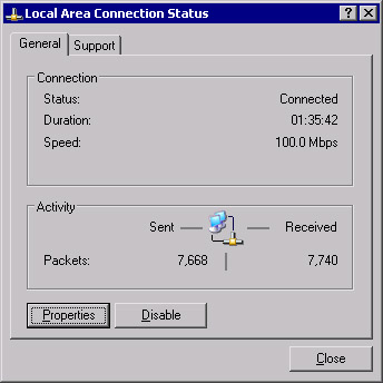
Figure 3.11: Local Area Connection Status -
Click Properties.
-
In the Local Area Network Connection Properties dialog box, shown in Figure 3.12, click Install.
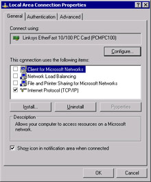
Figure 3.12: Local Area Connection Properties -
In the Select Network Component Type dialog box, select Protocol, as shown in Figure 3.13, and click Add.
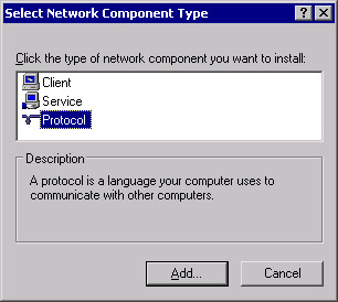
Figure 3.13: Select Network Component Type -
In the Select Network Protocol dialog box, select Microsoft TCP/IP version 6, as shown in Figure 3.14, and click OK.
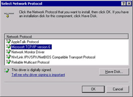
Figure 3.14: Select Network Protocol -
You should return to the Local Area Connection Properties dialog box and see that Microsoft TCP/IP version 6 is installed, as shown in Figure 3.15.
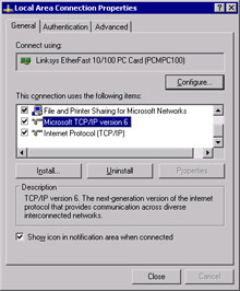
Figure 3.15: Local Area Connection Properties with TCP/IP Version 6 Installed -
Click Close.
-
Test the TCP/IP version 6 installation by opening Internet Explorer and navigating to www.ipv6.org. You should see a line under the line “Welcome to the IPv6 Information Page!” that states, “You are using IPv6 from <your IPv6 address>,” as shown in Figure 3.16. If you are behind a firewall or using 6to4 tunneling, you may not see the message that indicates you have an IPv6 address. If you are able to access the site described in step 9, then you are successfully using IPv6.
Note You might need to reboot after installing IPv6.
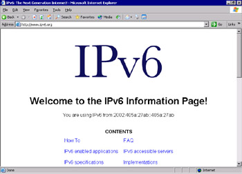
Figure 3.16: Test the IPv6 Configuration -
You can also navigate to an IPv6-only site from Microsoft Research. In Internet Explorer, navigate to http://ipv6.research.microsoft.com, as shown in Figure 3.17.
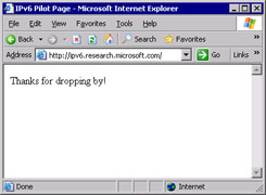
Figure 3.17: IPv6 Pilot Page at Microsoft Research
| Note | You will not be able to browse IPv6-only Web sites with Microsoft Internet Explorer if you use a proxy server (unless the proxy server is IPv6-enabled). |
Another way to test whether your IPv6 installation was successful is to run the ipconfig command. If IPv6 is installed, your IP address will be shown in IPv6 format, as shown in Figure 3.18.
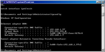
Figure 3.18: ipconfig Results after Installing IPv6
Now that TCP/IP version 6 is installed, additional utilities are available with the IPv6 functionality. Other than the utilities to manage, monitor, and troubleshoot IPv6, only Telnet, FTP, and Internet Explorer actually use the IPv6 protocol stack.
netsh Commands
netsh is an interactive command-line utility that allows you to manage local or remote network configurations of active machines. netsh also supports scripting, so you can create batch configurations that run against the local machine or a specified host on the network. You can also use the Netsh utility to generate a configuration script to use as a backup configuration or as an aid to configure new machines in an identical fashion.
netsh works with the existing components installed with the operating system by using helper dynamic link libraries (DLLs). Each helper DLL contains the information necessary to execute the commands for the component to which it applies. The set of commands and features supported by the DLLs is called a context, and each context is unique to the networking component.
The IPv6 interface has its own context with commands to manage and display information pertaining to the routes, interfaces, addresses, and caches specific to IPv6. There are currently no graphical user interface (GUI) applications to configure IPv6, so netsh is necessary for configuring IPv6 and its associated components. The component called 6to4 has a subcontext within the IPv6 context, for configuring and managing 6to4 routers and hosts. For more information about Netsh, see the Windows Help and Support Center topic titled “Netsh Overview.”
To put the netsh command into IPv6 context, type netsh at the command prompt, then at the netsh> prompt, type interface ipv6. Then you can use the IPv6 context commands, which include the following:
-
6to4 Changes to 6to4 context.
-
Add Adds a configuration entry.
-
Delete Deletes a configuration entry.
-
Dump Shows a configuration script.
-
Install Installs IPv6.
-
Isatap Changes to isatap subcontext within IPv6 context.
-
Renew Restarts IPv6 interfaces.
-
Reset Resets IPv6 configuration.
-
Set Sets configuration information.
-
Show Displays information.
-
Uninstall Uninstalls IPv6.
Ipsec6.exe
Ipsec6.exe is used to configure and implement IPSec security policies (SPs) and security associations (SAs) for IPv6. Using this utility, you can save and load security policies and security associations to a file that can be edited in a text editor. This can be a real timesaver when you implement IPSec for IPv6 on multiple machines. The command to save a configuration is ipsec6 s FilenameWithNoExtension. The filename specified from the command line will be appended with the extension automatically. The extension .spd is added to security policy files, and the extension .sad is added to security association files. If you are executing this command for the first time, and there are no current policies and no current security associations, the files created can act as templates to help you get started.
Other ipsec6 commands are available to works with security policies and security associations:
-
To load the configuration from these files, type ipsec6 l FilenameWithNoExtension. The security policies will be loaded from Filename.spd and the security associations from Filename.sad.
-
To delete security policies and security associations, type ipsec6 d [{sp | sa}] [Index] from a command line. Use the sp parameter with the Index of the policy you wish to delete, or the sa parameter to delete all of the security associations.
-
To determine what the current security policies are, type ipsec6 sp [Interface] from the command line, where Interface is optional and applies to the security policies for the specified network interface.
-
To view the current security associations, type ipsec6 sa from the command line. Note that the output from the commands to view the security policies and security associations is not formatted well for a command line, so you might prefer to save the configuration and view the files in Notepad.
Test Day Tip According to Microsoft Help and Support Center documentation, the current version of IPSec for IPv6 is not recommended for use in a production environment, so you should not be concerned about anything more than being familiar with it for the exam.
IPv6 PING and Tracert Parameters
Use the following steps to use IPv6 PING to verify connectivity:
-
From a command prompt, type netsh interface ipv6 show interface.
-
Find the Idx value for Local Area Connection.
-
Type netsh interface ipv6 show interface Idx, where Idx is the number from the previous step. The Local Area Connection index number is usually 4.
-
Right-click in the command window and select Mark. Then highlight the address. Once it is highlighted, right-click in the command prompt window. When you release the mouse button, the address will be copied to the Clipboard. Take note of your Zone ID for Link, which should match the Idx number in step 3.
-
Exit the netsh command. At a regular command prompt, type ping, and then right-click in the command prompt window and select Paste.
-
Without adding any spaces, add %<ZoneID>, where ZoneID is the number noted in step 4, so the command looks like this:
Ping fe80::204:5aff:fe08:fb4b%4
-
Press Enter. You should see four successful replies.
-
Continue by pinging another address on the same local network.
-
To test external hosts, ping the global address of another node.
-
To test name resolution with DNS or a hosts file, ping a node with ping -6 Name, where Name is the site name. The -6 parameter tells PING to use IPv6 only.
You can use Tracert to trace the path taken by IPv6 data packets from this host to the destination host. From a command prompt, type tracert IPv6Address%ZoneID, where IPv6 is a valid IPv6 address and ZoneID is the destination address. Alternatively, type tracert –d -6 Hostname, where Hostname is the name of the remote machine.
| Note | Windows XP Professional includes three utilities not included with Windows Server 2003: ipv6.exe, ping6.exe, and tracert6.exe. |
6to4 Tunneling
6to4 tunneling is used to encapsulate IPv6 data packets in IPv4 headers before they are transmitted to the destination host. 6to4 tunneling uses a 6to4 host and 6to4 routers to deliver the IPv6 data. It is an Internet standard, defined in RFC 3056, and is used for interoperability between IPv4 and IPv6 networks. 6to4 hosts and routers are defined as follows:
-
6to4 host Any IPv6 host that is configured with at least one 6to4 address. 6to4 can be configured with the netsh interface ipv6 6to4 commands. As you might have noticed when you ran the show interface command, by default, your IPv6-enabled host will have a 6to4 pseudo-interface, as well as an automatic tunneling pseudo-interface.
-
6to4 router Uses IPv4 and IPv6 to forward 6to4 traffic to the destination 6to4 hosts. It is also possible to implement a 6to4 relay router to forward 6to4 router traffic on the IPv6 Internet.
With 6to4 tunneling, it is not necessary for IPv6 hosts (such as the computer on which you installed IPv6 in Exercise 3.4) to get an IPv6 global address prefix from their ISPs. The host can create a 6to4 address automatically.
IPv6 Helper Service
The IPv6 Helper service is responsible for automatically configuring itself with the appropriate 6to4 addresses, but it uses a specific 6to4 router on the Internet. You can test functionality with the ping -6 command.
The 6bone
The 6bone is a dedicated IPv6 network that exists on the Internet. It began as a virtual network using IPv6 over IPv4 encapsulation. It contains links to many sites and includes a great deal of IPv6 data, testing plans, news, current events, and implementation instructions. It will be a valuable resource for managing IPv6 on your network. For more information about the 6bone, see www.6bone.net. For instructions on how to connect to the 6bone, see www.opus1.com/ipv6/whatisthe6bone.html.
Teredo (IPv6 with NAT)
Teredo is the name for IPv4 network address translator (NAT) traversal for IPv6. It provides an IPv6/IPv4 translation over NAT and address assignment. Teredo also provides the mechanism for host-to-host automatic tunneling for unicast IPv6 connectivity when IPv6/IPv4 hosts are located behind one or more NAT servers.
Currently, to provide IPv6 connectivity over the Internet, you must have a 6to4 router with a public IPv4 address, which is not always feasible. Teredo provides a mechanism for IPv6 traffic to traverse NAT and access the Internet using IPv6. Basically, IPv6 packets are sent as IPv4-based UDP messages, and this allows the IPv6 packets to pass through the IPv4 NAT server. For more information about Teredo, see the Teredo Overview document located at www.microsoft.com/windowsxp/pro/techinfo/administration/p2p/overview.asp.
|
EAN: 2147483647
Pages: 173