Understanding Windows Server 2003 Network Protocols
|
EXAM 70-293 OBJECTIVE 2, 2.1.2
In order for computers to communicate with other computers and hardware resources, they must use a common messaging structure, much like a language used to speak to other network devices. There are many message structures that are standardized and designed to provide reliable, continuous, high-speed data transfer and remain independent of the device or computer’s hardware and operating system. When planning a network, you need to understand how the computers will share and access information and resources on the network so that you can decide which network protocol is best suited for the task.
The networking architecture of Windows Server 2003 uses the Network Driver Interface Specification (NDIS). NDIS provides a kind of wrapper in the I/O Manager layer of Windows that allows the hardware driver to be independent of the protocols used to communicate on your network. Additionally, this allows for multiple network adapters with virtually any device driver, without having any effect on the transport protocols used. Let’s take a look at some of the details involved with networking.
Identifying Protocols to Be Used
EXAM 70-293 OBJECTIVE 2.2.2
Network protocols are composed of software components designed specifically for communication with other networked machines. A variety of protocols are used for different functions. In order to be able to select protocols for particular tasks, it is important to understand how protocols facilitate network communication.
The first concept to understand is the standard model for network communications, known as the Open Systems Interconnection (OSI) reference model. The International Organization for Standardization (ISO) developed the OSI reference model. One of this organization’s responsibilities is to provide a standard by which computers can communicate worldwide, and the OSI reference model was designed to accomplish this goal.
The OSI model is based on a concept of a stack of protocols that work together to provide the means for transmitting data. The OSI model is composed of seven layers of protocols responsible for different tasks related to data transmission. Each layer of the OSI model describes a function:
-
Application layer Defines how applications work together over the network.
-
Presentation layer Provides a common data format for the data transmitted.
-
Session layer Coordinates the establishment of the connection and maintains the open connection.
-
Transport layer Provides the mechanism for ensuring error-free delivery of data.
-
Network layer Provides the addressing for messages for all networks.
-
Data Link layer Defines the methods for the software drivers to access the hardware that is the physical medium, such as the network jack and the cable that plugs into it.
-
Physical layer Puts the data on the physical medium that is carrying the data.
The data that you transmit is broken up in manageable chunks called packets, which will be transmitted as a single unit via the OSI layers. As the packet is passed down through each layer, information is added to aid the delivery of the packet to the corresponding layers on the destination machine. The protocols that work together to provide the packaging, delivery and receipt of the data at each of these layers are known collectively as a protocol stack.
The size of your network and the topology—how it is physically laid out—have a bearing on which protocol stack will be suitable for your needs. If you have a large network, the volume of traffic may need to be managed. One of the most common solutions to traffic problems is to break up the network into smaller, more manageable networks known as segments. In order for you to combine these smaller networks together, the data must be able to travel from one network to the other along one or more physical paths. This transmission of data across network segments is called routing. In this situation, you would need to select a protocol stack that provides routable protocols. The two most common routable protocols are TCP/IP and Internetwork Packet Exchange/Sequenced Packet Exchange (IPX/SPX).
Some protocol stacks are composed of nonroutable transport protocols such as NetBIOS Extended User Interface (NetBEUI). These protocol stacks are simple to configure and implement, but they are suitable only for small networks that are not segmented. Nonroutable protocols limit your capabilities to expand your network. Your network might be required to interact with another existing network. In that case, the ability of protocols in the stack to route traffic becomes an issue.
There are other factors to consider when deciding which protocol to use. One consideration is reliability. Is it necessary to ensure the transmission of data? Some protocols just broadcast data and don’t ensure that the data is received by the targeted machine. You should also consider the number of machines you have on your network. If you have a lot of devices, you may need to consider a more scalable, enterprise-capable protocol suite that includes transport protocols that provide guaranteed delivery and data integrity.
Another issue is the security of the data. You may have applications that transmit sensitive data over the network. You would not want anyone to be able to monitor that traffic and view the data. This would lead to selecting a protocol stack that provides protocols that allow you to encrypt the data and potentially validate the source and authenticity of the data. An example of this would be Internet Protocol Security (IPSec).
You may need to provide network services to the clients. These network services should be easy for the clients to access. In addition, the network services may provide a variety of functions, including data access, license services, printing services, and remote-access services over modem dial-up. Network services may also provide special communication features related to the medium, such as Infrared Data Association (IrDA), Asynchronous Transfer Mode (ATM), and other features that are used to remotely access networks using existing network connections called virtual private networks (VPNs). In order to leverage these services, the protocol stack should provide protocols that support the required features. For instance, VPNs use Point-to-Point Tunneling (PPTP) or Layer Two Tunneling Protocol (L2TP) to establish connections, both of which require TCP/IP to connect over the Internet. Once connected, PPTP and L2TP provide a channel to encapsulate and transmit other protocols such TCP/IP, IPX/SPX, and NetBEUI as if you were on the same physical segment as other machines on the physical local area network (LAN).
Additionally, accessing the Internet is rapidly becoming a necessity for most businesses today. In order to access the Internet, you must have TCP/IP. You may provide other means to transmit data on your network, but Internet resources support only the TCP/IP protocol stack.
On the Windows Server 2003 platform, there are two basic choices of protocol stacks: TCP/IP and IPX/SPX. There are other protocol stacks; however, TCP/IP and IPX/SPX are the most prevalent, and they support such a robust suite of protocols that it is not usually necessary to use any others.
Considerations for Selecting Appropriate Network Protocols
There are many factors to consider when you decide which protocol or protocols to implement on your network:
-
Security Do you transmit sensitive data between machines?
-
Reliability Will you use applications that ensure delivery and integrity of the data you transmit?
-
Ease of implementation and maintenance What is the total cost of ownership (TCO) to implement and maintain the selected protocols? Consider the cost of equipment, training, management, implementation, and future growth of the organization.
-
Traffic Routable network protocols allow for better management of traffic and isolate broadcast traffic, which, in turn, reduces the amount of unnecessary data that must be handled by the network hardware.
-
Number of devices How many machines will communicate on your network segments? Too many machines on one segment could overload your network and cause slower and more unreliable data transfer. How scalable is the protocol? Does it work well on a small network and does it allow for growth?
-
Physical topology Are you implementing or integrating with a LAN, metropolitan area network (MAN), or wide area network (WAN)? What protocols are you currently using? Where are the machines physically located in relation to other machines on your network?
-
Function Will you need to provide access to the Internet for users or systems on your network? Do you want to prevent access to the Internet? Will there be an intranet? Will you need to provide a stream of data to multiple destinations?
-
Existing protocols Do you have a requirement to access resources on your network using existing protocols?
Advantages of the TCP/IP Protocol Suite
The TCP/IP protocol suite has many advantages over other protocol suites like IPX/SPX and NetBEUI. These advantages are due to TCP/IP’s robust, stable, extensive feature set, combined with its scalability. The suite of protocols and services that are part of the TCP/IP standards provide valuable and prevalent services, so it is no wonder that it is the default protocol for virtually every client and network operating system in use today!
One of TCP/IP’s key advantages is that it is an open, industry-standard set of protocols, which implies that there is not one single organization that controls the standards. Novell provides IPX/SPX, which makes it a vendor-specific protocol. This implies that it was developed specifically to support NetWare’s architecture and may not be as robust, or even supported, on other platforms.
TCP/IP contains applications that aid in connecting different operating systems, which ensures that you will be able to communicate in prescribed methods with any system that is using TCP/IP. The architecture of TCP/IP provides scalability—the means for sizing the network so that you can expand or shrink the network as your needs change.
Another advantage of TCP/IP is that it is routable. Routable protocols can reduce network traffic by isolating logical and physical networks. Isolating the networks allows you to better manage network traffic, direct transmissions, and restrict the distribution of broadcast traffic. You can also leverage the information about the routes from one point to another to troubleshoot and isolate problems with connections. You can use dynamic routing features to reroute traffic to prevent interruption of communications. The U.S. Department of Defense Advanced Research Projects Agency (DARPA) intended for TCP/IP WANs to provide a means for ensuring reliable communications in the event that portions of the network become unavailable. Routable protocols provide forms of addressing, such as an IP address, that define mechanisms for determining how to transmit data across network segments.
Nonroutable protocols do not use addressing, so there must be a means for determining the destination for data transmitted. An example is NetBIOS naming, which provides the architecture for defining the destination resource and the methods for sending the data to one or multiple destinations. NetBIOS naming provides for two types of names: a unique name and a group name. The unique name defines the station on a network, enabling you to connect to and communicate with the server. Group names are used to provide a means to send messages to multiple machines at once, but only those machines that are part of that group will listen to the messages.
TCP/IP was designed to be platform-independent. This allows you to connect and integrate different operating system platforms and hardware, and they will be able to communicate effectively, regardless of the platform. In addition, the suite of protocols includes methods for accessing data and resources on the various platforms, such as Line Printer Daemon (LPD) for printing, File Transfer Protocol (FTP) for file exchange, and Hypertext Transfer Protocol (HTTP) for sharing platform-independent documents, images, and other media.
The Internet and the World Wide Web are accessible only via TCP/IP. There is a vast amount of educational, research, and entertainment resources available to the world on the Internet. It is also possible to use the Internet to interconnect networks around the world. You can log on a network in London from an office in Dallas and function as if you were in the London office. You can imagine how scalable the protocol is if it can service both a small office and the whole world.
Microsoft adds the ability to develop applications that leverage these advantages by providing the Windows Sockets API (WinSock). WinSock makes it possible for developers to design scalable TCP/IP client/server applications that can interoperate with any machines that use TCP/IP on any operating system platform. Since virtually every modern operating system uses TCP/IP, this makes WinSock a very viable framework.
| Exam Warning | There are many different protocols that make up the Microsoft TCP/IP protocol suite. Don’t forget that it is a suite of protocols, which includes many different features that all leverage the TCP/IP protocol stack. The Microsoft TCP/IP protocol suite provides applications and protocol functions that are designed specifically for Windows enterprise networking and the Windows operating system platform. The TCP/IP protocol stack is the industry-standard, platform-independent set of protocols that work at various layers to communicate over networks. |
The Multiprotocol Network Environment
Microsoft Windows Server 2003, like its predecessors, uses a layered network architecture. Since it is layered, it makes it possible to extend the functionality of networking Windows Server 2003 with third-party software components. The layered structure also provides the Windows Server 2003 platform with the ability to allow different protocols to communicate using the same structure and methods, so users can access data in the same fashion, regardless of what networking protocol is used.
For instance, it is possible for a Novell NetWare server using the IPX/SPX network protocol stack to be accessible to a Windows Server 2003 machine using IPX/SPX. You can also use Windows Explorer on the Windows Server 2003 computer to access files on the NetWare file server without requiring any special features. If you need to run Novell Directory Services (NDS) utilities on Windows, you must also install the NetWare Client Software, which uses the IPX/SPX protocol to access those services. This type of multiprotocol configuration makes integration of other systems possible using third-party software.
Windows Server 2003 products use the TCP/IP protocol stack by default. The following network protocols are supported on Windows Server 2003:
-
TCP/IP version 4 The default protocol for Windows Server 2003.
-
TCP/IP version 6 The next generation of TCP/IP.
-
IPX/SPX Used by many networks running Novell NetWare.
-
AppleTalk Provides the basis for Services for Macintosh and AppleTalk routing and seed routing support.
The Windows Server 2003 architecture that supports multiple protocols also allows multiple network adapters. Each adapter can use any combination of protocols or networking components, known as binding. It is also possible for you to change the order in which protocols are bound to the adapter. You can choose to move the most commonly used protocols on the client up to the top of the binding order to provide faster performance. For example, your LAN may access NetWare services using IPX/SPX and Windows networking services using TCP/IP. In this example, let’s assume that the NetWare services are not used very often, so your primary network communications use TCP/IP. You can change the protocol binding order as follows:
-
Select Start | Control Panel | Network Connections.
-
From the menu bar, select Advanced | Advanced Settings.
-
On the Adapters and Bindings tab, move the primary connection (if there is more than one) to the top of the list.
-
Select a connection, and the bindings will be displayed for that adapter.
-
Under File and Printer Sharing for Microsoft Networks, select Internet Protocol (TCP/IP) and move it up to the top of the list using the arrows in the dialog box.
-
Under Client for Microsoft Networks, select Internet Protocol (TCP/IP) and move it up to the top of the list using the arrows in the dialog box.
-
On the Provider Order tab, move Microsoft Windows Network to the top of the Network Providers list.
-
Click OK.
Test Day Tip Understand how to add different adapters, protocols, services, and clients. You should be able to differentiate between a client as a service and a protocol, as well as how to change the bindings and their order for each.
Using multiple protocols on your network might provide a degree of flexibility, but it can also make your job more difficult. If you use a protocol that generates a lot of unnecessary broadcast traffic, it could harm your overall network performance. From the client’s perspective, network problems could be more challenging, because each protocol bound to the adapter will be attempted in the event that some network connections are unavailable.
When configuring protocols on your computer, it is always desirable to make the fewest possible changes on the client in order to simplify the administration of the network. On a TCP/IP network with more than 25 hosts, it is a good idea to implement a DHCP server. A DHCP server will allow you to define certain settings related to host name resolution and topology, and automatically provide the proper address for the hosts that are configured to use DHCP. By default, all Windows XP and Windows Server 2003 machines are configured to use DHCP.
Windows Server 2003 Networking Features
Windows 2003 Server products offer several networking features and protocols. There have been several changes to the protocols and services available. While some of the support for older protocols is no longer available, new support is available for the latest technologies. The following are some of the changes made to networking features:
-
Wireless networking functionality supports the 802.11 standard and reduces the hassles associated with configuring wireless networking.
-
802.1x authentication is enabled by default. This enables tighter wireless security than is possible with Wired Equivalent Privacy (WEP) encrypted connections. 802.1x authentication also supports Extensible Authentication Protocol (EAP), which allows third-party security enhancements like smart cards and certificates.
-
The NetBEUI and Data Link Control (DLC) protocols are no longer available on any Windows Server 2003 products.
-
The 64-bit versions of Windows Server 2003 products do not include IPX/SPX or any of the IPX-related services, nor the routing protocol, Open Shortest Path First (OSPF).
-
The infrared (IR) networking feature is supported only on Windows Server 2003 Standard Edition.
-
Gateway Services for NetWare (GSNW) is not included in Windows Server 2003 products.
-
Windows Server 2003 products cannot act as IPX routers.
-
It is not possible to uninstall the TCP/IP protocol on Windows Server 2003. Since you cannot uninstall and reinstall, there is a new netsh command that is used to reset the TCP/IP stack. To use this command, from the command line, type netsh ip interface reset.
Occasionally, you might need to manually configure the IP address of your machine. The following are some servers or services that may require a static (manually configured) IP address:
-
A DHCP server
-
Windows Routing and Remote Access Services (RRAS)
-
Domain Name System (DNS) and Windows Internet Name Service (WINS) servers
-
Any other service that provides IP functionality on your servers
If you do configure the address manually, pay close attention to the information you provide in the dialog box. Errors in the configuration will hinder network communication for that machine, and in some cases, cause problems that could prevent other machines from functioning properly.
Exercise 3.01: Configuring the TCP/IP Protocol Manually
In the following exercise, you will learn how to configure an IP address manually on a Windows Server 2003 computer.
-
Open the Local Area Connection Status dialog box by clicking Start | Control Panel | Network Connections and double-clicking the appropriate local area connection. You will see the dialog box shown in Figure 3.1.
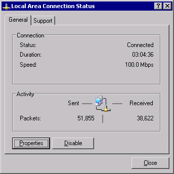
Figure 3.1: Local Area Connection Status -
Click Properties to open the Local Area Connection Properties dialog box, shown in Figure 3.2.
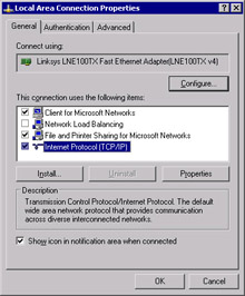
Figure 3.2: Local Area Connection Properties -
Click Internet Protocol (TCP/IP), and then click Properties to open the Internet Protocol (TCP/IP) Properties dialog box, shown in Figure 3.3.
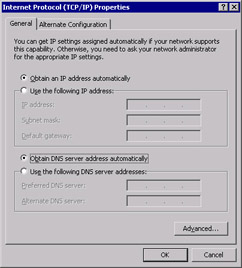
Figure 3.3: Internet Protocol (TCP/IP) Properties -
Click the Use the following IP address radio button and provide the IP address, Subnet mask, and Default gateway, as shown in Figure 3.4.
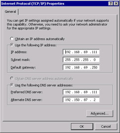
Figure 3.4: Internet Protocol (TCP/IP) Properties after Manual Configuration -
Click the Use the following DNS server addresses radio button in the Internet Protocol (TCP/IP) Properties dialog box and provide at least one DNS server IP address (see Figure 3.4).
-
Click Advanced to open the Advanced TCP/IP Settings dialog box, as shown in Figure 3.5.
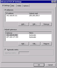
Figure 3.5: Advanced TCP/IP Settings -
Notice the new Automatic metric option. Note that it is the default for all Default gateways.
-
Click OK.
Internet Control Message Protocol (ICMP) Router Discovery
ICMP is a maintenance protocol that is part of the IP layer in the Microsoft TCP/IP stack. Its functions include providing diagnostics, leveraging the use of the PING utility, and managing flow control of data to prevent traffic from saturating network links or routers. It also provides the facility that builds and maintains the routing tables, as well as determines the size of the packets that will be sent to a destination.
RRAS on Windows Server 2003 supports a new feature called ICMP router discovery. ICMP router discovery uses ICMP messages to “discover” the routers on the current subnet and select one to act as the default gateway. This allows DHCP clients to find a default gateway when one is not specified by the DHCP server.
This feature is disabled by default on Windows Server 2003 and Windows XP machines. In order to enable a DHCP client to perform router discovery, the client must receive a “perform router discovery” option from a DHCP server. This will enable the host to broadcast the request to all available routers. You must also set the option to Enable router discovery announcements on the General tab of the Windows Server 2003 RRAS Properties dialog box in order for the router to send the router advertisements.
To view your current IP configuration, you can run ipconfig from the command line. For more detailed information, use ipconfig /all. If you want to release your DHCP-assigned IP addresses from all adapters, use ipconfig /release. You can obtain a new lease with ipconfig /renew. For the release and renew commands, you can also specify the name of a specific adapter.
Reviewing TCP/IP Basics
TCP/IP on Windows Server 2003 provides a scalable, robust client/server platform that is built on industry-standard, routable, and full-featured protocols. Virtually every network operating system supports the TCP/IP protocol stack, and this allows Windows Server 2003 to integrate dissimilar systems on the network. The various protocols that make up the TCP/IP stack work together to provide network communications. These network communications provide the architecture that the Windows Server 2003 TCP/IP suite uses to leverage services such name resolution, file transfers, and Internet access.
Every implementation of TCP/IP must follow the guidelines that are governed and managed by several agencies such as the Internet Architecture Board (IAB) and the Internet Engineering Task Force (IETF). The IAB is also responsible for managing several other groups, such as the Internet Society (ISOC), Internet Assigned Numbers Authority (IANA), and Internet Corporation for Assigned Names and Numbers (ICANN). These agencies work together to maintain an open standard using a process known as Request for Comments (RFCs) and provide the maintenance, distribution, and administrative handling of the RFCs. For information on RFCs, access the IETF Web site at www.ietf.org.
Virtually all network protocols can be mapped to the ISO’s OSI reference model. The OSI model is intended to provide a general direction for developers for designing network drivers and protocols. The design intends for different components involved with network communication to be managed in a series of layers, with each layer built on top of another, having a specific set of functionality, and communicating with the adjacent layers. The layers allow for a hardware manufacturer to design a network card without regard to the operating system or applications that will be using the network card to communicate. A developer can design a client/server network application without concern for the protocols used to communicate with other machines.
| Exam Warning | ISO is the organization that defines the standards for the OSI model. The IAB is responsible for facilitating the rules and the processes for the standards that define the Internet. The standards for the Internet are maintained by the IETF and are called RFCs. |
TCP/IP uses a slightly less complex networking model that was developed by DARPA. Since the model is less complex than the OSI model, it is easier to implement and has better performance characteristics. The DARPA model and the TCP/IP suite of protocols were designed by DARPA before the development of the OSI model. The Windows implementation of the TCP/IP protocol stack relates to the seven layers of the OSI model.
The layers in the TCP/IP model span several layers of the OSI model. As shown in Figure 3.6, the Application, Presentation, and Session layers of the OSI model are incorporated into the Application layer of the TCP/IP model. Some of the components of the TCP/IP protocol suite that operate in this layer are FTP, Telnet, HTTP, and DNS. The Application layer provides the access to the network for many applications, such as Microsoft Internet Explorer. At this layer, presentation issues such as compression and encryption are handled, and sessions are established (if applicable). Then the sending computer passes the data down to next layer, the Transport layer.
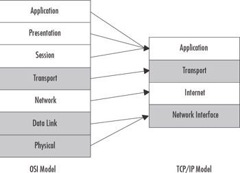
Figure 3.6: OSI Model versus TCP/IP model
The Transport layer coordinates the applications’ communication sessions with other interconnected machines. The key protocols that operate at this layer are TCP and User Datagram Protocol (UDP). TCP differs from UDP in two key ways. The first distinguishing difference is that TCP is connection-oriented and UDP is connectionless. TCP expects acknowledgment from the other host for each packet of data transmitted. This is ideal for large data transfers over very large networks. FTP uses TCP ports 20 and 21 to transfer data. Because UDP is connectionless, it doesn’t guarantee the delivery of the data; it just makes its best effort to deliver the packets intact. This type of data transfer is ideal for lightweight, small data transfers on a well-connected network. Trivial File Transfer Protocol (TFTP) uses UDP port 69 to initiate a connection, and the server will then dynamically select a port number to return data from. Then the two machines continue to communicate using the new port numbers. Since TFTP uses UDP, it is well-suited for small files, such as short text files, and is faster than using FTP over TCP, since there is less overhead.
| Test Day Tip | UDP and TCP both use the IP protocol. TCP is directed to the destination and ensures the delivery of packets by receiving acknowledgments of data delivery. UDP attempts a best-effort delivery of the datagram and does not guarantee delivery. UDP has less overhead, so it is much faster, but it is not as reliable as TCP. Both TCP and UDP use ports to differentiate between communications to and from different applications. |
On a sending computer, the Transport layer passes the data down to the Internet layer. The Internet layer, which maps to the OSI model’s Network layer, is responsible for addressing and routing communications over the network. IP operates here, and it is responsible for determining whether the address of the destination computer is on the same subnet as the address of the sending computer. In order to physically locate another host on the network, Address Resolution Protocol (ARP) is used for IP address-to-Media Access Control (MAC) address resolution. Other protocols that operate at this layer are ICMP, IGMP, and IPSec. The Internet layer continues the communication process by passing data to the Network Interface layer.
| Exam Warning | ICMP provides diagnostics and error reporting. The PING utility uses ICMP to send and receive a standard packet to determine if the data delivery was timely and successful. ARP determines the physical address, or MAC address, of the destination host. IP determines whether the address is local or remote. If the address is local, it will direct ARP either to refer to its local cache or broadcast on the local subnet to resolve the MAC address. If it is determined by IP that the address is not local, ARP will resolve the MAC address of the default gateway to allow the traffic to be routed to the appropriate network. If you are using Internet Connection Firewall (ICF) or any other firewall software, you may prevent PING from functioning if you have defined any settings or filters that block ICMP traffic. By default, ICMP traffic is disabled when you enable ICF. |
The last layer (when data is being sent) is the Network Interface layer. This layer maps to the Physical and Data Link layers of the OSI model. It is responsible for the software driver-to-hardware translation and complying with the hardware communication standards such as Ethernet, ATM, and Token Ring. The Network Interface layer is isolated from the hardware on Windows 2003 Servers by NDIS, which is a boundary layer implemented in the Microsoft networking model. This allows the protocols to function independently of the network hardware. The MAC address is part of this layer.
The Microsoft networking model corresponds to different services in the Windows architecture, to provide similar ways to access data independently of the mechanism. For instance, using Windows Explorer to access files using IPX/SPX does not seem any different to the user than accessing files using TCP/IP. Network-aware applications and network service providers operate as User mode services at the Application layer and the top of the Presentation layer.
The Presentation layer transitions data back and forth from User mode to Kernel mode. The Executive services provide Session support and transition data to the I/O Manager. The Server and Redirector (Workstation) services operate at the Session layer and are separated from the transport protocols by the Transport Driver Interface (TDI) boundary layer, which traverses the Session and Transport layers.
The transport protocols, such as TCP/IP and IPX/SPX, transition from the Transport layer, over the Network layer and down to the Network Interface or Data Link layer. The Data Link layer is where NDIS accesses the network adapter drivers before passing the data to the Physical layer, which allows the different protocols to be bound to different network adapters, using different physical connections.
Figure 3.7 illustrates the TCP/IP protocol suite in the TCP/IP model.
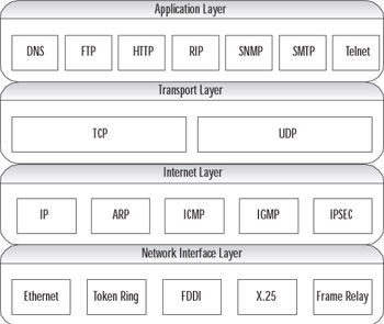
Figure 3.7: TCP/IP Protocol Suite and the TCP/IP Network Model
| Note | Although we started “at the top” in describing the layers of the TCP/IP (DoD) model, it is important to remember that when they are numbered, they are referred to in reverse order (as in the OSI model). The Network Interface layer is layer 1, the Internetwork layer is layer 2, and so forth. |
Each layer in the protocol stack provides a translation or some form of communication with the next layer. As data is passed down through the stack, each layer adds its necessary headers and protocol-specific data, and encapsulates the data from the previous layer. In some instances, the layer will establish a session with the destination host at the same layer. Once the data reaches the destination, each layer in the protocol stack will validate the header that was added by its corresponding layer, and then strip the protocol-specific information from the packet and pass it up to the next layer until it reaches the destination application.
What’s New in TCP/IP for Windows Server 2003
There are many enhancements to the networking and communications components of Windows Server 2003. The TCP/IP protocol suite has been enhanced with some of the latest technologies, as well as improvements on existing functionality. For more information about other networking and communication feature enhancements, see the white paper titled “Microsoft Windows Server 2003- Technical Overview of Networking and Communication” (www.microsoft.com/windowsserver
2003/techinfo/overview/netcomm.mspx).
IGMPv3
Typical communications over an IP-based network are directed unicast communications. Unicast is basically a single, direct request sent from one host to another, and only the two hosts interact over the established route. For example, when you click a hyperlink in a Web browser, you are requesting HTTP data from the host defined in the link, which, in turn, delivers the data to your browser. This is useful in the Web-browsing environments we have grown accustomed to, where there is a demand for a personal, user-controlled experience.
Unicast is not useful for delivering streams of audio or video to large audiences, since a single stream of audio/video data is very costly for only one user. This is where multicast communications are effective. Multicast provides a single stream for multiple hosts. The hosts select the data by requesting the local routers to forward those packets of data from the host providing the multicast data to the subnet of the listening host. When the host decides to stop listening to the multicast traffic, IGMP is responsible for notifying the router that the host is no longer participating.
| Test Day Tip | It is not necessary to know the differences between different versions of IGMP. It is important to be familiar with the purpose of IGMP, what its functions are, and where it fits in the OSI model. |
A set of listening hosts is called a multicast group. IGMP is responsible for providing the functionality necessary for hosts to join and leave those groups that receive IP multicast traffic. Each of the versions of IGMP—versions 1, 2, and 3—is automatically supported by Windows Server 2003. IGMPv3 adds functionality to distribute multiple multicast sources regionally and allow the host to select the multicast source that is located closest to the host.
An example of this would be a situation in which you send a video stream broadcasting a speech from the president of your company and have several machines scattered across the United States providing the feed. Then IGMPv3 allows the hosts to provide an include list or an exclude list of those servers. The multicast routers would be responsible for forwarding the multicast traffic from the include list of servers and for preventing the forwarding of traffic from the excluded sources. As you can see, this feature can be very useful to help reduce network bandwidth utilization.
IPv6
The next generation of TCP/IP is here! Previously, it was possible to experiment with IPv6, but under the covers, the protocol stack was still dependent on IPv4 calls for WinSock functions. With the release of Windows Server 2003, the IPv6 protocol stack is designed for production use.
IPv4 has a limited number of host addresses available (232, or about 4 billion hosts). That might sound like a lot, but over the past 30 years, the pool of available addresses has been exhausted due to the popularity and growth of the Internet. With IPv6, the host address is 128 bits instead of 32, which means that we will have 2128 (about 340,000,000,000,000,000,000,000,000,000,000,000,000) host addresses available. That means we could have about 296 (about 75 trillion trillion, or 75,000,000,000,000, 000,000,000,000,000) addresses of our very own. That should last for at least a couple of years. We will discuss transitioning to IPv6 and its features in more detail in the “Transitioning to IPv6” section later in this chapter.
Alternate Configuration
Automatic alternate configuration is an enhancement to TCP/IP that allows for a valid static IP address configuration on a DHCP-configured machine. Without an alternate configuration defined, a computer that is unable to obtain an IP address lease from a DHCP server will automatically receive an Automatic Private IP Addressing (APIPA) address from the 169.254.0.0/16 pool.
Using APIPA to Your Advantage
APIPA can be a valuable aid in assisting you with network configuration. With no effort at all, you can provide IP addressing for a TCP/IP network of Windows Server 2003 and Windows 98/2000/XP computers. APIPA is service that uses a reserved class B IP address pool (169.254.0.0/16 or a subnet mask of 255.255.0.0) to automatically provide valid IP addresses to DHCP clients in the event the computer cannot obtain a DHCP lease. This scheme is intended for smaller networks where there is no DHCP server deployed, but think of the potential use this has, not only as a way to assist your LAN users, but also to help you troubleshoot network problems and configure new servers.
One way you can help LAN users is to provide an intranet Web server that has been assigned an APIPA address. That way, if a client is unable to obtain an IP address, the user will be able to connect to this Web server. The Web server’s default home page should contain a series of simple troubleshooting procedures that the client could use, such as the following:
-
Did you receive an error message on startup? Provide a list of common errors and probable solutions.
-
Wait 5 minutes to see if the next DCHP request is acknowledged.
-
Contact technical support at extension 5555.
Additionally, you could provide users with some basic information about what is happening or maintain a server status page to let them know that you are aware of the problem and what actions they should take. It might also be beneficial to the Information Technology (IT) staff to maintain documentation on the Web server to aid in configuring new servers, maintaining static address pools, or initiating service requests to add new equipment to the network.
Automatic Determination of Interface Metric
As noted in Exercise 3.01, “Configuring the TCP/IP Protocol Manually” and shown earlier in Figure 3.5, the automatic metric feature is enabled by default. The purpose of the automatic metric feature is to determine the speed of the interface for each default gateway and to assign the metric, which is the cost of using a particular route.
The metric is weighted by the number of hops to the destination. The number of hops to any host on the local subnet is one. Every router that must be used to reach the destination is another hop. When it is determined that there are multiple routes to the same destination, the metric is evaluated to determine which is the lowest metric and this the fastest route to the destination.
Exercise 3.02: Determining the Metric for the Default Gateway
In the following exercise, you will learn how to use the route print command to determine the metric for the default gateway on your network.
-
Open a command prompt window.
-
Type route print. You will see a route table, as shown in Figure 3.8.
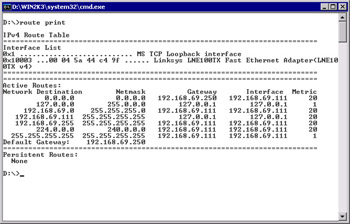
Figure 3.8: Results of the route print Command -
Examine the route table.
-
Notice the Network Destination list. The destinations are described in Table 3.1.
| Description | Network Destination | Netmask | Gateway | Interface | Metric |
|---|---|---|---|---|---|
| Default route | 0.0.0.0 | 0.0.0.0 | 192.168.69.111 | 192.168.69.111 | 20 |
| Loopback network | 127.0.0.1 | 255.0.0.0 | 127.0.0.1 | 127.0.0.1 | 1 |
| Local network | 192.168.69.0 | 255.255.255.0 | 192.168.69.111 | 192.168.69.111 | 20 |
| Local IP address | 192.168.69.111 | 255.255.255.255 | 127.0.0.1 | 127.0.0.1 | 20 |
| Subnet broadcast | 192.168.69.255 | 255.255.255.255 | 192.168.69.111 | 192.168.69.111 | 20 |
| Multicast address | 224.0.0.0 | 240.0.0.0 | 192.168.69.111 | 192.168.69.111 | 20 |
| Limited broadcast | 255.255.255.255 | 255.255.255.255 | 192.168.69.111 | 192.168.69.111 | 1 |
The metric for the loopback adapter and the limited broadcast is always 1. The other addresses have a metric based on the cost of using that route for that network adapter. With multiple network adapters, a multihomed computer, the route table would indicate a different metric for each default route, but only one would be used. Table 3.2 shows a configuration with identical network adapters: one adapter on the 192.168.69.0/24 network and the other on the 192.168.70.0/24 network.
| Description | Network Destination | Netmask | Gateway | Interface | Metric |
|---|---|---|---|---|---|
| Default route | 0.0.0.0 | 0.0.0.0 | 192.168.69.111 | 192.168.69.111 | 20 |
| Default route | 0.0.0.0 | 0.0.0.0 | 192.168.70.100 | 192.168.70.100 | 30 |
| Loopback network | 127.0.0.1 | 255.0.0.0 | 127.0.0.1 | 127.0.0.1 | 1 |
| Local network | 192.168.69.0 | 255.255.255.0 | 192.168.69.111 | 192.168.69.111 | 20 |
| Local IP address | 192.168.69.111 | 255.255.255.255 | 127.0.0.1 | 127.0.0.1 | 20 |
| Local network | 192.168.70.0 | 255.255.255.0 | 192.168.70.100 | 192.168.70.100 | 30 |
| Local IP address | 192.168.70.111 | 255.255.255.255 | 127.0.0.1 | 127.0.0.1 | 30 |
| Subnet broadcast | 192.168.69.255 | 255.255.255.255 | 192.168.69.111 | 192.168.69.111 | 20 |
| Multicast address | 224.0.0.0 | 240.0.0.0 | 192.168.69.111 | 192.168.69.111 | 20 |
| Multicast address | 224.0.0.0 | 240.0.0.0 | 192.168.70.100 | 192.168.70.100 | 20 |
| Limited broadcast | 255.255.255.255 | 255.255.255.255 | 192.168.69.111 | 192.168.69.111 | 1 |
| Limited broadcast | 255.255.255.255 | 255.255.255.255 | 192.168.70.100 | 192.168.70.100 | 1 |
Note that the metric for the default route for the second network, on the adapter for the 192.168.70.100 interface, is higher than the metric for the default route on the 192.168.69.111 interface. This indicates that the 192.168.69.111 network adapter is first in the binding order. Since the metric for the default gateway for the second adapter is higher than the first network adapter, the second gateway is never used and is not necessary.
You can use the route command to add routes and change metrics. The command is route add –p Destination Mask Gateway IF Metric, where:
-
Destination is the network destination address.
-
Mask is the appropriate subnet mask defined for the destination network.
-
Gateway is the address of the router interface used to interface with the network.
-
IF is the interface you want to associate this route to.
-
Metric is the metric for this gateway.
The –p parameter specifies that you want to make this route persistent, so that it will be there if you reset the adapter or restart the machine. If you do not specify –p, the route is temporary and will not be saved.
If you want to delete a route, use the route delete Destination command to remove the destination route from the route table.
You can disable the automatic metric feature by accessing the properties for the desired connection, as follows:
-
Select Internet Protocol (TCP/IP) and click Properties.
-
In the Internet Protocol (TCP/IP) Properties dialog box, click the Advanced button.
-
Uncheck Automatic metric.
-
Provide an Interface metric. The minimum value is 1.
-
Click OK.
-
Run the route print command. What changed? You will notice that all of the metric values are now 1.
You can change the values manually, which can allow you to redirect traffic over a slower interface that would normally have a higher metric.
| Test Day Tip | You should be familiar with the route table, know how to use the route print command, and understand how to use the information in this table to troubleshoot TCP/IP connectivity problems. More details are provided in the “Creating a Subnetting Scheme” and “Troubleshooting IP Addressing” sections later in this chapter. |
|
EAN: 2147483647
Pages: 173