Troubleshooting Hardware and Cabling
|
The most important thing to remember in troubleshooting is to tackle your problems logically so you don't miss any important components or steps. You must confirm the health of all the components that make up the firewall. When addressing PIX firewall problems, you would be best served using the OSI model to guide your efforts. This model was created to guide development efforts in networking by dividing functions and services into individual layers. Per the OSI model, peer layers communicate with each other. For example, the network layer at one host communicates with the network layer at another host.
The approach advocated in this chapter is based on the OSI model shown in Figure 11.1. Problems are tackled starting at the lowest layer, such as validating hardware and cabling at the physical layer. Only when the components at the lower layer have been validated do you turn your attention to components at a higher layer.
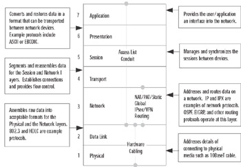
Figure 11.1: The OSI Model
This chapter organizes troubleshooting efforts by the OSI model. Initial troubleshooting starts at Layer 1, the physical layer. Once all physical components have been validated, the troubleshooting focus is shifted to the data link layer components, and so on, up the OSI stack. This controlled approach ensures that we do not miss any facet of our security configuration where the problem could be.
Our first steps in troubleshooting start with physical layer issues. In the context of the PIX firewall, physical components include the firewall hardware and cabling. We start our discussion with a quick overview of the PIX firewall hardware architecture and cabling.
Troubleshooting PIX Hardware
Knowing the details of each PIX firewall model can be helpful in validating your configuration and troubleshooting. Such knowledge can quicken your problem-solving process from the onset by enabling you to determine how to interpret the symptoms you are witnessing. If you use the wrong firewall model for the wrong function, no amount of troubleshooting is going to make it work.
It can be said that your troubleshooting actually starts with your network design and security planning. There are several models of the PIX firewall, each capable of supporting certain numbers and types of network interfaces. Each model has its own upper limit on the number of maximum simultaneous connections, as shown in Figure 11.1. Therefore in Table 11.1 we provide only a snapshot of each model.
| Model | Interface Types Supported | Maximum Number of Interfaces | Failover Support |
|---|---|---|---|
| 501 | Ethernet Fast Ethernet Fixed 10BaseT | Four-port 10/100 switch | No |
| 506E | Ethernet Fast Ethernet | Two fixed 10/100 Ethernet | No |
| 515E | Ethernet Fast Ethernet | Two fixed 10/100 Ethernet Two expansion slots Maximum: Six ports | Yes |
| 525 | Ethernet Fast Ethernet Gigabit Ethernet | Two fixed 10/100 Ethernet Four interface slots Maximum: Eight ports | Yes |
| 535 | Ethernet Fast Ethernet Gigabit Ethernet | Nine interface slots Maximum: 10 ports | Yes |
The Firewall Services Module (FWSM) 1.1 for the Catalyst 6500 series switches provides no physical interfaces. Instead, it provides support for up to 100 VLAN interfaces. For failover support, the FWSM has a dedicated logical interface.
It is important to know whether the PIX firewall you are using is adequate for the demands planned for it. For example, if you have a network on which 100,000 simultaneous connections will be requested through the firewall and you are using a PIX 501, the firewall will immediately become congested and be virtually unusable. In this scenario, no amount of troubleshooting and configuration will enable the PIX 501 to support the load. The capacity of each firewall model is important because it determines the load that can be placed on that firewall. Overloading your firewall is an invitation to crashes or congestion. Underloading a PIX firewall, although great for performance, can be wasteful in terms of unused capacity and monetary return on investment. For example, if you have a network on which there will never be more than 200 simultaneous connections, installing a PIX 535 means that you will not recoup your hardware or software investment, although performance will be fantastic.
The different models support different types of interfaces and in specific quantities, as shown in Table 11.1. Not shown in the table is the fact that Token Ring and FDDI are also supported by several of the models. Cisco ceased PIX firewall support for Token Ring and FDDI networks, starting with PIX software v5.3. As a rule of thumb, do not mix and match interfaces: Configure the PIX firewall as all Token Ring, all Ethernet, or all FDDI. Maintaining such network purity reduces the burden on the PIX firewall since it will not have to translate between the different LAN formats. Only models 515 and up support interfaces other than Ethernet.
The PIX firewall has a system for identifying its network interfaces, which you need to understand in order to troubleshoot the right piece of hardware. Not knowing how interfaces are enumerated and identified can consume valuable time that could otherwise be used for troubleshooting. Figure 11.2 shows how to "read" the network interface identification scheme. Interface card numbering starts with 0 at the right, with card slot numbers increasing as you go left. The slot in which the card is installed determines the number that is given to that card. Ports are numbered top to bottom, starting with 0 for the port at the top of the card.
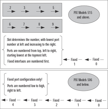
Figure 11.2: PIX Firewall Interface Numbering
For example, the topmost port on an Ethernet interface card installed in Slot 3 would be identified as Ethernet 3/0. Fixed interfaces are first numerically starting on the right at 0, then the next fixed interface to the left is 1. The first installed network interface card would be 2 (as in Slot 2) and its topmost interface is 0. It is important that you learn this scheme not only to identify the specific cards but to also ensure that your configuration and troubleshooting efforts focus on the correct interface.
The memory architecture of the PIX firewall is somewhat similar to that of Cisco routers with the exception that there is no NVRAM memory. The PIX uses flash memory to store the firewall operating system (image) as well as the configuration file. Main memory is used to handle data being processed. As a rule of thumb, the flash memory should be big enough to hold the software image and the configuration. Of all the memory types, main memory can potentially have the most significant impact on performance since it is the working space of the firewall. Main memory is used to store data that is waiting to be processed or forwarded. You can never have too much, and you will definitely notice when you have too little, because packet loss will increase or IPsec traffic will become lossy or laggardly.
Each firewall has visual indicators of operation in the form of light-emitting diodes (LEDs). These LEDs vary by model, but some are common to all. Figure 11.3 shows several PIX firewall LEDs and their meanings. Nurturing your knowledge of these LEDs will enable you to start your Layer 1 troubleshooting from the outside.
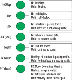
Figure 11.3: PIX Firewall LED Indicators
Study the information in Figure 11.3. The LEDs can be lit, unlit, or flashing, all of which indicate specific conditions. The ACT LED, since it can appear on both the front and rear of the PIX, deserves special attention. On certain models, such as the PIX 506 and 506E, the front LED flashes to indicate that the PIX software image has been loaded. When you're troubleshooting, this indicator would be sufficient to tell you if your software image has been loaded correctly or not at all. On higher-end models such as the 515 and up, the same LED indicates which PIX firewall is active and which is standby in a failover pair. This information can be very useful in determining if your failover configuration is cabled correctly.
During the PIX boot sequence, the power-on self-test (POST) can provide a wealth of information to help determine from the onset whether the PIX firewall is healthy or ill. We use an example boot sequence (which can be seen in the following output) to guide our discussion.
CISCO SYSTEMS PIX-501 Embedded BIOS Version 4.3.200 07/31/01 15:58:22.08 Compiled by morlee 16 MB RAM PCI Device Table. Bus Dev Func VendID DevID Class Irq 00 00 00 1022 3000 Host Bridge 00 11 00 8086 1209 Ethernet 9 00 12 00 8086 1209 Ethernet 10 Cisco Secure PIX Firewall BIOS (4.2) #6: Mon Aug 27 15:09:54 PDT 2001 Platform PIX-501 Flash=E28F640J3 @ 0x3000000 Use BREAK or ESC to interrupt flash boot. Use SPACE to begin flash boot immediately. Reading 1536512 bytes of image from flash. ######################################################################### 16MB RAM Flash=E28F640J3 @ 0x3000000 BIOS Flash=E28F640J3 @ 0xD8000 mcwa i82559 Ethernet at irq 9 MAC: 0008.e317.ba6b mcwa i82559 Ethernet at irq 10 MAC: 0008.e317.ba6c ----------------------------------------------------------------------- || || || || |||| |||| ..:||||||:..:||||||:.. c i s c o S y s t e m s Private Internet eXchange ---------------------------------------------------------------------- Cisco PIX Firewall Cisco PIX Firewall Version 6.2(2) Licensed Features: Failover: Disabled VPN-DES: Enabled VPN-3DES: Disabled Maximum Interfaces: 2 Cut-through Proxy: Enabled Guards: Enabled URL-filtering: Enabled Inside Hosts: 10 Throughput: Limited IKE peers: 5 ****************************** Warning ******************************* Compliance with U.S. Export Laws and Regulations - Encryption. << output omitted >> ******************************* Warning ******************************* Copyright (c) 1996-2002 by Cisco Systems, Inc. Restricted Rights Legend << output omitted >> Cryptochecksum(unchanged): 38a9d953 0ee64510 cb324148 b87bdd42 Warning: Start and End addresses overlap with broadcast address. outside interface address added to PAT pool Address range subnet is not the same as inside interface
The boot sequence identifies the version of the PIX operating system loaded on firmware used to initially boot. In this example, it is 4.3.200. This is important to know because this is the OS that will be used if there is no software image in flash memory. Notice that the first line identifies the model of firewall—information that can be useful if you are checking the firewall remotely.
After the POST is complete, the software image installed in flash is loaded and takes over from that point, as indicated by the "Reading 1536512 bytes of image from flash" line. The PIX firewall runs its checksum calculations on the image to validate it. The OS in the firmware is also validated. This is a layer of protection against running a corrupted operating system. In our example, the image loaded from flash memory recognizes two Ethernet interfaces present on this unit and displays the MAC addresses associated with them.
The boot display provides information about the PIX firewall hardware. The example shows that this particular unit has 16MB of main memory, something that can be a performance factor, as previously discussed. Other types of hardware such as interfaces (quantity and type) and associated IRQ information are identified as well.
Some very useful information about the features supported by this firewall can save you countless hours of frustration. For starters, the exact version of the operating system is identified—v6.2(2), in this case. More important, the features supported by this firewall are clearly enumerated. For example, VPN-DES is supported, whereas VPN-3DES is not. This makes sense since we are looking at a low-end PIX 501 with a limited license for 11 hosts and 5 IKE peers. This firewall supports cut-through proxy and URL filtering.
The last few lines of the boot screen can highlight errors that the operating system encountered when it parsed the configuration file. You should study these messages and determine if and how you must fix them. In our example, we have several problems with the way we have allocated our IP addresses. We also know that the outside interface address is now part of the PAT pool, which is something that we might or might not want, depending on our particular situation.
Once the firewall has completed booting, you can continue your hardware verification efforts using commands provided by Cisco. These are several commonly used commands to check the composition and health of your PIX firewall at Layer 1. The following output illustrates the show version command, which provides a quick snapshot of your PIX firewall. Information provided by this command includes interface information, serial numbers, and so on, as shown in the command output. Use this command when you need information about your firewall's software and hardware. Some of the output is similar to what you saw during the boot sequence.
PIX1> show version Cisco PIX Firewall Version 6.2(2) Cisco PIX Device Manager Version 2.1(1) Compiled on Fri 07-Jun-02 17:49 by morlee PIX1 up 23 secs Hardware: PIX-501, 16 MB RAM, CPU Am5x86 133 MHz Flash E28F640J3 @ 0x3000000, 8MB BIOS Flash E28F640J3 @ 0xfffd8000, 128KB 0: ethernet0: address is 0008.e317.ba6b, irq 9 1: ethernet1: address is 0008.e317.ba6c, irq 10 Licensed Features: Failover: Disabled VPN-DES: Enabled VPN-3DES: Disabled Maximum Interfaces: 2 Cut-through Proxy: Enabled Guards: Enabled URL-filtering: Enabled Inside Hosts: 10 Throughput: Limited IKE peers: 5 Serial Number: 406053729 (0x1833e361) Running Activation Key: 0xc598dce8 0xf775fc1c 0xbd76cee8 0x3f41e74b Configuration last modified by at 06:28:16.000 UTC Thu Feb 7 2036
The first part of this command identifies the version of OS that is loaded and being used as well as the version of PIX Device Manager (PDM). Next in the output you see the amount of time that has elapsed since the unit was powered on. This information is useful because it can show if your PIX firewall was rebooted or power-cycled recently. The show version command gives additional details such as the model, amount of available memory, and CPU speed and type. It also tells you the amount of flash and BIOS memory. When troubleshooting, you should know this information in order to determine if the demands placed on the unit are reasonable. This unit has two Ethernet interfaces; notice that their MAC addresses are enumerated. The last part of the output provides the serial number of this unit as well as the activation key used to activate the image. Although it is not critical to troubleshooting, it might be necessary to provide this information to Cisco TAC should you need to call them for assistance.
When you're troubleshooting, the show version command should be one of the first (if not the first) commands that you execute to obtain a component inventory of the PIX firewall. It is especially vital that you know which features are supported by the firewall before you begin troubleshooting; otherwise, you could squander valuable time trying to determine why an unsupported featured is not working. When looking at the output of the show version command, ensure that you note the MAC addresses of the interfaces; this information can be useful in resolving Layer 2 to Layer 3 address-mapping issues.
The show interface command shown in the following output is a tool that can provide information applicable to different layers of the troubleshooting process. It provides details on the network interfaces. As with Cisco routers, this command enables you to check the state of an interface and determine if it is operational. You can also see what each interface is labeled. This command and its associated output are discussed later in the chapter.
interface ethernet1 "inside" is up, line protocol is up Hardware is i82559 ethernet, address is 0008.e317.ba6c IP address 10.10.2.1, subnet mask 255.255.255.0 MTU 1500 bytes, BW 10000 Kbit full duplex 4 packets input, 282 bytes, 0 no buffer Received 0 broadcasts, 0 runts, 0 giants 0 input errors, 0 CRC, 0 frame, 0 overrun, 0 ignored, 0 abort 4 packets output, 282 bytes, 0 underruns 0 output errors, 0 collisions, 0 interface resets 0 babbles, 0 late collisions, 0 deferred 0 lost carrier, 0 no carrier input queue (curr/max blocks): hardware (128/128) software (0/1) output queue (curr/max blocks): hardware (0/1) software (0/1)
The output of the show interface command has useful applicability to the troubleshooting process. However, if you do not know how to read the output, the plethora of information presented will be of little value. One of the first things you need to determine with this command is if you want a particular interface to serve a particular network. In our example, Ethernet 1 is considered the "inside" network. As a part of our troubleshooting, we would ensure that Ethernet 1 is indeed connected to our "inside" network. The MAC address assigned to this interface is listed, as is the type of interface (Ethernet).
The maximum transmission unit (MTU) specifies the maximum packet size that this interface can pass without having to fragment it. Anything larger will be broken into the appropriate number of frames to enable passage through this interface. This can be an issue if you have devices that send large frames. This command also verifies the duplex operation of the interface; recall that the interface also has a full-duplex LED that you can use. Duplex mismatches between the PIX and LAN switches are a common problem and can be a headache. Ensure that the speed and duplex settings match on the PIX firewall and the switch.
There is a packet counter for inbound and outbound packets. This indicator tracks how many packets have transited this interface and the total number of bytes that these packets constituted. The "no buffer" counter is especially important to troubleshooting because it indicates the number of times that there were no buffers to store incoming packets until they could be processed by the CPU. If this counter increments, the interface is receiving more packets than it can handle. In this case, you need to upgrade to a higher-capacity interface or throttle back the incoming traffic. Each interface also has counters for tracking broadcasts and errors:
-
broadcasts Packets sent to the Layer 2 broadcast address of this interface.
-
runts Packets received that were less than Ethernet's 64-byte minimum packet size.
-
giants Packets received that were greater than Ethernet's 1518-byte maximum packet size.
-
CRC Packets that failed the CRC error check. Test your cables and also ensure there is no crosstalk or interference.
-
frame Framing errors in which an incorrect Ethernet frame type was detected. Make sure you have the appropriate frame type configured on all your hosts.
-
overrun Input rate exceeded the interface's ability to buffer.
-
ignored/abort These counters are for future use. The PIX does not currently ignore or abort frames.
-
collisions Number of transmitted packets that resulted in a collision. On a half-duplex interface, collisions do not necessarily indicate a problem, since they are a fact of Ethernet life.
-
underrun Indicates that the PIX was too overwhelmed to get data fast enough to the network interface.
-
babbles This is an unused counter. Babbles indicate that the transmitter has been on the interface longer than the time taken to transmit the largest frame.
-
late collisions Collisions that occurred after the first 64 bytes of transmission. Unlike normal collisions, these indicate a problem. Usually, late collisions are caused by faulty cabling, long cables exceeding specification, or an excessive number of repeaters.
-
deferred Packets that had to be deferred because of activity on the link. This generally indicates a congested network since the interface has to keep backing off to find an available transmit window to send; this can become a perpetuating problem that consumes buffer space as outgoing packets have to be stored until a transmit windows opens.
-
lost carrier The number of times the signal was lost. This can be caused by issues such as a switch being shut off or a loose cable.
-
no carrier This is an unused counter.
| Note | On a full-duplex interface, you should never see collisions, late collisions, or deferred packets. |
The queue counters refer to the amount of data (measured in bytes) queued for reception and transmission. These counters provide a snapshot of what is currently queued at the time the command is issued. The queues will be depleted if the firewall receives more traffic than it can handle. When a packet is first received at an interface, it is placed in the input hardware queue. If the hardware queue is full, the packet is placed in the input software queue. The packet is then placed into a 1550-byte block (a 16384-byte block on 66MHz Gigabit Ethernet interfaces) and passed to the operating system. Once the firewall has determined the output interface, the packet is placed in the appropriate output hardware queue. If the hardware queue is full, the packet is placed in the output software queue.
In either the input or output software queue, if the maximum blocks are large, the interface is being overrun. If you notice this situation, the only way to resolve it is to reduce the amount of traffic or to upgrade to a faster interface.
Troubleshooting PIX Cabling
After you have ascertained that the PIX hardware is functional, your next step in troubleshooting should be to corroborate cabling. Unlike routers, which use a wide variety of cables, the PIX firewall has a relatively limited number of cable types that we care about in the context of troubleshooting: Ethernet and failover cables.
Certain models of the PIX firewall support Token Ring and FDDI networks in older software versions (up to v5.3). Cisco has discontinued the sale of Token Ring and FDDI for PIX firewalls starting August 2001 and June 2001, respectively. Support is slated to cease in August 2006 and June 2006, respectively. We do not discuss Token Ring or FDDI cables in this book.
Regardless of the cables you are troubleshooting, you should adopt a structured approach. Table 11.2 summarizes some steps you should first take to check your cabling. Ensure that you perform these steps to avoid missing a minor cabling glitch that could be causing a major problem.
| Problem | Troubleshooting Step |
|---|---|
| Correct cable connected to the correct interface? | Check cable and verify slot and port number. |
| Correct end of cable connected to correct interface? | Failover cable only: Primary end to the primary firewall and secondary end to the secondary firewall. |
| Correct cable type connected to equipment? | Cross cables, rollover cables, and so on to the correct ports. |
| Cable pinouts correct? | Visually inspect and check with cable tester. |
| Cable verified as good? | Test with a cable tester or swap with known good equipment and test. |
All PIX firewalls support 10Mbps or 100Mbps Ethernet, but only the high-end models such as 525 and 535 support Gigabit Ethernet. This makes sense when you consider the capacity available on each model: The lower-end models would be overwhelmed by the addition of even a single Gigabit Ethernet interface. As of this writing, the PIX 535 provides 9Gbps of clear-text throughput, the 525 provides 360Mbps, the 515 provides 188Mbps, the 506 provides 20Mbps, and the 501 provides 10Mbps. At the physical layer, the primary issue you will face is to ensure that the correct Ethernet cables are being used and that they are wired correctly. Figure 11.4 shows the pinouts that you should be using for Ethernet and Fast Ethernet cables.
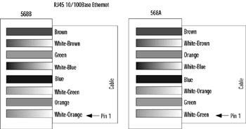
Figure 11.4: Ethernet Cable Pinouts
Two wiring schemes for the RJ45 standard are used for 10/100 Ethernet: TA568A and TA568B shown in Figure 11.4. It is important that your cable adhere to one of these standards to prevent interference (crosstalk). If you were to dismantle a RJ45 cable, you would see that there are four pairs of wires. In each pair, the two wires are twisted around each other to minimize crosstalk. If you were to pick wires at random and crimp them into the RJ45 connector to make an Ethernet cable, chances are you would experience problems with your cables. The wiring scheme of the TA568A/B standard is optimized to prevent such interference.
The process of troubleshooting cabling is relatively easy because there are numerous cable testers on the market, ranging from simple pin-checking devices to expensive, full-featured testers. The time that these devices save well justifies their initial cost.
The first step in verifying 10/100 Ethernet copper cable is to visually inspect the cable for breaks. Check the wiring pinouts against Figure 11.4. If they match and appear to be in good physical shape, the next step is to test the cable using a cable tester. Most cable testers will allow you to map the wiring; pin mismatches are a common problem. If you still have problems with the cable after it passes the cable tester, try using a different cable. Chances are, you have a rare bad mix of plastic and metal composition that went into the making of that cable and it is interfering with the cable's ability to transport electrons. If you do not have a cable tester and are not sure of the cable, replace it.
PIX firewall models 525 and 535 support full-duplex Gigabit Ethernet (GE). The GE interfaces use SC multimode fiber optic cables: one strand for receive and the other for transmit, as shown in Figure 11.5. It is important that you cable the wire with the correct cable to the correct connector.
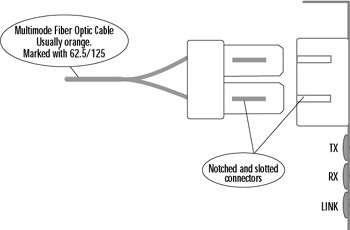
Figure 11.5: Gigabit Ethernet SC Fiber Optic Connector
Fortunately, the SC connector Cisco uses prevents us from inserting the cable incorrectly. The connector on the cable is notched to fit the slotted jack on the interface card. You need to understand a little about fiber optic cables to effectively use them with your PIX firewall. Fiber optic is either single mode or multimode. The PIX firewall GE interfaces use multimode fiber, which refracts light, as shown in Figure 11.6.
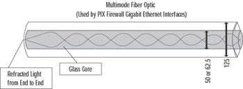
Figure 11.6: Multimode Fiber Optic Cable
The fiber optic industry adheres very strictly to its standards. As a result, usually you can visually determine whether you have a multimode or single-mode fiber optic cable attached by its color. Single-mode cables are yellow and have markings down their sides indicating their width in microns. Multimode fiber optic cable used by PIX firewalls is orange and is numerated with either 50 or 62.5 microns, indicating the size of its glass core down which light is sent. The cladding packed in the glass core is the same size for both cables: 125 microns. This is a general rule of thumb only; some manufacturers offer custom colors or do not adhere to the standard color scheme.
As with twisted-pair cable for Ethernet and Fast Ethernet, you can use a cable tester to verify your fiber optic cable. Unlike copper cables, fiber optic cables are very unforgiving of failure to adhere to tight specifications. If you made the cable that you are using and it is not working, odds are very good that you made an error (poor crimping, insufficient polishing, or the like). It is in such situations that the value of a good cable tester becomes apparent. Unless you are a certified fiber optic technician, it is a good idea to leave the fiber optic cable making to the professionals who specialize in it.
|
EAN: 2147483647
Pages: 240
- Structures, Processes and Relational Mechanisms for IT Governance
- A View on Knowledge Management: Utilizing a Balanced Scorecard Methodology for Analyzing Knowledge Metrics
- Technical Issues Related to IT Governance Tactics: Product Metrics, Measurements and Process Control
- The Evolution of IT Governance at NB Power
- Governance Structures for IT in the Health Care Industry