Troubleshooting Connectivity
|
In order to perform its duties, a PIX firewall must be able to reach its destinations. Its ability to pass traffic from source to destination is affected by factors such as routing, address translation, access lists, and so on. Translation can be particularly critical since all addresses must be translated in order for internal and external networks to communicate with each other.
Get in the habit of executing clear xlate to clear any current translations whenever you make a change to NAT, global, static, access lists, conduits, or anything that depends on or is part of translation. Since translation is mandatory on PIX firewalls, this covers just about any feature you can configure. Failure to delete existing translations will cause unexpected behavior.
Remember how interfaces of different security levels work with each other. Traffic from a higher security level to a lower security level is permitted by default but still requires translations to be set up. Traffic from a lower security level to a higher security level (such as outside to inside) requires an access list or conduit, as well as corresponding translations.
It cannot be reinforced enough that you should get in the habit of checking log messages. Syslog provides an ongoing, real-time report of activities and errors—information that can be vital to troubleshooting success. The information syslog provides can help you take your first or next step, so ensure that you develop your syslog reading habits. This can be particularly useful in identifying errors with access lists and translation. For example, if a host on a lower security-level interface wants to communicate with a host on a higher security-level interface and translation is enabled for it, but no conduit or access list is configured, the following message will be logged:
106001: Inbound TCP connection denied from x.x.x.x/x to x.x.x.x/x
This is your first clue that you need an access list or conduit to permit this access. If the reverse is the case (access list or conduit is present, but no translation is configured), the following message will be logged:
305005: No translation group found for...
For more information about syslog message numbers and descriptions, see www.cisco.com/univercd/cc/td/doc/product/iaabu/pix/pix_61/syslog/pixemsgs.htm.
Checking Addressing
As with any IP device, unless basic IP addressing and operation are configured correctly and working, none of your PIX firewall troubleshooting efforts regarding routing, access lists, and translation will matter. This point cannot be overstressed: Addressing must be correct in order for the PIX firewall to function. Figure 11.7 shows PIX1 and PIX2 connected to each other.
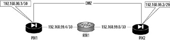
Figure 11.7: IP Addressing Problem
In Figure 11.7, there is an addressing problem on the LAN connecting the two firewalls (which is labeled DMZ in the configuration). For starters, PIX1 has a subnet mask of /30, while FW2 has a mask of /29 for the DMZ network (192.168.99.0), a common network between them. This is confirmed using the show ip address command on both firewalls. Notice the differences highlighted in the following command output:
PIX1# show ip address System IP Addresses: ip address outside 192.168.99.5 255.255.255.252 ip address DMZ 192.168.99.1 255.255.255.252 Current IP Addresses: ip address outside 192.168.99.5 255.255.255.252 ip address DMZ 192.168.99.1 255.255.255.252 PIX2# show ip address System IP Addresses: ip address outside 192.168.99.9 255.255.255.252 ip address DMZ 192.168.99.2 255.255.255.248 Current IP Addresses: ip address outside 192.168.99.9 255.255.255.252 ip address DMZ 192.168.99.2 255.255.255.248
The fix here is simply to correct the mask on PIX2. As on Cisco routers, the show interface command can also be used to check addressing on your PIX firewall, as shown in the following command output:
PIX1# show interface interface ethernet0 "DMZ" is up, line protocol is up Hardware is i82559 ethernet, address is 0008.e317.ba6b IP address 192.168.99.1, subnet mask 255.255.255.252 MTU 1500 bytes, BW 100000 Kbit half duplex 2 packets input, 258 bytes, 0 no buffer Received 0 broadcasts, 0 runts, 0 giants 0 input errors, 0 CRC, 0 frame, 0 overrun, 0 ignored, 0 abort 11 packets output, 170 bytes, 0 underruns, 0 unicast rpf drops 0 output errors, 0 collisions, 0 interface resets 0 babbles, 0 late collisions, 0 deferred 0 lost carrier, 0 no carrier input queue (curr/max blocks): hardware (128/128) software (0/1) output queue (curr/max blocks): hardware (0/2) software (0/1)
Regardless of the method you use, verify that all interface IP addresses are correct before proceeding any further in your troubleshooting efforts. Incorrect addressing will prevent advanced features of the PIX firewall from working, even if you configure them correctly. After all, all traffic must pass through at least two interfaces, and the interfaces must be addressed correctly.
Checking Routing
The inability to reach a destination is a prime indicator of routing problems. Such problems can be complex to troubleshoot, but using a structured approach to isolate the cause can ease troubleshooting. The PIX firewall uses both static and dynamic routing. For dynamic routing, the PIX supports only RIP as a routing protocol; otherwise, the routing information it has is manually entered in the form of static routes. We open our routing verification discussion with a review of the various routing options available on the PIX firewall and how they interact.
| Note | The FWSM 1.1 for the Catalyst 6500 series switches also supports OSPF for dynamic routing. OSPF is not discussed in this chapter. |
First, let's review the techniques you use to configure routing on your PIX, starting with the simplest (default route) and onward to using RIP to learn routes. In the simplest configuration, the PIX firewall is configured only with a static default route. For example:
route outside 0.0.0.0 0.0.0.0 192.168.99.2 metric 1
This command states that all traffic that does not match any of the local interfaces will be sent to the next hop of 192.168.99.2. Assuming this is the only static route configured on the firewall in Figure 11.8, all traffic destined for a nonlocal interface on the PIX firewall will be forwarded to RTR1 to reach its final destination. A single static route such as this one works well for the simple configuration in Figure 11.8, but what happens if we have a more complex architecture, such as the one shown in Figure 11.9?
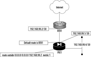
Figure 11.8: Default Route Example
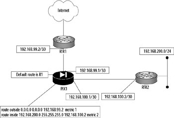
Figure 11.9: Static Routes
Figure 11.9 shows that the traffic from PIX1 must be forwarded to R2 to reach 192.168.200.0/24. If we used only a default route, any traffic for 192.168.200.0/24 would be sent to RTR1 and would never reach its destination. We can resolve this issue by adding a static route on PIX1 so it knows where to forward traffic destined to 192.168.200.0/24. This is accomplished by adding another (more specific) route to the PIX1 configuration:
route inside 192.168.200.0 255.255.255.0 192.168.100.2 metric 2
In addition to using these static methods for routing, the PIX firewall supports dynamic routing using RIP v1 or v2. Unlike the wide range of options available for RIP on Cisco routers, the RIP commands on the PIX firewall are sparse.
[no] rip <if_name> default [no] rip <if_name> passive [no] rip <if_name> version {1 | 2} [no] rip <if_name> authentication [text | md5] key <key_id> We will not spend an inordinate amount of time debating the merits of RIP as a routing protocol. Suffice to say, the default keyword means that the PIX firewall advertises a default route out that interface. The passive keyword configures RIP to listen on, but not advertise out, a particular interface. The version keyword is used to set the version of RIP that the PIX firewall will use. RIP peers can authenticate each other to ensure that they send and receive updates from legitimate peers. RIP is enabled on a per-interface basis.
In Figure 11.10, we have replaced our statically routed network with RIPv2. Notice how this replacement has changed the routing picture, enabling the PIX firewall to better adapt to network changes.
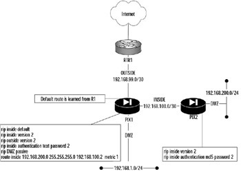
Figure 11.10: RIP Routing
On PIX firewalls, RIP does not advertise from interface to interface. In Figure 11.10, PIX1 is listening for updates on its DMZ network and is learning any routes that might be present behind that network. As a result, PIX1 will know how to reach those networks. Since the passive keyword is used, PIX1 will not advertise any RIP routes out its DMZ interface. However, PIX1 will not advertise those routes to PIX2 or RTR1. This is a limitation of RIP in the PIX firewall that needs to be resolved by adding a default route to PIX2 (which our configuration has) and a static route on R1 to reach any networks behind PIX1's DMZ interface. What PIX1 will advertise is any of its directly connected interfaces and default routes, so R1 and PIX2 will be able to reach any directly connected network on PIX1. PIX2 will be able to reach the networks behind PIX1's DMZ interface since PIX1 is the default route for PIX2.
This limitation of RIP might not be such a limitation. In actual practice, any addresses that leave or enter PIX1 related to the outside interface would actually be translated. In the case of RTR1, it does not need to know about the networks behind PIX1's DMZ network since those addresses would be translated to a public address, which RTR1 would know to send to PIX1 for processing.
One problem is quite apparent in our configuration in Figure 11.10. There is an authentication mismatch between PIX1 and PIX2. PIX1 is using a clear-text password for authentication, while PIX2 is using MD5. Although the password is the same on both sides, the encryption technique is different. The result is that RIP routing will not work between them, as disagreement on the password encryption technique will prevent the peers from authenticating to each other, which will prevent the exchange and acceptance of routing updates.
Another potential showstopper that you need to be alert for is conflicting versions of RIP. The most significant difference is that RIPv1 broadcasts to an all-hosts broadcast address of 255.255.255.255. RIPv2 generally multicasts to the reserved IP multicast address of 224.0.0.9. Additionally, v2 supports authentication, whereas v1 does not. When troubleshooting routing problems with RIP, look at the configuration of the devices where routing is not working, and check to make sure that all your routing peers agree on the version. If you are using RIPv2 with authentication, ensure that the same password and the same encryption method are used on both. Support for RIPv2 was introduced in PIX software v5.1. Prior versions cannot interoperate with RIPv2 speakers, so keep the RIP version differences in your mind as you troubleshoot. Support for RIPv2 multicast was introduced in v5.3. Prior versions could only handle broadcasts.
Having reviewed how the PIX gets it routes, we now turn our attention to troubleshooting when the PIX is unable to reach a particular destination or when it does not have a route to a particular destination. Your tools of choice for troubleshooting routing issues on the PIX are primarily show route, show rip, and ping. Determine if there is a reachability problem by attempting to ping the destination. If that fails, use show route to determine if there is a route (static or RIP) to reach the network. You can use the show rip command to confirm your dynamic routing configuration. The ping command should be a litmus test to verify that the destination cannot be reached. The syntax of the ping command is as follows:
ping [<if_name>] <ip_address>
For example:
PIX1# ping 192.168.99.2 192.168.99.2 response received -- 20ms 192.168.99.2 response received -- 20ms 192.168.99.2 response received -- 20ms
Does the PIX have a default route, a static route, or even a dynamically learned route? Check your routing table with the show route command. For example:
PIX1# show route outside 192.168.99.0 255.255.255.252 192.168.99.1 1 CONNECT static inside 192.168.100.0 255.255.255.252 192.168.100.1 1 CONNECT static DMZ 192.168.1.0 255.255.255.0 192.168.1.1 1 CONNECT static
In our case, 192.168.99.2 is on our directly connected outside network. To perform a side-by-side comparison of RIP peers, use the show rip command. In the following output, we are looking at the RIP configuration of PIX1 and PIX2; notice how the mismatches between the versions and authentication technique are readily apparent.
PIX1# show rip rip inside default rip inside version 1 rip outside version 2 rip inside authentication text cisco1 2 rip DMZ passive PIX2# show rip rip inside version 1 rip outside version 1 rip inside authentication md5 cisco2 2 rip DMZ passive
The result of this configuration is that RIP will not work between PIX1 and PIX2 since they do not agree on any of the parameters. A corrected configuration that will work is provided in the following output.
PIX1# show rip rip inside default rip inside version 2 rip outside version 2 rip inside authentication md5 cisco2 2 rip DMZ passive PIX2# show rip rip inside version 2 rip outside version 2 rip inside authentication md5 cisco2 2 rip DMZ passive
We conclude our discussion of RIP with the clear rip command, which should only be used when you have made a definite decision that you no longer need to use RIP. This command removes all existing RIP commands and parameters from the configuration.
Failover Cable
Cisco provides a wonderful feature called failover, wherein the configuration and operations of one firewall are mirrored to a backup firewall. When using standard failover with the failover cable, it is the cable that determines which firewall is the primary and which is the secondary unit in a pairing. The cable makes this determination based on which end is plugged into which firewall.
As part of your PIX firewall troubleshooting knowledge, you need to know the pinout scheme used by this cable. To that end, we have provided a detailed schematic in Figure 11.11. If failover is not working, you need to know what your cable configuration should look like when you analyze it with a cable tester.
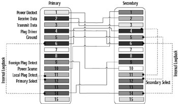
Figure 11.11: Failover Cable Pinout
Although all the wires in the DB15 connector at each end are important, you can see that certain wires are cross-connected at each end to distinguish the primary end from the secondary end. The primary firewall is configured by cross-connecting wire 11 (local plug detect) to wire 12 (primary select). The secondary firewall is determined by cross-connecting wire 12 (secondary select) to wire 5 (ground). Knowing the wiring scheme can enable you to not only to check your failover cable, but to also build one from scratch if necessary.
Checking Translation
The PIX firewall performs address translation. In order for internal networks to communicate with external networks, and vice versa, addresses must be translated. Translation is not optional. The translation is the act of translating one IP address to another, which can be configured as one to one (NAT) or many to one (PAT).
| Note | To pass traffic through the PIX traffic, you must translate it, even if this means you will translate IP addresses to themselves. |
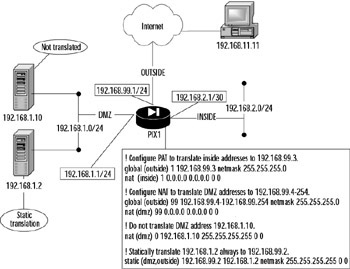
Figure 11.12: Translation in Action
In this chapter, we quickly review some key concepts using Figure 11.12, which shows all the possible translation scenarios that you can have on your PIX firewall.
Figure 11.12 shows a PIX firewall, PIX1, connected to three networks: inside, DMZ, and outside. The addresses on the inside network are serviced using PAT. The DMZ has two hosts on it: one that is not translated (in reality, it is just translated to itself) and one that is statically translated. All remaining addresses on the DMZ are dynamically translated using a range of IP addresses associated with the outside network.
In the PIX world, translation is necessary to provide connectivity. When translation does not work, you need to know where to start and finish your troubleshooting. Cisco provides several commands that you can use to validate various aspects of translation. We start with a review of the various translation configuration commands and how to effectively institute them. Let's review the configuration in Figure 11.12.
First, look at which private addresses are being translated to which public addresses. This information will determine if the translation parameters have been configured correctly. Two commands used to perform this task are show nat and show global:
PIX1# show nat nat (dmz) 0 192.168.1.10 255.255.255.255 0 0 nat (inside) 1 0.0.0.0 0.0.0.0 0 0 nat (dmz) 99 0.0.0.0 0.0.0.0 0 0 PIX1# show global global (outside) 99 192.168.99.4-192.168.99.254 netmask 255.255.255.0 global (outside) 1 192.168.99.3 netmask 255.255.255.0
Our NAT configuration specifies a nontranslation for the DMZ server at address 192.168.1.10 network (as evidenced by the nat 0 command). The nat 99 specifies that all remaining addresses in the DMZ should be translated. The global command defines two pools of addresses to be used for translation purposes. The numerical ID is referenced by the NAT command to perform the actual translation. The global 99 command is used for NAT, whereas global 1 with its single IP address is used for PAT. In actual practice, you would know at this point if you had configured the translation parameters correctly. Both of these commands provide enough data for you to make this determination. Once you have corrected any errors (the most common being typos or incorrect IP addresses), you can then check to see if connections are being made and translated. The next step is to determine if connections have been made by using the show conn detail command:
PIX1# show conn detail 1 in use, 1 most used Flags: A - awaiting inside ACK to SYN, a - awaiting outside ACK to SYN, B - initial SYN from outside, D - DNS, d - dump, E - outside back connection, f - inside FIN, F - outside FIN, G - group, H - H.323, I - inbound data, M - SMTP data, O - outbound data, P - inside back connection, q - SQL*Net data, R - outside acknowledged FIN, R - UDP RPC, r - inside acknowledged FIN, S - awaiting inside SYN, s - awaiting outside SYN, U - up TCP outside:192.168.11.11/24 dmz:192.168.99.2/80 flags UIO
The workstation has established a connection to our HTTP server on the DMZ network (as confirmed by its destination port, 80). Notice that the workstation established the connection to the public address of this server rather than to its internal DMZ address (192.168.1.2), which it cannot reach. Now we have a valid connection attempt, but has the translation taken place as it should? To determine that, we must use the next command in our toolbox, show xlate detail:
PIX1# show xlate detail 1 in use, 1 most used Flags: D - DNS, d - dump, I - identity, i - inside, n - no random, o - outside, r - portmap, s - static TCP NAT from DMZ:192.168.1.2/80 to outside:192.168.99.2/80 flags ri
This command displays a current listing of active translation slots. The output of this command confirms that our host's attempt to access the Web server at 192.168.99.2 has resulted in the correct translation to 192.168.99.2. Such verification is particularly important if you are providing services that must be accessible by outside users.
There is one more command that we can use to gather information about our translation operations. It is a debug command and, as such, should be used sparingly to conserve firewall resources. This command can serve two functions: tracking and decoding packet-level activity between hosts (such as the traffic between our workstation and the Web server), or it can be used if you need to determine exactly which addresses need to be translated and granted access. The latter part of this statement needs to be explained more fully. Assuming that we did not know exactly what the source address of our workstation was going to be, it would be helpful to capture information on its attempts to connect to the DMZ Web server. The command that can provide us with the copious information we need is the debug packet command. The syntax of the command is as follows:
debug packet <if_name> [src <source_ip> [netmask <mask>]] [dst <dest_ip> [netmask <mask>]] [[proto icmp] | [proto tcp [sport <src_port>] [dport <dest_port>]] | [[proto udp [sport <src_port>] [dport <dest_port>]] [rx | tx | both]
In our case, the command we would actually enter to find out which addresses are attempting to use our Web server is:
PIX1(config)# debug packet outside src 0.0.0.0 netmask 0.0.0.0 dst 192.168.99.2 netmask 255.255.255.0 rx
This command captures packet data that comes into the outside interface destined for the Web server's public IP address. Since we do not know exactly which protocols (TCP, UDP, or ICMP) will be used, we have opted not to specify one. After we have captured our data, we can then determine which translation parameters we need to enter.
Checking Access
The PIX firewall provides several mechanisms for controlling access through it. In this section, we cover several of these mechanisms and discuss some ways to monitor and verify their functionality. The default state of the PIX firewall is to permit access to sessions originated from a higher security-level interface to a lower security-level interface, as long as a translation is configured. Traffic that originates from a low security-level interface to a high security-level interface has to be specifically permitted using conduits or access lists (and of course, translations).
The conduit command is a special form of an access list. It is used to permit traffic from a lower security-level interface to a higher security-level interface. Figure 11.13 shows several common access scenarios with various hosts needing access to each other. The Web client (security level 0) will be accessing the Web server (security level 50); the default behavior of the PIX firewall is to forbid such traffic. The workstation (security level 100) needs to access Internet resources using the outside network. Figure 11.13 also provides the configuration necessary to enable the access needed by the various hosts and servers, which are denoted A, B, and C for ease of discussion. The assumption is that all translation parameters have been configured and are working correctly, which enables us to focus on specific access issues. The addresses shown are used for discussion, but in your mind, assume that they have been translated.
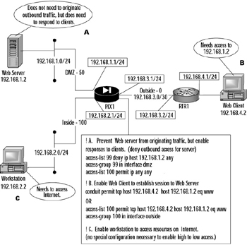
Figure 11.13: Access Scenario
The Web server needs to be prevented from originating sessions to networks located off the DMZ network, but must be able to respond to service requests from the Web client located on the outside network. To accomplish this goal, we created an access list to deny 192.168.1.2 from accessing anything and applied it to the DMZ interface. Then we created a conduit to permit 192.168.4.2 to access Web services (TCP port 80) on 192.168.1.2. Alternatively, we could have used an access list to accomplish the same thing, as shown in Figure 11.13. The option to use access lists instead of conduits is available only on PIX firewall software v5.1 and later. It is important to note that Cisco recommends that you avoid mixing access lists and conduits. Additionally, access lists take precedence over conduits. In the PIX environment, access lists have one and only one direction: in. The access-group command applies the access list to traffic coming into the designated interface.
The inside workstation (denoted by C) needs to be able to access resources on the Internet. The inside interface has a security level of 100, the highest possible security level. Recall that hosts on higher security-level interfaces can access hosts on lower security-level interfaces without any special configuration to permit responses to return. This is exactly the case with this workstation, so we need no special configuration.
Problems with lack of access become apparent when machines are unreachable. Since access control mechanisms such as access lists and conduits have a close interdependent relationship with translation, you should validate the translation configuration first. Once that is confirmed, begin your access troubleshooting. Access problems can include typos, overly restrictive or loose access lists or conduits, the wrong networks being denied or permitted access, or access lists applied to the wrong interface. Here we demonstrate several commands that you can use to verify access.
Recall that a conduit is a hole in your firewall security that permits hosts on a lower security level access to resources on a higher security level. The main command for verifying conduit configuration is show conduit. For example:
PIX1# show conduit conduit permit tcp host 192.168.4.2 host 192.168.1.2 eq www (hitcnt=3)
This conduit permits 192.168.4.2 to access the Web server at 192.168.1.2. This is the only PIX command for checking conduits. With the option provided in v5.1 to use access lists instead, conduits are gradually being phased out in favor of the more standard access lists. When that happens, you can remove all conduit parameters from your PIX firewall configuration using the clear conduit command. This is a slightly schizophrenic command, depending on where it is it used. If used at the privileged command prompt as clear conduit counters, it "zeroizes" the hit counter. If clear conduit is used in the Configuration mode, it removes all conduit statements from the PIX firewall configuration.
Access lists, another access control mechanism, offer more troubleshooting tools than conduits do. The show access-list command can be used to confirm which access lists are configured on the PIX firewall and what they are permitting and denying:
PIX1# show access-list access-list 99; 2 elements access-list 99 deny ip host 192.168.1.2 any (hitcnt=1) access-list 99 permit ip any any (hitcnt=0) access-list 100 permit tcp host 192.168.4.2 host 192.168.1.2 eq www (hitcnt=5)
This command was executed on the firewall in Figure 11.13. Recall that an access list only affects incoming traffic to an interface. Once you have confirmed that the access list is configured as it should be, the next troubleshooting step is to verify that it has been applied to the correct interface. Cisco provides the show access-group command for this purpose. For example:
PIX1# show access-group access-group 99 in interface dmz access-group 100 in interface outside
The in keyword is mandatory and serves as a reminder that the access list is applied only to traffic coming into the interface. Cisco provides a debug command for troubleshooting access list events as they occur. Beware that when you use this command, it debugs all access lists. There is no option to do real-time monitoring of a particular access list. This can generate copious amounts of data, especially if you execute it on a high-traffic PIX firewall. As with any debug command, use it sparingly and only if you know what you are searching for. The debug access-list command can provide feedback on your access list and whether it is permitting or denying the traffic that it should. The command syntax is as follows:
debug access-list {all | standard | turbo} Another access control mechanism is outbound/apply, but Cisco recommends that it not be used. Cisco recommends that you use the access list features of the PIX firewall instead. The outbound/apply commands were the precursor to the access list feature and are still available and supported by the PIX firewall software. However, these commands suffer from a very awkward syntax, are fairly limited, and can be frustrating to troubleshoot. The outbound command was designed to control access of inside users to outside resources. Having said all that, a working familiarity with the command is handy for when you encounter situations in which it is still used. The syntax for the outbound command is as follows:
outbound <ID> {permit | deny | except} <ip_address> [<netmask>] [<port> [-<port>]] [tcp | udp| icmp] The ID parameter specifies a unique identifier for the outbound list. You can either configure a permit rule, a deny rule, or an except rule (which creates an exception to a previous outbound command). Unlike access lists, outbound lists are not processed from top to bottom. Each line is parsed regardless of whether there is a match or not. Cisco recommends that all outbound lists start with a deny all (deny 0 0 0), followed by specific statements allowing access. The net effect is cumulative. How the PIX firewall uses the outbound list depends on the syntax of the apply command:
apply [<interface>] <OUTBOUND_LIST_ID> {outgoing_src | outgoing_dest} When the outgoing_src parameter is used, the source IP address, destination port, and protocol are filtered. When the outgoing_dst parameter is used, the destination IP address, port, and protocol are filtered. It is vital that you understand that the outbound list does not determine whether the IP address it uses is either a source or a destination; the apply command does that. This can be a major troubleshooting headache because an outbound list could be configured correctly but might not work because the apply command is configured incorrectly. When troubleshooting _outbound, ensure that you check the apply configuration as well. When multiple rules match the same packet, the rule with the best match is used. The best-match rule is based on the netmask and port range. The stricter the IP address and the smaller the port range, the better a match it is. If there is a tie, a permit option takes precedence over a deny option.
Here is an example of outbound/apply:
PIX1(config)# outbound 99 deny 0 0 0 PIX1(config)# outbound 99 permit 0.0.0.0 0.0.0.0 1-1024 tcp PIX1(config)# outbound 99 except 192.168.2.0 255.255.255.0 PIX1(config)# apply (inside) 99 outgoing_src
In this example, the first statement denies all traffic, the second line permits any host access to TCP ports 1-1024 on any host, and the third line denies the 192.168.2.0/24 network from access to any TCP ports permitted by the second line. We are using the outgoing_src keyword, meaning that the IP addresses referenced are source addresses.
Cisco only provides a few commands for checking outbound/apply parameters. First, do not forget to do a clear xlate after configuring outbound/apply. Use show outbound to view the outbound lists that are configured. The show apply command identifies the interfaces and direction to which the outbound lists have been applied. No debug commands are associated with outbound/apply. Given that access lists have now superseded outbound/apply, you would be better served in terms of both configuration and support to use them instead. Not only do access lists conform to the standard Cisco syntax, they also offer better and easier-to-understand filtering.
One feature does not seem to be access related, but since it curtails the operations of selected protocols, one can argue that access to certain features of the "protected" protocol have been negated. The PIX firewall software provides application inspection features through the fixup command. There is a standard set of protocols for which the fixup capability is enabled automatically, such as HTTP, SMTP, FTP, and so on. This protocol sometimes disables certain commands or features in the target protocols to prevent malicious misuse. To determine for which protocols fixup is enabled, run the show fixup command. For example:
PIX1# show fixup fixup protocol ftp 21 fixup protocol http 80 fixup protocol h323 h225 1720 fixup protocol h323 ras 1718-1719 fixup protocol ils 389 fixup protocol rsh 514 fixup protocol rtsp 554 fixup protocol smtp 25 fixup protocol sqlnet 1521 fixup protocol sip 5060 fixup protocol skinny 2000
|
EAN: 2147483647
Pages: 240