Section 18.2. VoIP Signaling Protocols
18.2. VoIP Signaling ProtocolsThe IP telephone system must be able to handle signalings for call setup, conversion of phone number to IP address mapping, and proper call termination. Signaling is required for call setup, call management, and call termination. In the standard telephone network, signaling involves identifying the user 's location given a phone number, finding a route between a calling and a called party, and handling the issue of call forwarding and other call features. IP telephone systems can use either a distributed or a centralized signaling scheme. The distributed approach enables two IP telephones to communicate using a client/ server model, as most Internet applications do. The distributed approach works well with VoIP networks within a single company. The centralized approach uses the conventional model and can provide some level of guarantee. Three well-known signaling protocols are
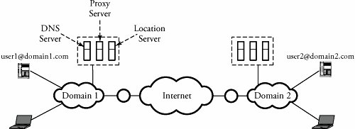
Figure 18.2 shows the placement of VoIP in the five-layer TCP/IP model. SIP, H.323, and MGCP run over TCP or UDP; real-time data transmission protocols, such as RTP, typically run over UDP. Real-time transmissions of audio and video traffic are implemented over UDP, since the real-time data requires lower delay and less overhead. Our focus in this chapter is on the two signaling protocols SIP and H.323 and on RTP and RTCP. Figure 18.2. Main protocols for VoIP and corresponding layers of operation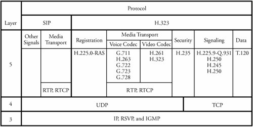 18.2.1. Session Initiation Protocol (SIP)The Session Initiation Protocol (SIP) is one of the most important VoIP signaling protocols operating in the application layer in the five-layer TCP/IP model. SIP can perform both unicast and multicast sessions and supports user mobility. SIP handles signals and identifies user location, call setup, call termination, and busy signals. SIP can use multicast to support conference calls and uses the Session Description Protocol (SDP) to negotiate parameters. SIP ComponentsFigure 18.3 shows an overview of SIP. A call is initiated from a user agent : the user's IP telephone system, which is similar to a conventional phone. A user agent assists in initiating or terminating a phone call in VoIP networks. A user agent can be implemented in a standard telephone or in a laptop with a microphone that runs some software. A user agent is identified using its associated domain. For example, user1@domain1.com refers to user 1, who is associated with the domain1.com network. Figure 18.3. Overview of SIP SIP consists of the following five servers:
Session Signaling and NumberingFigure 18.4 shows a SIP session between user agents 1 and 2: user1@domain1.com and user2@domain2.com, respectively. In this example, user 1 places a call to contact user 2. User 1 first communicates with its DNS server to map the domain name to an IP address in the SIP UID. The DNS server then communicates with the proxy server of the called party. At this point, user 1 has resolved the name of user2@domain2.com into an IP address through DNS query and response. Figure 18.4. Overview of SIP signaling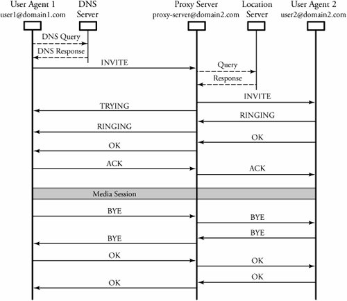 SIP uses IP addresses for numbering. Locating users in an integrated network consisting of different networks is a complex task. In addition, an optimal route to the user after the user is located must be found. The location servers use a the Telephone Routing Over IP (TRIP) protocol to locate a user in an integrated network. TRIP advertises routes, exchanges routing information, and divides the globe into IP telephone administrative domains (ITAD). Location servers exchange information about routes with signaling gateways connecting to various ITADs. The first signal to establish this call is the INVITE message, which is used for session creation. The INVITE message contains such information fields as from, to, via , and call-id , in addition to routing information. The proxy server in turn communicates with a location server of the called party. The end point of the called party, user2@domain2.com, is sent an INVITE message to initiate a session. Once user 2 receives a connection query, the TRYING signal is propagated to user 1 from the proxy server, indicating that the call is being routed. This signal is also used to keep track of the call process. A RINGING signal is transmitted from user 2 back to user 1. When user 2 accepts the call, an OK signal is issued back to user 1 to indicate that the called party has accepted the call. This last signal is acknowledged by an ACK message without any response. The called party picks up the phone, and the two IP phones communicate directly through a media session , using the real-time protocol, as shown in the figure. At the end of the conversation, the BYE message is used for a session termination, ending the call. A few other message signals can be used for other services. The CANCEL message is used to cancel a pending request. The REGISTER message is used to register the user's location. After registration, the user can be reached at a specific URL. Finally the OPTIONS message is used to learn about the parameters used by the called party. 18.2.2. H.323 ProtocolsThe H.323-series protocols are implemented in layer 5 of the TCP/IP model and run over either TCP or UDP. The H.323 protocols interact to provide ideal telephone communication, providing phone numbers to IP address mapping, handling digitized audio streaming in IP telephony, and providing signaling functions for call setup and call management. The H.323 seriies supports simultaneous voice and data transmission and can transmit binary messages that are encoded using basic encoding rules . From the security standpoint, the H.323 scheme provides a unique framework for security, user authentication, and authorization and supports conference calls and multipoint connections, as well as accounting and call-forwarding services. H.323 ComponentsFigure 18.5 shows an overview of the H.323 protocol connections. The H.323 scheme defines the following five components:
Figure 18.5. Overview of H.323 protocol connection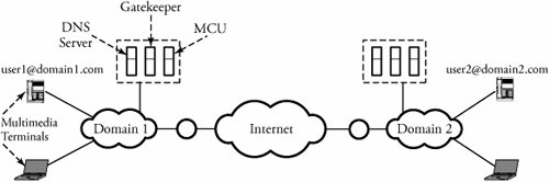 A gatekeeper can send signals to other gatekeepers of different zones to access users of those domains. This feature supports distributed locations of multinational systems. Session Signaling and NumberingFigures 18.6 and 18.7 show the details of two IP telephone communications using H.323-series protocols. Assume that two user agents 1 and 2: user1@domain1.com and user2@domain2.com, respectively. In this example, user 1 places a call to contact user 2. Figure 18.6. H.323 protocol signaling: steps 1, 2, and 3 Figure 18.7. H.323 protocol signaling: steps 4 and 5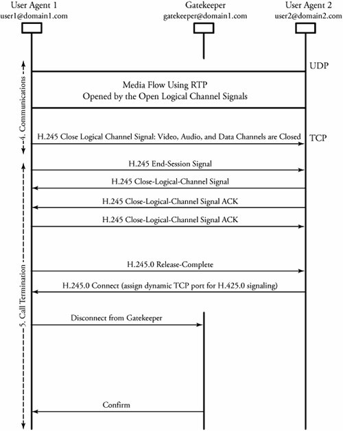 First, user 1 communicates with its DNS server, as explained earlier. The signaling uses both UDP and TCP, and partitioned into the following five steps:
At step 1, when user1 dials user 2's telephone number, the first set of signals are exchanged between these two users in conjunction with opening a TCP connection. TCP-SYN, TCP-SYN-ACK, and then TCP-ACK signals are generated between the two users. At this point, the H225.0 SETUP ON TCP signal informs the called party that the connection can be set up on TCP. The users can now request a certain bandwidth from the associated gatekeeper server of the called party. The requested bandwidth is granted if sufficient bandwidth is left over on the connection; otherwise , the call has to find another gatekeeper to register with. This phase is handled by H.225 and H.245 protocols. At step 2, all the end points' communication capabilities available over TCP are exchanged. This phase is necessary because the type of communication service requested depends on the communication capabilities of both end points. Step 3 implements the establishment of a logical channel, which in H.323 is unidirectional; therefore, a logical channel must be established in either direction in order to have two-way communications. At the end of this phase, two end points are set for communications. Meanwhile, more bandwidth can also be requested, as shown in the figure, before communications start. Step 4 comprises the communications between the two users. This phase is handled using RTP over UDP. At this step, any kind of media flow can be considered , depending on the size and type of the channel established in step 4. Finally at step 5, the call is terminated by either user. In Figure 18.7, user 2 initiates the termination of the call by closing the logical channel in H.245 and disconnecting the call from the gatekeeper. |
EAN: 2147483647
Pages: 211