Making Our Triangle Three Dimensional
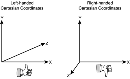
| Looking back at our application, it doesn't appear to be very three dimensional. All we did was draw a colored triangle inside a window, which could just as easily have been done with GDI. So, how do we actually draw something in 3D and have it look a little more impressive? Actually, it's relatively simple to modify our existing application to accommodate us. If you remember, earlier when we were first creating the data for our triangle, we used something called transformed coordinates. These coordinates are already known to be in screen space, and are easily defined. What if we had some coordinates that weren't already transformed though? These untransformed coordinates make up the majority of a scene in a modern 3D game. When we are defining these coordinates, we need to define each vertex in world space, rather than screen space. You can think of world space as an infinite three-dimensional Cartesian space. You can place your objects anywhere in this "world" you want to. Let's modify our application to draw an untransformed triangle now. We'll first change our triangle data to use one of the untransformed vertex format types; in this case, all we really care about is the position of our vertices, and the color, so we'll choose CustomVertex.PositionColored. Change your triangle data code to the following: CustomVertex.PositionColored[] verts = new CustomVertex.PositionColored[3]; verts[0].SetPosition(new Vector3(0.0f, 1.0f, 1.0f)); verts[0].Color = System.Drawing.Color.Aqua.ToArgb(); verts[1].SetPosition(new Vector3(-1.0f, -1.0f, 1.0f)); verts[1].Color = System.Drawing.Color.Black.ToArgb(); verts[2].SetPosition(new Vector3(1.0f, -1.0f, 1.0f)); verts[2].Color = System.Drawing.Color.Purple.ToArgb(); And change your VertexFormat property as well: device.VertexFormat = CustomVertex.PositionColored.Format; Now what's this? If you run the application, nothing happens; you're back to your colored screen, and nothing else. Before we figure out why, let's take a moment to describe the changes. As you can see, we've switched our data to use the PositionColored structure instead. This structure will hold the vertices in world space as well as the color of each vertex. Since these vertices aren't transformed, we use a Vector3 class in place of the Vector4 we used with the transformed classes, because transformed vertices do not have an rhw component. The members of the Vector3 structure map directly to the coordinates in world space; x, y, and z. We also need to make sure Direct3D knows we've changed the type of data we are drawing, so we change our fixed function pipeline to use the new untransformed and colored vertices by updating the VertexFormat property. So why isn't anything displayed when we run our application? The problem here is that while we're now drawing our vertices in world space, we haven't given Direct3D any information on how it should display them. We need to add a camera to the scene that can define how to view our vertices. In our transformed coordinates, a camera wasn't necessary because Direct3D already knew where to place the vertices in screen space. The camera is controlled via two different transforms that can be set on the device. Each transform is defined as a 4x4 matrix that you can pass in to Direct3D. The projection transform is used to define how the scene is projected onto the monitor. One of the easiest ways to generate a projection matrix is to use the PerspectiveFovLH function on the Matrix class. This will create a perspective projection matrix using the field of view, in a left-handed coordinate system. What exactly is a left-handed coordinate system anyway, and why does it matter? In most Cartesian 3D coordinate systems, positive x coordinates move toward the right, while positive y coordinates move up. The only other coordinate left is z. In a left-handed coordinate system, positive z moves away from you, while in a right-handed coordinate system, positive z moves toward you. You can easily remember which coordinate system is which by taking either hand and having your fingers point toward positive x. Then twist and curl your fingers so they are now pointing to positive y. The direction your thumb is pointing is positive z. See Figure 1.1. Figure 1.1. 3D coordinate systems.
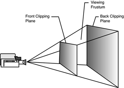
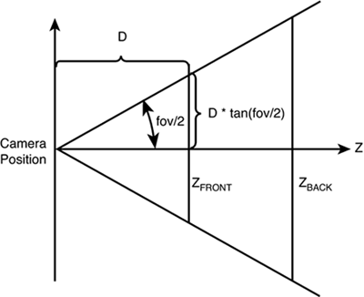
Direct3D uses a left-handed coordinate system. If you are porting code from a right-handed coordinate system, there are two things you need to do. First, flip the order of your triangles so they are ordered clockwise from front. This is done so back face culling works correctly. Don't worry; we'll get to back face culling soon. Second, use the view matrix to scale the world by 1 in the z direction. You can do this by flipping the sign of the M31, M32, M33, and M34 members of the view matrix. You can then use the RH versions of the matrix functions to build right-handed matrices. Now, since we are creating a new application, we will just use the left-handed coordinate system that Direct3D expects. Here is the prototype for our projection matrix function: public static Microsoft.DirectX.Matrix PerspectiveFovLH ( System.Single fieldOfViewY , System.Single aspectRatio , System.Single znearPlane , System.Single zfarPlane ) The projection transform is used to describe the view frustum of the scene. You can think of the view frustum as a pyramid with the top of it cut off, with the inside of said pyramid being the viewable area of your scene. The two parameters in our function, the near and far planes, describe the limits of this pyramid, with the far plane making up the "base" of the pyramid structure, while the near plane is where we cut off the top. See Figure 1.2. The field of view parameter describes the angle at the point of the pyramid. See Figure 1.3. You can think of the aspect ratio just like the aspect ratio of your television; for example, a wide screen television has an aspect ratio of 1.85. You can normally figure this parameter out easily by dividing the width of your viewing area by the height. Only objects that are contained within this frustum are drawn by Direct3D. Figure 1.2. Visualizing the viewing frustum.
Figure 1.3. Determining field of view.
Since we never set our projection transform, our view frustum never really existed, thus there was nothing really for Direct3D to draw. However, even if we did create our projection transform, we never created our view transform, which contains the information about the camera itself. We can easily do this with the look at function. The prototype for this function follows: public static Microsoft.DirectX.Matrix LookAtLH(Microsoft.DirectX.Vector3 cameraPosition, Microsoft.DirectX.Vector3 cameraTarget , Microsoft.DirectX.Vector3 cameraUpVector ) This function is pretty self-explanatory. It takes three arguments that describe the properties of the camera. The first argument is the camera's position in world space. The next argument is the position in world space we want the camera to look at. The last argument is the direction that will be considered "up." With the description of the projection transform and the view transform, Direct3D would now have enough information to display our newly drawn triangle, so let's go ahead and modify our code to get something displayed. We'll add a new function, "SetupCamera", into our OnPaint function just after our clear call. The body of this function will be private void SetupCamera() { device.Transform.Projection = Matrix.PerspectiveFovLH((float)Math.PI / 4, this.Width / this.Height, 1.0f, 100.0f); device.Transform.View = Matrix.LookAtLH(new Vector3(0,0, 5.0f), new Vector3(), new Vector3(0,1,0)); } As you can see, we create our projection matrix and set that to our device's projection transform to let Direct3D know what our view frustum is. We then create our view matrix and set that to our device's view transform so Direct3D knows our camera information. Add a call to this function into OnPaint directly after the clear call, and we are now ready to run our application once more. That doesn't seem right. Sure, we've got our triangle drawn now, but it's all black, even though we just specified which colors we wanted the triangle points to be. Once again, the problem lies in the difference between the pretransformed triangle we drew in our first application, and our nontransformed triangle now. In a nontransformed environment, by default Direct3D uses lighting to determine the final pixel color of each primitive in the scene. Since we have no lights defined in our scene, there is no external light shining on our triangle, so it appears black. We've already defined the color we want our triangle to appear, so for now, it's safe to simply turn off the lights in the scene. You can accomplish this easily by adding the following line to the end of your SetupCamera function call: device.RenderState.Lighting = false; Running the application now will show a triangle similar to our first pretransformed triangle. It seems we've done a lot of work to get back into the same position we were before we switched to our nontransformed triangles. What real benefit did we get from making these changes? Well, the major one is that we've got our triangle in a real three-dimensional world now, rather than just drawing them in screen coordinates. This is the first step in creating compelling 3D content.
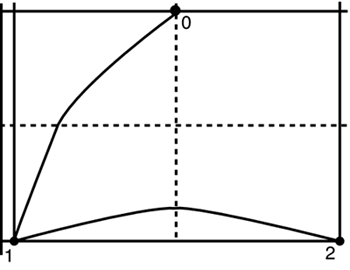
So now that we've got our triangle drawn in our world, what could we do that would make it actually look like a three-dimensional world? Well, the easiest thing we could do would be to just rotate the triangle. So, how can you go about doing this? Luckily, it's quite simple; we simply have to modify the world transform. The world transform on the device is used to transform the objects being drawn from model space, which is where each vertex is defined with respect to the model, to world space, where each vertex is actually placed in the world. The world transform can be any combination of translations (movements), rotations, and scales. Since we only want to rotate our triangle right now, we'll just create a single transform for this. There are many functions off the Matrix object that can be used to create these transforms. Add the following line to your SetupCamera function: device.Transform.World = Matrix.RotationZ((float)Math.PI / 6.0f); This tells Direct3D that the transform for each object drawn after this should use the following world transform, at least until a new world transform is specified. The world transform is created by rotating our objects on the z axis, and we pass in an angle to the function. The angle should be specified in radians, not degrees. There is a helper function, "Geometry.DegreeToRadians", in the Direct3DX library (which we'll add to our project later). We just picked this angle arbitrarily to show the effect. Running this application shows you the same triangle as before, but now rotated about its z axis. Fancy, but still a little bland; let's spice it up by making the rotation happen continuously. Let's modify the world transform: device.Transform.World = Matrix.RotationZ((System.Environment.TickCount / 450.0f) / (float)Math.PI); Running our project now should show our triangle spinning around slowly about the z axis. It seems a little jumpy, but that is caused by the TickCount property. The TickCount property in the System class is a small wrapper on the GetTickCount method in the Win32 API, which has a resolution of approximately 15 milliseconds. This means that the number returned here will only update in increments of approximately 15, which causes this jumpy behavior. We can smooth out the rotation easily by having our own counter being incremented, rather than using TickCount. Add a new member variable called "angle" of type float. Then change your world transform as follows: device.Transform.World = Matrix.RotationZ(angle / (float)Math.PI); angle += 0.1f; Now the triangle rotates smoothly around. Controlling rotation (or any movement) in this way is not a recommended tactic, since the variable is incremented based on the speed of the rendering code. With the rapid speed increases of modern computers, basing your rendering code on variables like this can cause your application to run entirely too fast on newer hardware, or even worse, entirely too slow on old hardware. We will discuss a better way to base your code on a much higher resolution timer later in the book. Our spinning triangle still isn't all that impressive, though. Let's try to be real fancy and make our object spin on multiple axes at once. Luckily, we have just the function for that. Update our world transform like the following: device.Transform.World = Matrix.RotationAxis(new Vector3(angle / ((float)Math.PI * 2.0f), angle / ((float)Math.PI * 4.0f), angle / ((float)Math.PI * 6.0f)), angle / (float)Math.PI); The major difference between this line of code and the last is the new function we are calling, namely RotationAxis. In this call, we first define the axis we want to rotate around, and we will define our axis much like we do the angle, with a simple math formula for each component of the axis. We then use the same formula for the rotation angle. Go ahead and run this new application so we can see the results of our rotating triangle. Oh no! Now our triangle starts to spin around, disappears momentarily, and then reappears, and continues this pattern forever. Remember earlier when back face culling was mentioned? Well, this is the perfect example of what back face culling really does. When Direct3D is rendering the triangles, if it determines that a particular face is not facing the camera, it is not drawn. This process is called back face culling. So how exactly does the runtime know if a particular primitive is facing the camera or not? A quick look at the culling options in Direct3D gives a good hint. The three culling options are none, clockwise, and counterclockwise. In the case of the clockwise or counterclockwise options, primitives whose vertices are wound in the opposite order of the cull mode are not drawn. Looking at our triangle, you can see that the vertices are wound in a counterclockwise manner. See Figure 1.4. Naturally, we picked this order for our triangle because the counterclockwise cull mode is the default for Direct3D. You could easily see the difference in how the vertices are rendered by swapping the first and third index in our vertex list. Figure 1.4. Vertex winding order.
Now that we know how back face culling works, it's obvious that for our simple application, we simply don't want or need these objects to be culled at all. There is a simple render state that controls the culling mode. Add the following line to our SetupCamera function call: device.RenderState.CullMode = Cull.None; Now, when the application is run, everything works as we would have expected. Our triangle rotates around on the screen, and it does not disappear as it rotates. For the first time, our application actually looks like something in real 3D. Before we continue, though, go ahead and resize the window a little bit. Notice how the triangle behaves the same way, and looks the same regardless of window size? |
EAN: N/A
Pages: 180
- Chapter VII Objective and Perceived Complexity and Their Impacts on Internet Communication
- Chapter X Converting Browsers to Buyers: Key Considerations in Designing Business-to-Consumer Web Sites
- Chapter XI User Satisfaction with Web Portals: An Empirical Study
- Chapter XII Web Design and E-Commerce
- Chapter XVI Turning Web Surfers into Loyal Customers: Cognitive Lock-In Through Interface Design and Web Site Usability


