6.5 100BaseT2
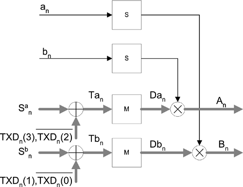
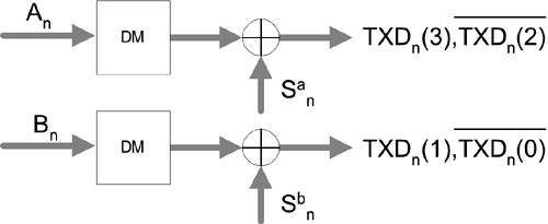
| 100BaseT2 is the latest member of the 100BaseT 100-Mbps Ethernet group. The 100BaseT2 IEEE activity was established in March 1995, and the standard was approved in March 1997. 100BaseT2 is the only Ethernet standard that supports a 100-Mbps transmission rate over two pairs of Category 3 twisted pair cabling. If the cable has more than two twisted pairs, it also permits the additional pairs to carry other services such as digital phone, 10BaseT, or more 100BaseT2 connections. Extensive digital signal processing techniques, such as fractionally spaced adaptive channel equalization, echo cancellation, and NEXT noise cancellation, are utilized to enable a very high transmission throughput over this voice-grade Category 3 twisted pair cable. 100BaseT2 employs a "dual duplex baseband transmission" scheme to transmit data over each wire pair in each direction simultaneously. In a 100BaseTX and 100BaseT4 tradition of utilizing zero voltage as a possible signal level, 100BaseT2 transmits quinary (five-level) data symbols that can have values of 2, 1, 0, +1, or +2 on each twisted pair. Each quinary symbol carries only two bits. In comparison with a four-level signaling system of the same level separation value, the use of quinary symbols has an energy penalty of 5/6 in return for some coding redundancy. In fact, each pair of two bits is first mapped to only four signal levels: +1, 0, 1, and 2. The +2 signal level is produced through the sign reverse operation under the control of a binary pseudo-random sequence. Therefore, the probability of occurrence for +2 and 2 is only half that for +1, 0, and 1 signal levels. With two pairs each carrying five signal levels, a joint constellation of 5 by 5 is created for carrying four information bits during each symbol time interval. The 100-Mbps transmission throughput is achieved with a symbol rate of 25 MHz. Full duplex operation is made possible by echo cancellation technology. On the other hand, the same cancellation technology is also applied to reduce the amount of NEXT noise level. In general, the operation of channel equalizer is synchronized to the received signal while the echo and NEXT cancellation operations are in synchronization with the clock frequency of the transmitting data. For implementation simplicity, the same timing clock is used by both transmitter and receiver parts of a transceiver. Only one transceiver, the master, can be synchronized to the clock frequency of transmitting data. The slave transceiver recovers its clock from the received signal. This arrangement is also called loop timing. 6.5.1 Summary of 100BaseT2 Ethernet StandardsThe data bit to line voltage encoding method of 100BaseT2 seems very complicated, but it can be analyzed by looking into the basic bit mapping/scrambling process and the pseudo-random sequence generator separately. Figure 6.61 shows the basic structure for bit mapping and bit/sign scrambling. Current data bits, one nibble, are represented by TXDn(0), TXDn(1), TXDn(2), and TXDn(3). The first pair of data bits Figure 6.61. Data Encoding
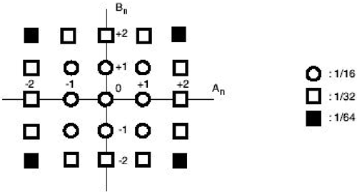
Meanwhile, the sign block S converts 0's and 1's of pseudo-random sequences of an and bn to +1's and 1's respectively. Because of this sign-scrambling process involving an, S, and the multiplier for line A, the final line signal consists of 2, 1, 0, +1, and +2 levels, while the occurrence probability of 2 or +2 level is only a half of those for 1, 0, or +1 level. The same sign-scrambling process involving bn, S, and another multiplier also applies to line B. A 5 by 5 square constellation is thus obtained with a nonuniform distribution of occurrences as shown in Figure 6.62. Figure 6.62. 100BaseT2 Constellation
All random sequences used for bit/sign scrambling are from a single pseudo-random sequence generator of length 233 1 = 8,589,934,591. The random sequence of the master transmitter is generated according to Equation 6.29
The corresponding random sequence generator can be implemented using an MLSR (Maximum Length Shift Register) structure as shown in Figure 6.63. The random sequence of the slave transmitter is generated according to Equation 6.30
Figure 6.63. Master Transmitter Random Sequence Generator (From IEEE Std. 802.3. Copyright © 2000 IEEE. All rights reserved.)
The corresponding random sequence generator can be implemented using an MLSR structure as shown in Figure 6.64. Figure 6.64. Slave Transmitter Random Sequence Generator (From IEEE Std. 802.3. Copyright © 2000 IEEE. All rights reserved.)
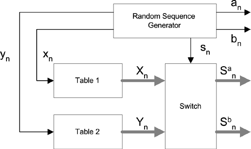
As shown in Figure 6.65, random sequences an and bn are directly from the same pseudo-random sequence generator. Specifically, we have Equation 6.31
Figure 6.65. Random Sequence Generator
and Equation 6.32
San and Sbn are a swapped version of Xn and Yn. San equals Xn and Sbn equals Ynwhen sn is 1, and San equals Yn and Sbn equals Xn when sn is 0. sn itself is the current output of the the same pseudo-random sequence generator (i.e., sn = s[n]). Values of Xn and Yn are dependent on random sequences of xn and yn as well as the odd/even sequence index according to Tables 6.5 and 6.6. The values in Table 6.5 apply when the local receiver is ready. Only values defined for the even index are used otherwise. The values in Table 6.6 apply all the time despite the readiness of the receiver. xn and yn are also obtained from the same pseudo-random sequence generator according to Equation 6.33
Equation 6.34
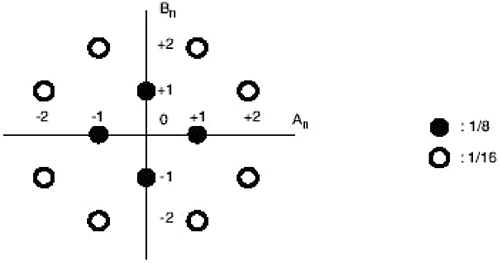
If mapped directly without Exclusive OR operations with data bits, TXDn(0), TXDn(1), TXDn(2), TXDn(3), and Xn generate signal levels of 1 and +1, and Yn generates signal levels of 0 and 2. This characteristic leads to the interesting idle constellation shown in Figure 6.66 when data bits are all zeros and with the additional help of random swapping between Xn and Yn according to the value of sn. Between data and idle transmissions, the beginning of a data stream is marked by the Start-of-Stream Delimiter, and the end of a data stream is marked by the End-of-Stream Delimiter. Both SSD and ESD last two symbols and consist of line levels of An = ±2, Bn = ±2, An+1 = ±2, and Bn+1 = 0. Figure 6.66. 100BaseT2 Idle Constellation
The pseudo-random sequence generator at the receiver side needs to be synchronized to that of the transmitter side before correct descrambling of data bits can be performed. During the initialization process, s(n) can be directly observed by examining the alternation of subsets { 1, +1} and { 2, 0, +2} of the idle constellation while an = s(n - 1) Figure 6.67. Demapping and Descrambling of Data Bits
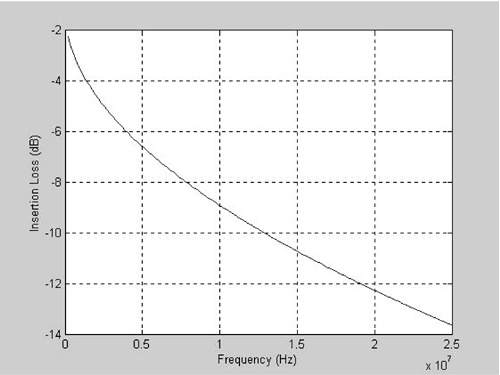
The Category 3 twisted pair cable channel model defined by the 100BaseT2 standards is given in the frequency domain by Equation 6.35
Equation 6.36
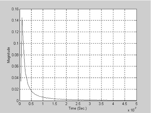
l is the length of the cable measured in meters, and f is the frequency measured in Hertz. Figure 6.68 shows this model in the frequency domain. Figure 6.69 shows this model in the time domain. Notice that the net transmission time delay is not included in this Category 3 cable model. The transmission delay is about 570 ns for 100 m of Category 3 cable. Figure 6.68. 100-Meter Category 3 Twisted Pair Cable Transfer Function
Figure 6.69. Corresponding Impulse Response
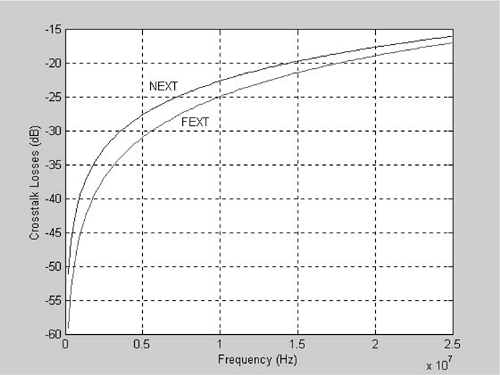
NEXT coupling loss for the 100BaseT2 transmission environment is defined for a single disturber by an attenuation of 19.3 dB at 16 MHz and a slope of 16.6 dB/decade as shown in Equation 6.37
NEXT coupling loss for multiple disturbers is also defined by an attenuation of 19 dB at 16 MHz and a slope of 16.6 dB/decade as shown in Equation 6.38
Assuming the effect of NEXT can be minimized using the digital cancellation technique, the FEXT noise will then dominate the performance of a 100BaseT2 transmission system. Since the transmitted data sequence is not readily available at the receiver end, the FEXT cancellation is not as easy to implement and not recommended in the 100BaseT2 standards. FEXT coupling loss for a 100-m Category 3 twisted pair cable is defined for a single disturber by an attenuation of 20.9 dB at 16 MHz and a slope of 20 dB/decade as shown in Equation 6.39
FEXT coupling loss for multiple disturbers is also defined by an attenuation of 19.9 dB at 16 MHz and a slope of 20 dB/decade as shown in Equation 6.40
Figure 6.70 shows corresponding NEXT and FEXT models. Figure 6.70. 100-Meter Category 3 Twisted Pair NEXT and FEXT Coupling Losses
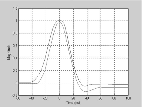
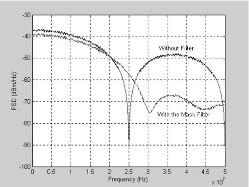
According to the 100BaseT2 standards, the peak voltage corresponding to the +2 signal level should be at around 1.8 V, and a normalized single nonzero symbol should be within the mask limits as shown in Figure 6.71. Figure 6.72 shows corresponding PSDs without using any transmitter filter and with a FIR digital filter whose coefficients are defined within the limits of the time domain mask. Figure 6.71. Time Domain Mask
Figure 6.72. Frequency Domain Template
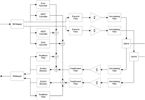
The 100BaseT2 standards specify that the same two pairs of a four-pair Category 3 cable should be connected for transmission as those defined for 10BaseT. In other words, one pair is connected to pins 1 and 2 and the other pair is connected to pins 3 and 6 of an RJ45 connector for a conventional NIC card. During autonegotiation, the transmit is connected to the pair of pins 1 and 2 and the receive is connected to the pair of pins 3 and 6. Similar rules of 10BaseT for crossover cable and hub side connection also apply. 6.5.2 Performance Estimation for 100BaseT2A possible 100BaseT2 transceiver structure is shown in Figure 6.73. The transmit path shown in the top part of Figure 6.73 consists of a pair of similar circuits of transmit filter, D/A, and anti-aliasing filters. A pair of echo/NEXT cancellers are connected in between the transmit and receive paths. For the receive path, a pair of similar circuits is there for the receive filter, A/D, channel equalizer, and symbol decision. The echo canceller, NEXT canceller, and channel equalizer are all adaptive filters whose coefficients are identified during the initialization process and updated continuously during normal operation. Echo cancellers, NEXT cancellers, and feedback filters can operate at the symbol rate of 25 MHz, while feedforward filters need to operate at a higher rate, two to three times the symbol rate, to gain some noise suppression capabilities. The bit mapper contains the pseudo-random sequence generator, bit/sign scrambling, and signal-level mapping functions. The demapper contains a synchronized pseudo-random sequence generator, bit/sign descrambling, and bit mapping functions. Figure 6.73. 100BaseT2 Transceiver Block Diagram
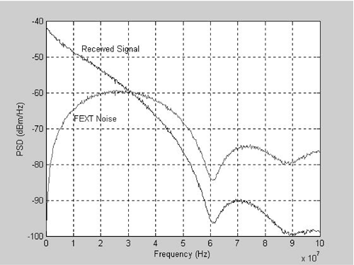
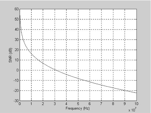
The theoretical performance of a 100BaseT2 transceiver under the worst-case noise environment as defined by the standards can be analyzed by comparing the SNR at the front of the receiver. Because of the use of NEXT cancellers, the worst-case performance environment is dominated by the FEXT noise. Figure 6.74 shows receiver front-end signal and crosstalk PSDs for a frequency band of 0 50 MHz. The 100-m Category 3 channel model and the single pair FEXT model are used to generate these PSDs, respectively. The corresponding SNR is shown in Figure 6.75. Based on these receiver front-end SNRs, the channel capacity for the 100BaseT2 transmission environment is found using Equation 6.41
Figure 6.74. Received Signal and Noise PSDs
Figure 6.75. Receiver Front-End SNR
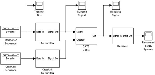
At about 156 Mbps, the channel capacity is about three times the throughput of the 100BaseT2 transmission protocol because each pair carries half of the traffic. Computer simulation can be used to study the performance of a typical 100BaseT2 transmission system under different channel and noise environments. Figure 6.76 shows a 100BaseT2 Simulink model block diagram representing one of two pairs at its highest hierarchical level. This Simulink model consists of a random binary sequence generator as the signal source, a 100BaseT2 transmitter to convert the information sequence into a five-level line voltage, another binary random sequence generator as the FEXT source, another transmitter to convert the binary sequence to crosstalk noise, a Category 3 twisted pair cable channel, and a 100BaseT2 receiver. Four scopes are placed right after the information sequence, the transmitter, the channel, and the receiver to collect simulation results. Figure 6.76. 100BaseT2 Simulink Model
Figure 6.77 shows the internal structure of the Simulink model transmitter consisting of a binary to four-level mapper, a sign scrambling function using a random sequence generator, a unit negative gain, a switch, a transmit filter function with an interpolation filter, a FIR filter, and a third-order Butterworth low-pass antialiasing filter. Figure 6.77. Transmitter Model
Figure 6.78 shows the internal structure of the bit to four-level mapper. The input to the mapper is the binary data stream, and the output is the four-level, 2, 1, 0, and 1, line signal. The buffer converts the data stream to 2-bit wide and the lookup table generates the line signal. Figure 6.78. Bit-to-Line-Signal Mapper
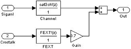
Figure 6.79 shows the Category 3 channel model consisting of a digital transfer function for the cable insertion loss, a digital transfer function for the FEXT crosstalk noise coupling loss, and an additional FEXT attenuation. The insertion loss block uses time domain channel impulse responses as defined in the standards, which are MATLAB variables preloaded at the activation of this Simulink simulation. The FEXT time domain impulse response of the standards is used for the FEXT crosstalk model with the adjustment of additional 3-dB loss by the FEXT attenuator. Only the effect of FEXT is considered because the NEXT is virtually removed by adaptive cancellation circuits. Figure 6.79. Channel Model
Figure 6.80 shows the internal structure of the Simulink model receiver consisting of a down sampling filter, an adaptive decision feedback channel equalizer, a five-level decision device, and a data bit demapper. For simplicity, the echo and NEXT cancellation circuits are not included in this simulation model. They can be constructed using adaptive filters. Figure 6.80. Receiver Model
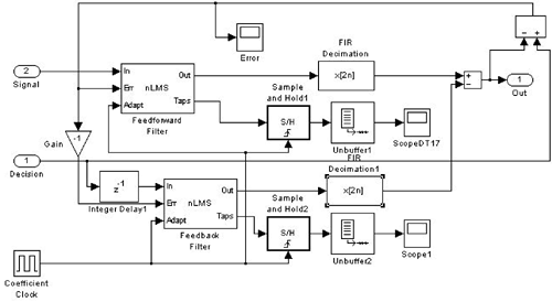
Figure 6.81 shows the internal structure of the adaptive equalizer consisting of a fractionally spaced feedforward filter and a baud rate feedback filter. The feedforward filter takes the input at twice the baud rate while updating its coefficients at the baud rate. Two down-sampling filters are used to combine the feedforward and feedback filters. In a practical system, coefficients of these two filters are identified based on the idle constellation using the blind adaptation technique during the initialization period. Some good initial values are used for this simulation model to ensure a proper convergence under the data constellation. Figure 6.81. Adaptive Equalizer
Figure 6.82 shows the internal structure of the demapper model. The decoder simply generates 1 if two consecutive inputs are not equal and 0 otherwise. The sign descrambling function consists of a random sequence generator, a delay element, a unit negative gain, and a switch. The descrambled signal level is used to drive a two-dimensional lookup table for recovering the data bit stream. Figure 6.82. Bit Demapper
|
EAN: 2147483647
Pages: 97
