6.6 Autonegotiation
| We have looked at four versions 10BaseT, 100BaseT4, 100BaseTX, and 100BaseT2 of twisted pair based Ethernet transmission systems all using the same RJ-45 connector. Although each system has its own unique physical layer and different physical layers do not communicate with each other, it will be very beneficial for a pair of Ethernet transceivers to at least recognize each other and to find out the optimal common physical layer with which they can communicate when they are connected. Because the 10BaseT transmission system requires the simplest transceiver circuits, an autonegotiation procedure has been defined in the Ethernet standards based on its link integrity test pulse sequence, and no packet or upper layer protocol overhead is required. The autonegotiation function allows Ethernet transceivers at both ends of a link segment to advertise abilities, to acknowledge receipt and understanding of common modes of operation that both devices share, and to reject the use of operational modes that are not shared. Where more than one common mode exists between the two devices, a Priority Resolution function is provided to allow the devices to resolve to a single mode of operation. The autonegotiation function also provides a Parallel Detection function to allow an Ethernet transceiver to be recognized properly in case it may not have the autonegotiation capability. The Priority Resolution function includes Table 6.7, which represents the relative priorities of different twisted pair based Ethernet transmission systems, where the system in the higher row poses the higher priority. The rationale for this hierarchy is straightforward. 10BaseT is the lowest common denominator and therefore has the lowest priority. Full-duplex solutions are always higher in priority than their half-duplex counterparts. 100BaseT2 is ahead of 100BaseTX and 100BaseT4 because 100BaseT2 runs across a broader spectrum of copper cabling and requires only two pairs. 100BaseT4 is ahead of 100BaseTX because 100BASET4 runs across a broader spectrum of copper cabling. It should be noticed that the 1000BaseT transmission system, although not examined here because it will probably not be used in homes in the near future, has a higher priority than 100-Mbps technologies.
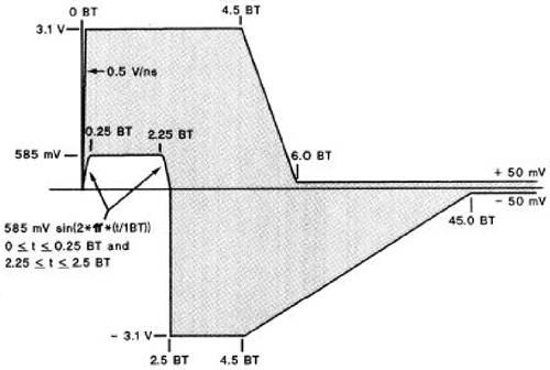
The Parallel Detection function allows detection of Ethernet transceivers that support 100BaseT4 and 100BaseTX but do not support the autonegotiation procedure. Prior to detection of the autonegotiation capability, the transceiver performs receive link integrity tests of corresponding Ethernet transmission systems. The detected transmission system capability information is incorporated into the following autonegotiation process. The Parallel Detection of the 10BaseT transmission system is not required because it will be detected during the autonegotiation procedure. The Parallel Detection of the 100BaseT2 transmission system is also not specified in the standards. When selecting the highest common denominator through the Parallel Detection function, only the half-duplex mode corresponding to the selected physical layer may automatically be detected. 6.6.1 Link Test PulseFor the original coaxial cable based Ethernet, the transmission medium is completely silent when there are no data packets to be transmitted from one transceiver to the other. For 10BaseT and 100BaseT4 twisted pair based Ethernet, the medium is almost silent during the data idle state except for some test pulses. Whenever 10BaseT is in the data idle state, a TP_IDL pulse is transmitted after a period of silence, which is followed by a repeating sequence of a 16 ± 8-ms period of silence and a link test pulse. TP-IDL and link test pulses are defined in the time domain by mask templates as shown in Figures 6.83 and 6.84, respectively. The 10BaseT link pulse activity is also referred to as the Normal Link Pulse (NLP) sequence. Figure 6.83. TP_IDL Pulse Template (From IEEE Std. 802.3. Copyright © 2000 IEEE. All rights reserved.)
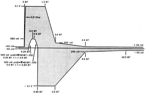
Figure 6.84. Link Test Pulse Template (From IEEE Std. 802.3. Copyright © 2000 IEEE. All rights reserved.)
The 100BaseT4 idle signal is similar to the 10BaseT idle signal, but with 100BaseT4 ternary signal levels and a faster repetition rate. The 100BaseT4 idle signal is called TP_IDL_100. The TP_IDL_100 signal is a repeating sequence formed from one 1.2 ± 0.6-ms period of silence and one link test pulse. Each link test pulse is a succession of two ternary symbols having logical values of 1 and 1. 6.6.2 Fast Link PulseAutonegotiation's method of communication builds upon the link pulse mechanism employed by 10BaseT to detect the status of the link. A 10BaseT transceiver transmits link integrity test pulses as a mechanism to determine if the link segment is operational in the absence of packet data. Autonegotiation substitutes the Fast Link Pulse (FLP) burst for the single 10BaseT link integrity test pulse within the NLP sequence as shown in Figure 6.85. The FLP burst encodes the data that is used to perform the autonegotiation function. Figure 6.85. FLP and NLP mapping (From IEEE Std. 802.3. Copyright © 2000 IEEE. All rights reserved.)
The first pulse in an FLP burst is always a clock pulse. Clock pulses within an FLP burst are spaced at 125 ± 14 µs. A logic one is represented by a pulse occurring 62.5 ± 7 µs after the preceding clock pulse. A logic zero is represented by a mission pulse within two adjacent clock pulses at least 111 µs apart as shown in Figure 6.86. Each clock or data pulse lasts 100 ns. Each FLP burst lasts 2 ms, and FLP bursts are scheduled 16 ms apart just like those of NLPs. Figure 6.86. FLP Encoding (From IEEE Std. 802.3. Copyright © 2000 IEEE. All rights reserved.)
In each FLP burst, 16 bits of data can be encoded. Among these bits, the first 5 bits belong to the selector field, and the next 8 bits belong to the technology ability field for the Base Link Code Word or Base Page as shown in Figure 6.87. The selector field code is used to identify the type of standards and the code for 802.3 Ethernet is 00001. The technology field encoding for the 802.3 selector is shown in Figure 6.88. Figure 6.87. Base Page Encoding (From IEEE Std. 802.3. Copyright © 2000 IEEE. All rights reserved.)
Figure 6.88. Technology Field Encoding for Ethernet (From IEEE Std. 802.3. Copyright © 2000 IEEE. All rights reserved.)
The 14th bit, D13, of the Base Page is used for Remote Fault (RF) indication. The 15th bit, D14, is an acknowledgment (Ack) to indicate that a device has successfully received its Link Partner's Link Code Word. The 16th bit, D15, is used for Next Page (NP). The NP is set to one if a transceiver is willing to exchange a Next Page. The Next Page can have either a Message Page or an Unformated Page encoding. The Message Page Encoding is shown in Figure 6.89. These first 11 bits of a message page belong to the Message Code Field. The message code indicating the 100BaseT2 capability is 11100000000 starting with bit M0. In the message page, bit D11, Toggle (T) is used by the arbitration function to ensure synchronization with the transceiver at the other end during Next Page exchange. This bit shall always take the opposite value of the Toggle bit in the previously exchanged page. The initial value of the Toggle bit in the first Next Page transmitted is the inverse of bit 11 of the base page. Bit D12, Acknowledge 2 (Ack2), is used by the Next Page function to indicate that a device has the ability to comply with the message. Bit D13, Message Page (MP), is used by the Next Page function to differentiate a Message Page from an Unformated Page. MP is set to one for a message page. Bit D14, Ack, is defined the same as for the Base Page. Bit D15, Next Page (NP), is used by the Next Page function to indicate whether or not this is the last Next Page to be transmitted. NP is set to zero if this is the last page. Figure 6.89. Message Page Encoding (From IEEE Std. 802.3. Copyright © 2000 IEEE. All rights reserved.)
A transceiver can set its Ack bit to one after it receives three consecutive and consistent FLP bursts from the other end. The arbitration function of the transceiver can then compare its own capabilities with those at the other end and determine the transmission method for both ends according to the same priority resolution procedure. Initialization for that particular transmission method can proceed to establish the communication link. The Parallel Detection function should have already identified the transmission method of the transceiver at the other end, if FLP bursts are not received, and the transceiver can therefore start an initialization procedure. |
EAN: 2147483647
Pages: 97