Scenario 10-6: Capturing Traffic Using SPAN, RSPAN, and VACLs
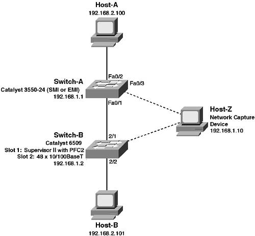
| The ability to capture traffic on the network is a fundamental requirement for any network engineer that requires low-level protocol monitoring and troubleshooting capabilities. Traditionally, in hub-based LAN environments, traffic capture has been an easy process; by simply attaching to the shared LAN segment, all traffic is seen by a monitoring device. In the modern era of the LAN switch however, Ethernet segments are no longer shared. Instead, Layer 2 unicast traffic between devices is isolated to the ports to which each device is connected, meaning a monitoring device connected to another port has no visibility of traffic. To enable the ability to capture traffic sent and received on other switch ports, Cisco Catalyst switches include a feature called the switch port analyzer feature (SPAN), as well as remote SPAN (RSPAN) and VLAN access control lists (VACLs). In this scenario you learn how to capture traffic using the SPAN, RSPAN, and VACLs. SPAN, RSPAN, and VACLs are all techniques that have been developed that enable administrators to troubleshoot and monitor LAN communications in a switched environment. This capability is a very important troubleshooting and monitoring tool when verifying the data communications between devices in your LAN network. Figure 10-10 illustrates the topology used for this scenario. Figure 10-10. Scenario 10-6 Topology
In this scenario you learn how to use SPAN and VLAN access control lists to monitor traffic on a single switch and learn how to use RSPAN to monitor traffic across multiple switches. To generate traffic and to verify that the traffic capturing features are working correctly, you need two hosts that simulate LAN communications, as well as another host that has some form of network capture software. Understanding Traffic CaptureThe ability to capture traffic on any network is important for both troubleshooting and monitoring purposes. In traditional shared hub environments, capturing traffic from the local LAN is not a problem because all traffic is seen by all devices attached to the shared media. In switched networks, however, this does not happen because a switch only forwards unicast traffic out the port attached to the destination and not to any other ports. To monitor traffic in a switched network, Cisco Catalyst switches provide three features:
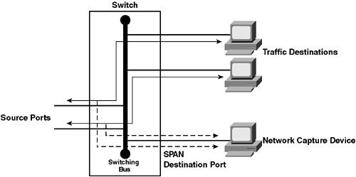
SPANSPAN is the traditional method of monitoring LAN traffic on Cisco switches. SPAN uses the concept of mirroring traffic from a set of source ports to a single destination port, which has a network capture tool connected to it. Figure 10-11 demonstrates SPAN operation. Figure 10-11. SPAN Operation
In Figure 10-11, the traffic received on a group of source ports is mirrored out a single destination port to some form of network capture device. Figure 10-11 represents a SPAN session, which is essentially a relationship between a set of source ports and a single, unique destination port. With SPAN, only a single destination port can be configured, while multiple source ports can be configured per session. Looking at source ports, you can configure a SPAN session to mirror traffic either received, transmitted, or both transmitted and received on the source ports. You can also specify a VLAN as a source, which means that the Catalyst switch automatically mirrors the traffic from all ports in the VLAN to the destination port. This feature is sometimes referred to as VLAN SPAN or VSPAN. Depending on the direction of traffic that is mirrored, a SPAN session can be defined as one of the following session types:
Differentiating between ingress and egress SPAN sessions is important because some Catalyst switches have different limitations as to the maximum number of ingress and egress SPAN sessions that you can run. While SPAN meets the requirements of many traffic capture environments, it does have a few limitations of which you need to be aware:
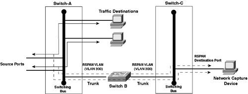
RSPANOne useful feature of SPAN is an extension of SPAN called remote SPAN or RSPAN. RSPAN allows you to monitor traffic from source ports distributed over multiple switches, which means that you can centralize your network capture devices. RSPAN works by mirroring the traffic from the source ports of an RSPAN session onto a VLAN that is dedicated for the RSPAN session. This VLAN is then trunked to other switches, allowing the RSPAN session traffic to be transported across multiple switches. On the switch that contains the destination port for the session, traffic from the RSPAN session VLAN is simply mirrored out the destination port. Figure 10-12 demonstrates RSPAN operation. Figure 10-12. RSPAN Operation
In Figure 10-12, Switch-A hosts the source ports of an RSPAN session and is configured to mirror all traffic received on these ports to VLAN 300, which is a special VLAN created for the RSPAN session. The mirrored traffic is tagged with a VLAN ID of 300 and then forwarded across the trunk to Switch-B, which simply forwards the tagged traffic across the trunk to Switch-C. Switch-C is configured to mirror all traffic received on the RSPAN VLAN (VLAN 300) to the destination port, enabling the network capture device to monitor ports on a remote switch. Because an RSPAN session spans many switches, various types of RSPAN components comprise an overall RSPAN session. An RSPAN session actually consists of three different components:
A major requirement for RSPAN to work is that all switches with RSPAN source and RSPAN destination sessions, as well as any transit switch that transports RSPAN traffic, must support RSPAN. Understanding the different types of RSPAN components is important, because there are limitations as to the number of RSPAN source and destination sessions you can configure on a switch. Table 10-2 describes the platforms that currently support RSPAN.
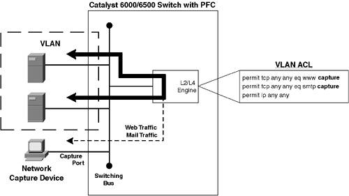
VACLsVACLs are a feature supported on the Catalyst 6000/6500 that was discussed in Chapter 8 in the context of network security. Although VACLs are primarily used for providing network access control at Layer 3/4 between devices attached to the same VLAN, they can also be used to capture traffic that is subsequently mirrored to a list of capture ports. Figure 10-13 demonstrates VACL operation. Figure 10-13. VACL Operation
In Figure 10-13, a VACL is applied to the VLAN shown. This means that all traffic within the VLAN is passed through the VACL by the L2/L4 engine (on the Supervisor 2 with PFC-2) or on the ACL engine (with the Supervisor 1 with PFC-2). Notice that the VACL specifies the capture keyword at the end of the access control entries (ACEs) that match web and mail traffic. Any traffic that matches an ACE that specifies the capture keyword is mirrored to a list of capture ports. In Figure 10-13, the bottom port is a member of the capture port list and thus receives World Wide Web and SMTP traffic on the VLAN shown. The following describes the advantages of using VACLs to capture traffic:
The only real restriction of using VACLs to capture traffic is that it is supported only on the Catalyst 6000/6500 with a policy feature card (PFC) installed. If you are using another platform, or do not have a PFC installed, you must use SPAN to capture traffic. TIP You can use VACLs (without the capture keyword) to filter traffic on an RSPAN session VLAN, allowing you to effectively control the traffic at a Layer 3/4 level that is mirrored out the destination port in the RSPAN session. You simply would create a VACL that explicitly permits the traffic that you want mirrored and drops all other traffic. Such a technique is most effective when applied on the switch that contains the source ports of the RSPAN session. SPAN and RSPAN Session LimitationsBefore learning how to configure SPAN and RSPAN, it is important to understand that Cisco Catalyst switches have limitations as to the number of SPAN and RSPAN sessions that are supported running at the same time. Table 10-3 lists the SPAN and RSPAN session limitations of the various Cisco Catalyst switch platforms.
NOTE Transit switches for an RSPAN session (e.g., Switch-B in Figure 10-12), where traffic for the session is transported via an RSPAN VLAN but no source or destination ports for the RSPAN session are configured on the transit switch, do not have a limitation as to the number of RSPAN sessions that can transit the switch. Transit switches must support RSPAN, however, because RSPAN VLANs have special properties not understood by switches that do no support RSPAN. Scenario PrerequisitesTo successfully commence the configuration tasks required to complete this scenario, Table 10-4 describes the prerequisite configurations required on each device in the scenario topology. Any configurations not listed can be assumed as being the default configuration.
Example 10-79 and Example 10-80 shows the prerequisite configuration required on Switch-A and Switch-B respectively. Example 10-79. Scenario 10-6 Prerequisite Configuration for Switch-ASwitch# configure terminal Switch(config)# hostname Switch-A Switch-A(config)# enable secret cisco Switch-A(config)# line vty 0 15 Switch-A(config-line)# password cisco Switch-A(config-line)# exit Switch-A(config)# interface vlan 1 Switch-A(config-if)# no shutdown Switch-A(config-if)# ip address 192.168.1.1 255.255.255.0 Switch-A(config-if)# exit Switch-A(config)# vtp mode transparent Setting device to VTP TRANSPARENT mode. Switch-A(config)# vlan 2 Switch-A(config-vlan)# name VLAN02 Switch-A(config-vlan)# exit Switch-A(config)# interface fastEthernet0/1 Switch-A(config-if)# switchport trunk encapsulation dot1q Switch-A(config-if)# switchport mode trunk Switch-A(config-if)# switchport nonegotiate Switch-A(config)# interface fastEthernet0/2 Switch-A(config-if)# switchport access vlan 2 Example 10-80. Scenario 10-6 Prerequisite Configuration for Switch-BConsole> (enable) set system name Switch-B System name set. Switch-B> (enable) set password Enter old password: Ø Enter new password: ***** Retype new password: ***** Password changed. Switch-B> (enable) set enablepass Enter old password: Ø Enter new password: ***** Retype new password: ***** Password changed. Switch-B> (enable) set interface sc0 192.168.1.2 255.255.255.0 Interface sc0 IP address and netmask set. Switch-B> (enable) set vtp mode transparent VTP domain modified Switch-B> (enable) set vlan 2 name VLAN02 VTP advertisements transmitting temporarily stopped, and will resume after the command finishes. Vlan 2 configuration successful Switch-B> (enable) set vlan 2 2/2 VLAN 2 modified. VLAN 1 modified. VLAN Mod/Ports ---- ----------------------- 2 2/1,2/2 Switch-B> (enable) set trunk 2/1 nonegotiate dot1q Port(s) 2/1 trunk mode set to nonegotiate. Port(s) 2/1 trunk type set to dot1q. After the prerequisite configuration is implemented, you should attach each host as indicated in Figure 10-10 and verify PING connectivity between devices where possible in before proceeding. Host-A and Host-B should be able to ping each other, whilst Host-Z should also be able to ping both Switch-A and Switch-B. Configuration TasksThis scenario demonstrates the use of SPAN, RSPAN, and VACLs to provide the capturing of traffic sent and/or received by one or more interfaces or VLANs on a Cisco Catalyst switch. This requires the following configuration tasks:
Configuring SPANIn this scenario, SPAN is configured on both Switch-A and Switch-B, to demonstrate the configuration of SPAN on Cisco IOS and CatOS. This requires the following configuration tasks:
Configuring SPAN on Cisco IOSIn this section, a continuous traffic stream in VLAN 2 between Host-A and Host-B is generated, as well as a continuous traffic stream in VLAN 1 between Switch-B and Switch-A. Switch-A is configured to mirror this traffic to Host-Z (which must be connected to interface Fa0/3 on Switch-A) using SPAN. This requires the following configuration tasks to be implemented:
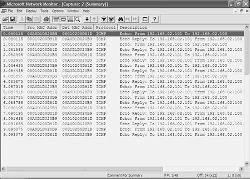
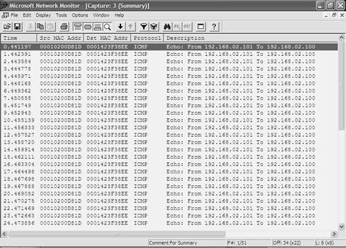
To generate traffic between Host-A and Host-B in VLAN 2, the ping utility can be used with the t option on Windows, which generates a continuous stream of ping packets. Example 10-81 demonstrates generating a continuous ping on Host-B between Host-B and Host-A. Example 10-81. Generating a Continuous Traffic Stream on VLAN 2 Between Host-B and Host-A from Host-B C:\> ping t 192.168.2.100 Pinging 192.168.2.100 with 32 bytes of data: Reply from 192.168.2.100: bytes=32 time=1ms TTL=255 Reply from 192.168.2.100: bytes=32 time=1ms TTL=255 Reply from 192.168.2.100: bytes=32 time=1ms TTL=255 Reply from 192.168.2.100: bytes=32 time=1ms TTL=255 Reply from 192.168.2.100: bytes=32 time=1ms TTL=255 ... ... In Example 10-81, the t switch is used with the Windows ping utility to continuously generate ping traffic. ICMP Echo Requests are sent from 192.168.2.101 (Host-B) to 192.168.2.100 (Host-A), with ICMP Echo Replies sent from 192.168.2.100 (Host-A) to 192.168.2.101 (Host-B). NOTE At this point, if you start capturing network traffic on Host-Z, you should notice that the traffic generated in Example 10-79 is not being captured because SPAN is not configured at present. The only traffic that should be captured is flooded unicast traffic, multicast and broadcast traffic, or unicast traffic generated locally by Host-Z. Now that a particular type of traffic is being generated in the network, SPAN can be configured to mirror that traffic to Host-Z. On Cisco IOS, the monitor session global configuration command is used to create SPAN sessions. When configuring SPAN, you must configure the source interfaces/VLANs and the destination interface separately. The following shows the syntax for configuring source interfaces and/or VLANs: Switch(config)# monitor session session-id source interface interface-type interface-id [tx | rx | both] Switch(config)# monitor session session-id source vlan vlan-id [rx] Notice that if you specify a source interface, you can capture traffic sent, received, or sent and received using the tx, rx, or both keywords respectively. If you specify a source VLAN, you can capture only traffic received by interfaces belonging to the VLAN. NOTE You can configure source interfaces and source VLANs for the same SPAN session. After configuring the source interfaces/VLANs, you must next configure the destination port. Only a single destination port can be configured, which is created using the monitor session command as follows: Switch(config)# monitor session session-id destination interface interface-type interface-id [encapsulation] {dot1q | isl | replicate}] [ingress vlan vlan-id] Notice the two optional parameters you can define along with the destination interface. The optional encapsulation command allows you to tag frames mirrored to the monitoring device with their VLAN ID, using either 802.1q (dot1q), ISL (isl), or the tagging of the original packet (replicate). The optional ingress vlan vlan-id configuration ensures that frames input on the destination SPAN port (i.e., received from the packet capture device) will be accepted and placed into the VLAN specified. In this scenario, Host-B is currently generating continuous ICMP echo requests to Host-A, with ICMP echo replies sent back from Host-A to Host-B. To capture this traffic on Switch-A, you can create a SPAN session that specifies interface fastEthernet 0/2 (attached to Host-A) as the source interface and interface fastEthernet 0/3 (attached to Host-Z) as the destination interface. Alternatively, you could configure VLAN 2 as the source VLAN, which would automatically add interface fastEthernet 0/3 as a source port given that it belongs to VLAN 2. Example 10-82 demonstrates configuring a SPAN session on Switch-A to capture traffic transmitted and received on the interface attached to Host-A. Example 10-82. Configuring a SPAN Session on Cisco IOSSwitch-A# configure terminal Switch-A(config)# monitor session 1 source interface fastEthernet0/2 both Switch-A(config)# monitor session 1 destination interface fastEthernet0/3 Switch-A(config)# exit Switch-A# show monitor Session 1 --------- Type : Local Session Source Ports : Both : Fa0/2 Destination Ports : Fa0/3 Encapsulation: Native Ingress: Disabled In Example 10-82, the first command creates a new SPAN session with an ID of 1 and defines a source interface for the SPAN session (interface Fa0/2). The second command specifies that traffic both sent and received (indicated by the both keyword) on the source interfaces should be mirrored to the destination interface. After the SPAN session is created, the show monitor command is executed to verify the SPAN configuration. At this stage, if the network capture software on Host-Z is started, Host-Z should be able to see the traffic sent between Host-A and Host-B, even though the interface attached to Host-Z is not even on the same VLAN as Host-A and Host-B. Figure 10-14 demonstrates a network capture performed on Host-Z (using Microsoft Network Monitor, which ships as a free, optional component with Windows 2000 server) after the configuration of Example 10-79 is implemented. Figure 10-14. Network Capture Output on Host-Z
In Figure 10-14, the output has actually been filtered to display only ICMP packets because any traffic between Host-A and Host-B is captured. Notice in the Description column (other columns are hidden from view), you can see each ICMP Echo packet sent from 192.168.2.101 (HostB) to 192.168.2.100 (Host-A) and the corresponding ICMP Echo Reply packet sent from Host-A to Host-B. This verifies that SPAN is working and that the SPAN session is mirroring traffic sent and received on the interface attached to Host-A. If you now try and attempt to communicate from Host-Z within VLAN 1, you should find that Host-Z is unable to communicate at all. This is easily verified by attempting to ping either Switch-A or Switch-B from Host-Z, which should fail, as demonstrated in Example 10-83. Example 10-83. Attempting Communications from Host-Z C:\> ping 192.168.1.1 Pinging 192.168.1.1 with 32 bytes of data: Request timed out. Request timed out. Request timed out. Request timed out. Ping statistics for 192.168.1.1: Packets: Sent = 4, Received = 0, Lost = 4 (100% loss), The reason why Host-Z cannot communicate is because the destination interface for the SPAN session has not been configured to enable incoming packets on the destination port (using the optional ingress keyword). Now that configuring a SPAN session with source interfaces has been demonstrated, it is time to demonstrate configuring a VSPAN session, where one or more VLANs can be configured as the source for the SPAN session. To demonstrate configuring multiple VLANs as the source, traffic needs to be generated in VLAN 1. Example 10-84 demonstrates configuring a continuous ping from Switch-B to Switch-A, which generates continuous traffic in VLAN 1. Example 10-84. Configuring a Continuous ping on Switch-B Switch-B> (enable) ping -s 192.168.1.2 PING 192.168.1.2: 56 data bytes 64 bytes from 192.168.1.2: icmp_seq=0. time=5 ms 64 bytes from 192.168.1.2: icmp_seq=1. time=1 ms 64 bytes from 192.168.1.2: icmp_seq=2. time=1 ms 64 bytes from 192.168.1.2: icmp_seq=3. time=1 ms 64 bytes from 192.168.1.2: icmp_seq=4. time=1 ms 64 bytes from 192.168.1.2: icmp_seq=5. time=1 ms 64 bytes from 192.168.1.2: icmp_seq=6. time=1 ms ... ... Example 10-85 demonstrates removing the SPAN session configured in Example 10-82 on Switch-A, creating a new SPAN session that specifies both VLAN 1 and VLAN 2 as source VLANs, and this time configuring the destination interface to Host-Z to accept incoming packets. Example 10-85. Configuring a VSPAN Session on Cisco IOS with Incoming Packets EnabledSwitch-A# configure terminal Switch-A(config)# no monitor 1 Switch-A(config)# monitor session 1 source vlan fastEthernet0/2 rx Switch-A(config)# monitor session 1 destination interface fastEthernet0/3 ingress vlan 1 Switch-A(config)# exit Switch-A# show monitor Session 1 --------- Type : Local Session Source VLANs : RX Only : 1-2 Destination Ports : Fa0/3 Encapsulation: Native Ingress: Enabled, default VLAN = 1 After removing the previous SPAN session, notice that next only traffic received on the source VLANs is mirrored to the destination port because this is the only direction supported for source VLANs on the Catalyst 3550. The destination interface configured for the SPAN session is configured to accept incoming packets and place them in VLAN 1, as indicated by the ingress vlan 1 keywords. At this stage on Host-Z, if you perform another packet capture, this time you should see ICMP traffic being generated in VLAN 1 (between Switch-A and Switch-B), as well as in VLAN 2 (between Host-A and Host-B). Figure 10-15 demonstrates a network capture performed on Host-Z after the configuration of Example 10-85 is implemented. Figure 10-15. Network Capture Output on Host-Z
In Figure 10-15, again the output has actually been filtered to display only ICMP packets. Notice that ICMP echo traffic between Host-A and Host-B is still being captured, with packets captured sent in both directions. Although only traffic received on VLAN 2 is captured, this captures the ICMP echo requests from Host-B to Host-A received on interface fastEthernet0/1 (the trunk between Switch-A and Switch-B) and also captures the ICMP echo replies from Host-A to Host-B received on interface fastEthernet0/2. If you compare Figure 10-14 and Figure 10-15, you can notice that ICMP echo traffic sent from Switch-B (192.168.1.2) to Switch-A (192.168.1.1) is being captured, in addition to the Host-A NOTE Because ingress packets have been enabled on the destination SPAN interface, Host-Z should now be able to ping Switch-A and Switch-B in Example 10-81, even with the SPAN session configured. Configuring SPAN on CatOSIn this section, the configuration of SPAN on CatOS (Switch-B) is demonstrated. Before configuring and testing SPAN on Switch-B, Host-Z must be disconnected from Switch-A and attached to port 2/3 on Switch-B. To configure a SPAN session on CatOS, the set span command is used to create SPAN sessions. The following describes the syntax to create SPAN sessions that include source ports and SPAN sessions that include source VLANs. Console> (enable) set span {source-vlans | source-mod/port} destination-mod/port [both | rx | tx] [filter vlan-list] [inpkts {enable | disable}] [learning {enable | disable}] [create] Notice that you can specify either VLANs or ports as the source for the SPAN session. The both, rx, and tx keywords define the direction(s) of traffic to be monitored. If you specify one or more VLANs as the source, then only the both option is applicable. The inpkts keyword enables input packets on the destination SPAN port, while the learning keyword is relevant only when the inpkts setting is configured and controls whether or not the switch learns the source MAC address of frames received from devices attached to the destination port and places MAC addresses into the bridge table. The filter keyword is used where a trunk port is configured as the source port, with the vlan-list parameter defining specific VLANs for which traffic should only be mirrored. Finally, the create keyword must be specified when you first create a SPAN session. If you subsequently modify parameters of the SPAN session, you do not need to specify the create keyword. Assuming the continuous ping traffic being generated between Host-B and Host-A in VLAN 2 is in place, Example 10-86 demonstrates configuring the trunk port (port 2/1) on Switch-B as the source port and configuring port 2/3 as the destination port with only traffic from VLAN 2 received on the trunk mirrored. Example 10-86. Configuring a SPAN session on CatOS with VLAN FilteringSwitch-B> (enable) set span 2/1 2/3 both filter 2 inpkts enable create 2003 May 01 04:08:19 %SYS-5-SPAN_CFGSTATECHG:local span session inactive for destination port 2/3 Overwrote Port 2/3 to monitor transmit/receive traffic of Port 2/1 Incoming Packets enabled. Learning enabled. 2003 May 01 04:08:19 %SYS-5-SPAN_CFGSTATECHG:local span session active for destination port 2/3 Switch-B> (enable) show span Destination : Port 2/3 Admin Source : Port 2/1 Oper Source : Port 2/1 Direction : transmit/receive Incoming Packets: enabled Learning : enabled Filter : 2 Status : active ------------------------------------------------------------------------ Total local span sessions: 1 In Example 10-86, notice that the filter keyword is configured, with a VLAN-ID of 2 defined as the permitted VLAN from the source interface configured. Inbound packets on the destination port are also permitted, as the inpkts enable option has been configured. After configuration SPAN, the show span command is used to verify the configuration. After the configuration of Example 10-86 is in place, Host-Z should be able to capture ICMP traffic sent between Host-B and Host-A with a similar capture of Figure 10-14. Because the VLAN filter configured for the span session permits only traffic to/from VLAN 2 sent/received on the trunk to be mirrored, Host-Z is not able to capture any of the continuous ICMP traffic being generated between Switch-A and Switch-B. Because incoming packets are enabled for the SPAN session, Host-Z should be able to communicate with Switch-A and Switch-B. Configuring RSPANIn this scenario, RSPAN is configured on both Switch-A and Switch-B to demonstrate how you can mirror traffic using RSPAN to any device connected in the LAN. The configuration of RSPAN on Cisco IOS and CatOS requires the following configuration tasks:
NOTE This section assumes that any SPAN sessions configured earlier in the scenario have been removed, using the no monitor session global configuration command on Cisco IOS and the set span disable all command on CatOS. Creating VLANs for RSPANTo enable the transportation of mirrored traffic over multiple switches, RSPAN requires dedicated VLANs that are used to carry RSPAN traffic. When an RSPAN session is created on the source switch, the traffic sent and/or received on the source interfaces/VLANs must be mirrored to an RSPAN VLAN, which can then be transported across one or more switches to a destination switch where the destination port for the RSPAN session is located. To create a VLAN for RSPAN on Cisco IOS, you must create the VLAN via the config-vlan configuration mode, as opposed to using the older VLAN database configuration mode. During the process of defining VLAN parameters, you must specify that the new VLAN is an RSPAN VLAN by configuring the remote-span VLAN configuration command. Example 10-87 demonstrates creating an RSPAN VLAN with a VLAN ID of 100 on Switch-A. Example 10-87. Creating an RSPAN VLAN on Cisco IOSSwitch-A# configure terminal Switch-A(config)# vlan 100 Switch-A(config-vlan)# remote-span Switch-A(config-vlan)# end Switch-A# show vlan remote-span Remote SPAN VLANs ------------------------------------------------------------------------------ 100 In Example 10-87, the remote-span command is used to specify that the newly created VLAN 100 is an RSPAN VLAN, via the config-vlan configuration mode. If you attempted to create VLAN 100 using the older VLAN database method, you would not be able to configure the VLAN as an RSPAN VLAN. The configuration is verified by displaying the current RSPAN VLANs using the show vlan remote-span command. On CatOS, the process used to create RSPAN VLANs is very similar to creating normal VLANs, except you must explicitly configure the new VLAN as an RSPAN VLAN. Example 10-88 demonstrates creating a VLAN on Switch-B, which will be used as an RSPAN VLAN. Example 10-88. Creating RSPAN VLANs on CatOSSwitch-B> (enable) set vlan 100 name VLAN100 rspan vlan 100 configuration successful Switch-B> (enable) show vlan 100 VLAN Name Status IfIndex Mod/Ports, Vlans ---- -------------------------------- --------- ------- ------------------------ 100 VLAN0100 active 61 2/1 VLAN Type SAID MTU Parent RingNo BrdgNo Stp BrdgMode Trans1 Trans2 ---- ----- ---------- ----- ------ ------ ------ ---- -------- ------ ------ 100 enet 100100 1500 - - - - - 0 0 VLAN MISTP-Inst DynCreated RSPAN ---- ---------- ---------- -------- 100 - static enabled In Example 10-88, the rspan keyword is used within the set vlan command to specify that the VLAN should be used to transport RSPAN traffic. The show vlan 100 command verifies that the new VLAN 100 is configured as an RSPAN VLAN, as indicated in the RSPAN column of the shaded output. Configuring RSPAN on Cisco IOSBefore learning how to configure RSPAN on Cisco IOS, it is important to understand exactly how Cisco IOS implements RSPAN. An RSPAN session is very similar to a SPAN session, where multiple source VLANs or interfaces can be mirrored to a destination port. The difference with RSPAN sessions is that you don't also require a destination port on the same switch. In Figure 10-12, a simple explanation of RSPAN was provided, which indicated that on the switch configured with an RSPAN source session, traffic mirrored from the source ports or VLANs for the session is mirrored directly to an RSPAN VLAN. Although this description explains the concept of RSPAN reasonably well, it is not entirely accurate. On the Catalyst 2950/3550 switches, it is important to understand the concept of a reflector port, which is used literally to "reflect" traffic captured from source ports or source VLANs to an RSPAN VLAN. Figure 10-16 demonstrates the concept of a reflector port. Figure 10-16. Reflector Ports for RSPAN Source Sessions
In Figure 10-16, the diagram of Figure 10-12 has been updated. On Switch-A, where the RSPAN source session is configured, only a single source port is shown, although this can be multiple source ports/VLANs. Notice that traffic captured from the source port is mirrored to a reflector port, which simply acts like a loopback interface in that it reflects the captured traffic to the RSPAN VLAN. No traffic is actually sent out the reflector port; it merely provides an internal loopback mechanism for RSPAN source sessions. Notice that a reflector port exists only for an RSPAN source session. On Switch-C, where the RSPAN destination session is configured, no reflector port is required. It is important to understand that on the Catalyst 2950/3550, when you configure an RSPAN source session, you must allocate a physical interface as a reflector port, which cannot be used for any other purposes other than reflecting RSPAN traffic. This means you must have a spare physical interface when you want to configure an RSPAN source session. If you remove an RSPAN source session, you can resume using the reflector port as a normal interface. NOTE Each RSPAN source session requires a separate reflector port. Traffic reflected by a reflector port also is placed on the RSPAN VLAN with any VLAN tagging information from the original frames removed, to ensure the traffic is not sent over the wrong VLAN. Now that you understand RSPAN session limitations on Cisco IOS-based switches and how RSPAN works on the Catalyst 2950/3550 switches, it is time to learn how to configure RSPAN sessions on Cisco IOS. NOTE The only other Cisco IOS platform that supports RSPAN is the native IOS Catalyst 6000/6500 running IOS 12.2SX. On this switch, you do not need to configure a reflector port because the switch handles the process of mirroring traffic from source ports to the RSPAN VLAN internally. Unlike SPAN, where the source and destination ports exist on the same switch, the source and destination ports for an RSPAN session reside on different switches. This requires a separate RSPAN source session to be configured, as well as a separate RSPAN destination session to be configured. The following shows the syntax used to configure an RSPAN source session: Switch(config)# monitor session session-id source {interface interface-type interface-id | vlan vlan-id] {both | rx | tx} Switch(config)# monitor session session-id destination remote vlan rspan-vlan reflector-port interface-type interface-id Notice that when configuring an RSPAN source session, you must first define the source ports for the session and then use a separate command to define the reflector port. Within the reflector port configuration, you also specify the RSPAN VLAN to which captured traffic should be placed. The following shows the syntax used to configure an RSPAN destination session: Switch(config)# monitor session session-id source remote vlan rspan-vlan Switch(config)# monitor session session-id destination interface interface-type interface-id [encapsulation {dot1q | isl}] In this scenario, Host-Z is currently connected to port 2/3 on Switch-B; hence, Switch-A is initially configured with an RSPAN source session, with Switch-B configured with an RSPAN destination session. Later on when RSPAN operation is verified, the RSPAN roles of Switch-A and Switch-B are swapped, with Switch-A configured with an RSPAN destination session. Example 10-89 demonstrates configuring an RSPAN source session on Switch-A that captures traffic received from Host-A. This requires configuring interface fastEthernet0/2 attached as the source port, VLAN 100 created in Example 10-87 as the RSPAN VLAN, and an unused interface on the switch as a reflector port. Example 10-89. Configuring an RSPAN Source Session on Cisco IOSSwitch-A# configure terminal Switch-A(config)# monitor session 1 source interface fastEthernet0/2 rx Switch-A(config)# monitor session 1 destination remote vlan 100 reflector-port fastEthernet0/24 Switch-A(config)# exit Switch-A# show monitor Session 1 --------- Type : Remote Source Session Source Ports : Rx : Fa0/2 Reflector Port : Fa0/24 Dest RSPAN VLAN : 100 In Example 10-89, an RSPAN source session is created with a session ID of 1, which specifies traffic received on fastEthernet 0/2 should be captured and should subsequently be mirrored to the RSPAN VLAN 100 using a reflector port of interface fastEthernet0/24. The show monitor command is used to verify the configuration. Notice that the session type indicates the SPAN session is an RSPAN source session and also indicates the reflector port and destination RSPAN VLAN. Configuring RSPAN on CatOSIn this section, the configuration of RSPAN on CatOS (Switch-B) is demonstrated. Before learning how to configure RSPAN on CatOS, it is important to understand how RSPAN is implemented on CatOS. On CatOS, the implementation of RSPAN varies depending on the switch platform used. On the Catalyst 2900/4000 switches, the same concept of a reflector port used on Cisco IOS is used, where you must explicitly configure an unused port as a reflector port. On the Catalyst 6000/6500 switch, you do not need to configure reflector ports; the switch automatically provides the reflector port functionality internally without using up a physical port. To configure an RSPAN source session on a Catalyst 2900/4000 switch, the set rspan source command is used: Console> (enable) set rspan source {mod/port(s) | vlan-id(s)}_rspan-vlan reflector mod/port [rx | tx | both] [filter vlan-id(s)] [create] The rspan-vlan parameter allows you to configure the RSPAN VLAN, while the reflector keyword allows you to configure the reflector port. All other configuration parameters have the same meaning as when configuring a SPAN session. To configure an RSPAN source session on a Catalyst 6000/6500 switch, the same set rspan source command is used; however, you do not configure a reflector port: Console> (enable) set rspan source {mod/port(s) | vlan-id(s)} [rx | tx | both] [filter vlan-id(s)] [create] To configure an RSPAN destination session on all CatOS platforms, the set rspan destination command is used: Console> (enable) set rspan destination mod/port rspan-vlan [inpkts {enable | disable}] [learning {enable | disable}] [create] The rspan-vlan parameter specifies the RSPAN VLAN from which traffic should be mirrored to the specified destination port. All other configuration parameters have the same meaning as when configuring a SPAN session. In this scenario, Switch-B is a Catalyst 6000/6500 with Host-Z (the network capture device) attached. In the previous section, Switch-A was configured with an RSPAN source session; hence, Switch-B requires an RSPAN destination session to be configured. Example 10-90 demonstrates creating an RSPAN destination session on Switch-B, which mirrors traffic received on the RSPAN VLAN 100 to the port attached to Host-Z and also enables Host-Z to still communicate with the network. Example 10-90. Creating an RSPAN Destination Session on CatOSSwitch-B> (enable) set rspan destination 2/3 100 inpkts enable create Rspan Type : Destination Destination : Port 2/3 Rspan Vlan : 100 Admin Source : - Oper Source : - Direction : - Incoming Packets: enabled Learning : enabled Filter : - Status : active In Example 10-90, the output displayed after executing the set rspan destination command indicates that the RSPAN session is a destination session, the destination port is port 2/3 and the RSPAN VLAN from which traffic is mirrored is VLAN 100. NOTE You can use the show rspan command to display the same output as Example 10-90 for all RSPAN sessions currently configured. Verifying RSPAN OperationAt this stage, Switch-A has been configured with an RSPAN source session, mirroring only traffic received by Host-A to the RSPAN VLAN 100, which is then sent across the trunk to Switch-B. On Switch-B, an RSPAN destination has been configured, which mirrors traffic received via the RSPAN VLAN 100 to port 2/3, which is attached to Host-Z. Assuming the continuous ping between Host-B and Host-A established in Example 10-81 is still operating, the network capture software on Host-Z should capture all traffic received by Host-A, as shown in Figure 10-17. Figure 10-17. Traffic Received by Host-A Captured on Host-Z Using RSPAN
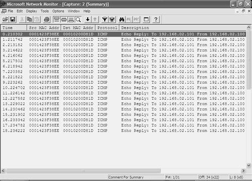
In Figure 10-17, the display has been configured to display only ICMP traffic. Comparing Figure 10-17 with Figure 10-14, notice that only ICMP echo replies sent from Host-A to Host-B have been captured, which is due to the fact that the RSPAN source session configured on Switch-A mirrors only traffic received on interface fastEthernet0/2 from Host-A, or in other words, traffic sent by Host-A. After verifying RSPAN operation with Switch-A configured as the RSPAN source and Switch-B configured as the RSPAN destination, it is a good idea to configure RSPAN in the reverse direction, where Switch-B is configured as the RSPAN source and Switch-A is configured as the RSPAN destination. This requires Host-Z to be attached on interface fastEthernet0/3 on Switch-A, which enables Host-Z to capture traffic mirrored from Host-B attached to Switch-B. Example 10-91 demonstrates clearing current RSPAN sessions on Switch-B and creating an RSPAN source session that mirrors only traffic received on port 2/2 from Host-B. Example 10-91. Creating an RSPAN Source Session on CatOSSwitch-B> (enable) set rspan disable destination all This command will disable all remote span destination session(s). Do you want to continue (y/n) [n]? y Disabled monitoring of remote span traffic for all rspan destination ports. Switch-B> (enable) set rspan source 2/2 100 rx Rspan Type : Source Destination : - Rspan Vlan : 100 Admin Source : Port 2/2 Oper Source : Port 2/2 Direction : receive Incoming Packets: - Learning : - Filter : - Status : active In Example 10-91, the RSPAN destination session previously configured is removed, using the set rspan disable destination all command. Next, an RSPAN source session is configured. Because Switch-B is a Catalyst 6000/6500 switch, notice that you don't have to configure a reflector port. If Switch-B were a Catalyst 2900/4000 switch, a reflector port would need to be configured, as demonstrated in Example 10-92. Example 10-92. Creating an RSPAN Source Session on the Catalyst 2900/4000 cat4000> (enable) set rspan source 2/2 100 reflector 2/48 rx Rspan Type : Source Destination : - Reflector : Port 2/48 Rspan Vlan : 100 Admin Source : Port 2/2 Oper Source : Port 2/2 Direction : receive Incoming Packets: - Learning : - Filter : - Status : active In Example 10-92, notice that a reflector port of port 2/48 is created, which must be an unused port on the switch. Now that an RSPAN source session is configured on Switch-B, an RSPAN destination session is required on Switch-A. Example 10-93 demonstrates clearing all RSPAN source sessions on Switch-A and then creating an RSPAN destination session. Example 10-93. Configuring an RSPAN Destination Session on Cisco IOSSwitch-A# configure terminal Switch-A(config)# no monitor session remote Switch-A(config)# monitor session 1 source remote vlan 100 Switch-A(config)# monitor session 1 destination interface fastEthernet0/3 ingress vlan 1 Switch-A(config)# exit Switch-A# show monitor Session 1 --------- Type : Remote Destination Session Source RSPAN VLAN : 100 Destination Ports : Fa0/3 Encapsulation: Native Ingress: Enabled, default VLAN = 1 In Example 10-93, the no monitor session remote command is used to remove any current RSPAN sessions (the no monitor session all command can also be used to remove all SPAN and RSPAN sessions). Next, VLAN 100 is configured as the source RSPAN VLAN and interface fastEthernet0/3 is then configured as the destination interface to which traffic received from the source RSPAN VLAN should be mirrored. The ingress vlan 1 configuration allows Host-Z to still communicate with the rest of the network on VLAN 1. At this point, assuming the continuous ping between Host-B and Host-A established in Example 10-81 is still operating, the network capture software on Host-Z should capture all traffic received by Host-B, as shown in Figure 10-18. Figure 10-18. Traffic Received by Host-B Captured on Host-Z Using RSPAN
In Figure 10-18, the display has been configured to display only ICMP traffic. Comparing Figure 10-18 with Figure 10-14, notice that only ICMP echo requests sent from Host-B to Host-A have been captured, which is due to the fact that the RSPAN source session configured on Switch-B in Example 10-91 only mirrors traffic received on port 2/3 from Host-B, or in other words, traffic sent by Host-B. Configuring VACLsAs a final configuration task, you now learn how to configure the capture feature of VLAN access control lists to capture traffic. Using VACLs to capture traffic is a feature supported only on the Catalyst 6000/6500 switch and requires a policy feature card (PFC) installed. Using VACLs to capture traffic provides some benefits over the use of SPAN, in that you can specify what types of traffic you want to capture based upon Layer 3 (IP) and Layer 4 (e.g., TCP, UDP, and ICMP) parameters. There are also no SPAN or RSPAN session limitations to worry about. The only limitation when using VACLs to capture traffic is TCAM usage, which is unlikely to be exhausted in most environments. Configuring VACLs to capture traffic requires the following configuration tasks:
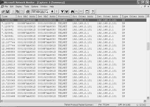
In this scenario, the management address of Switch-A is placed into VLAN 2, with an IP address of 192.168.2.1 configured. This enables Host-B to establish a Telnet connection to Switch-A, while at the same time generate ICMP traffic to Host-A. VACLs are then configured on Switch-B to capture only the Telnet traffic generated by Host-B. Example 10-94 shows the configuration required on Switch-A to modify the management address of Switch-A to 192.168.2.1 and then verify connectivity to Host-B in VLAN 2. Example 10-94. Reconfiguring the Management Address on Switch-ASwitch-A# configure terminal Switch-A(config)# interface vlan 1 Switch-A(config-if)# no ip address Switch-A(config-if)# exit Switch-A(config)# interface vlan 2 Switch-A(config-if)# ip address 192.168.2.1 255.255.255.0 Switch-A(config-if)# end Switch-A# ping 192.168.2.101 Type escape sequence to abort. Sending 5, 100-byte ICMP Echos to 192.168.2.101, timeout is 2 seconds: !!!!! Success rate is 100 percent (5/5), round-trip min/avg/max = 1/200/1000 ms Now that the management address of Switch-A has been modified, configuration of VACLs on Switch-B can begin. NOTE The configuration syntax for VACLs was discussed in Chapter 8, so if you are unsure of the syntax required, please refer back to Chapter 8. When configuring VACLs to capture traffic, you can selectively specify that traffic classified by each access control entry (ACE) in the VACL should be captured by simply specifying the capture keyword at the end of the ACE. Example 10-95 demonstrates creating a VACL on Switch-B that captures Telnet traffic. Example 10-95. Creating a VLAN ACLSwitch-B> (enable) set security acl ip TELNET permit tcp any any eq telnet capture TELNET editbuffer modified. Use 'commit' command to apply changes. Switch-B> (enable) set security acl ip TELNET permit any TELNET editbuffer modified. Use 'commit' command to apply changes. Switch-B> (enable) commit security acl all ACL commit in progress. ACL TELNET is committed to hardware. In Example 10-95, the first ACE is used to specify that any Telnet traffic should be permitted and should also be captured as indicated the capture keyword. The second ACE specifies that any other IP traffic should be permitted but not captured. If you don't configure the second ACE in Example 10-91, all other IP traffic is dropped by the VACL because there is an implicit deny all at the end of a VLAN ACL. After the VACL is configured, it is programmed to the PFC using the commit security acl all command. Now that a VACL has been configured that specifies the traffic you want to capture, the next configuration task is to define the list of capture ports to which the captured traffic will be mirrored. On the Catalyst 6000/6500, only a single list of capture ports exists, which is configured using the set security acl capture-ports command as demonstrated in Example 10-96. Example 10-96. Configuring the VLAN ACL Capture Port List Switch-B> (enable) set security acl capture-ports 2/3 Successfully set the following ports to capture ACL traffic: 2/3 In Example 10-96, port 2/3 (connected to Host-Z) is configured as a capture port. It is important to understand that capture ports receive traffic from all VACLs. The set security acl capture-ports command defines a global capture port list for the entire switch. If multiple VACLs are configured that capture traffic from multiple VLANs, and you want to capture traffic only from a specific VLAN, you can control exactly what traffic is mirrored out a capture port by configuring the port as an access port in the VLAN that you want. Now that the VACL has been configured and capture ports have been defined, the final configuration task is to map the VACL to the VLAN(s) for which you want to capture traffic. Example 10-97 demonstrates mapping the Telnet VACL created in Example 10-95 to VLAN 2, where Host-A, Host-B, and Switch-A are connected. Example 10-97. Mapping a VLAN ACL to a VLAN Switch-A> (enable) set security acl map TELNET 2 Mapping in progress. VLAN 2 successfully mapped to ACL TELNET. After you have mapped the VLAN ACL to VLAN 2, all traffic within VLAN 2 is inspected against the VLAN ACL. At this stage, the VACL configuration is complete on Switch-B and it is time to verify the VACL capture configuration. On Host-B, the continuous ping to Host-A should still be operational. However, some Telnet traffic now needs to be generated to test the VACL on Switch-B. Before this happens, Host-Z must be connected to port 2/3 and must be configured to start capturing traffic. Assuming the continuous ping to Host-A is still running (established in Example 10-81) and that Host-Z has been connected to port 2/3 on Switch-A and is capturing traffic, Example 10-98 demonstrates establishing a Telnet connection to the new management IP address of Switch-A. Example 10-98. Generating Telnet Traffic in VLAN 2C:\> telnet 192.168.2.1 Connecting To 192.168.2.1... User Access Verification Password: ***** Switch-A> On Host-Z, the traffic capture software should capture only the Telnet traffic generated in Example 10-98. The ICMP traffic generated between Host-B and Host-A should not be captured due to the VACL configuration, as demonstrated in Figure 10-19. Figure 10-19. Traffic Captured on Host-Z Using VACL Capture
In Figure 10-19, you can see that only Telnet traffic has been captured between Host-B and Switch-A. No ICMP packets or any other type of packets have been captured, indicating the VACL capture configuration is working. | |||||||||||||||||||||||||||||||||||||||||||||||||||||||||||||||||||||||||||||||
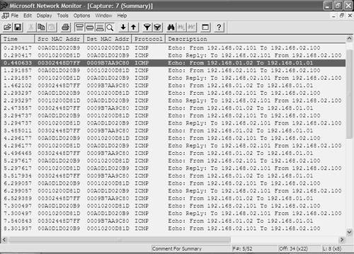

 Host-B traffic. However, the return ICMP echo reply from Switch-A to Switch-B is not being captured. This is because traffic generated by the switch CPU on the Catalyst 3550 is not mirrored to a SPAN session. The CPU on Switch-A must generate ICMP echo replies to the echo requests sent from Switch-B; hence, these replies are not mirrored to the destination SPAN interface. The ICMP echo request traffic from Switch-B to Switch-A is being captured, as this traffic is received on interface fastEthernet0/1 within VLAN 1.
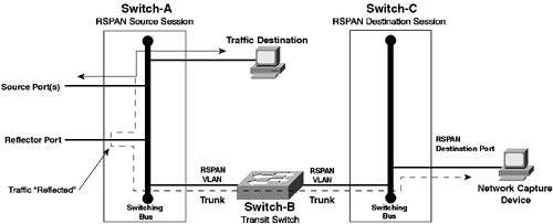
EAN: 2147483647
Pages: 135