Scenario 7-3: Multicast Traffic Control on the LAN
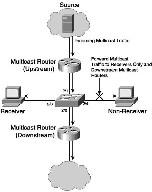
| The primary goal of multicast is to enable traffic to be sent from a single source to a specific group of devices, without requiring the traffic to be flooded throughout the network to meet the goal of ensuring all receivers interested in the traffic receive the traffic. Scenarios 7-1 and 7-2 showed you how to implement multicast routing, which is a Layer 3 function that is independent of Layer 2 (the only effect Layer 2 has on multicast routing is related to how PIM operates on point-to-point and multi-access Layer 2 networks). Multicast routing is concerned with providing multicast traffic control in Layer 3 topologies, where multicast traffic is sent across the minimum number of Layer 3 paths in the network to ensure all receivers can receive multicast traffic. Multicast routing gets the traffic for a particular multicast group to only the Layer 2 segments that need to receive the group traffic. Once the multicast transmission is on the Layer 2 network, multicast routing has no control over which Layer 2 links or ports the transmission is sent to. This control is left to the Layer 2 device (such as a switch) that interconnects the segment. You can allow the Layer 2 device to forward the multicast out all ports, treating multicasts in an identical fashion to broadcasts. This strategy certainly makes multicasts much easier to deal with from the Layer 2 device point of view, but it defeats the whole concept of multicasting. The real problem with taking the broadcast approach to multicasting is performance. If you are multicasting a large video stream out all ports, the bandwidth available to all network devices decreases. To control the multicast bandwidth usage, you can use a technique known as broadcast control, where excessive multicast (and broadcast) traffic over a certain threshold is dropped. However, this technique can have serious side effects. For example, a large multicast stream might reach the allowable multicast/broadcast threshold on a port. After this point, all multicasts and broadcasts are dropped (including crucial spanning tree BPDUs), which can cause network instability. Ideally, the Layer 2 device should forward the multicast transmission only out ports to which receivers are connected and also out any ports that are connected to downstream multicast routers. Figure 7-16 illustrates this concept. Figure 7-16. Multicast Forwarding on a Layer 2 Network
Figure 7-16 shows that it is the responsibility of the switch (rather than the router) to control which ports the multicast is flooded to. The switch must forward the multicast out ports 2/2 and 2/3 to ensure that the locally attached receiver and the rest of the multicast network receive the multicast; however, the non-receiver attached to port 2/4 does not need to receive the multicast. Layer 2 devices, such as the switch in Figure 7-16, must possess some understanding of multicast in order to control the forwarding of multicast traffic out each Layer 2 link. Cisco Catalyst switches can use the following methods of controlling multicast transmissions, which are discussed in this section:
This scenario continues on from the previous scenario and examines using static bridge table entries to constrain multicast traffic on the LAN to specific ports attached to multicast receivers. NOTE GMRP is a standards-based protocol that provides constrained multicast flooding on Layer 2 networks, in a similar fashion to IGMP snooping (see Scenario 7-4) and CGMP (see Scenario 7-5). A major drawback to GMRP is that multicast receivers (hosts) must support GMRP and send GMRP joins in addition to IGMP joins. The GMRP joins are received by a GMRP-aware switch, which uses this information to associate the ports attached to receivers with a particular multicast group. IGMP snooping and CGMP achieve the same results, but do so transparently to multicast receivers (i.e., multicast receivers need to use IGMP only to register to a multicast group and do not need to understand another protocol). Static Bridge Table EntriesThe simplest and most easily understood method of controlling multicast traffic on Layer 2 networks is to manually associate the appropriate destination ports with each multicast address. Because a multicast address is always a destination address, an entry can be placed in the bridge table of a switch that lists the appropriate egress ports for the multicast transmission. Forwarding of the multicast frames operates in identical fashion to that of unicast framesthe multicast destination MAC address is located in the local bridge table, the egress ports are found, and then a copy of the multicast frame is forwarded out each egress port. If the multicast destination MAC address is not present in the bridge table, then the frame is flooded out all ports within the VLAN, in an identical fashion to how frames to unknown unicast destination MAC addresses are flooded. Referring back to Figure 7-6, notice that on the 10.6.0.0/16 subnet, Switch-B has four devices connected:
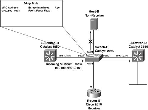
Because L3-Switch-B is the upstream multicast router for (10.1.1.10,239.1.1.1), multicast frames are received from L3-Switch-B inbound on interface Fa0/1 on Switch-B. Switch-B then needs to forward the multicast frame out interface Fa0/3 (connected to Router-B) and interface Fa0/2 (connected to L3-Switch-D), but does not need to forward the multicast frame out interface Fa0/4 (connected to the non-receiver Host-B). Figure 7-17 illustrates how you can use static bridge table entries to control multicast traffic on the 10.6.0.0/16 subnet in Figure 7-6. Figure 7-17. Multicast Traffic Control Using Static Bridge Table Entries
Notice in Figure 7-17 that a static bridge table entry exists that indicates that frames with a destination MAC of address 0100.5e01.0101 (the Ethernet multicast address for the 239.1.1.1 IP multicast address) are forwarded out interface Fa0/2 (to L3-Switch-D) and interface Fa0/3 (to Router-B). If the frames are received on interface Fa0/1, they are not forwarded back out interface Fa0/1, even though interface Fa0/1 is in the egress interface list. Also, notice that the age of the entry in the bridging table is not specified because this entry is a static bridge table entry that always remains in the bridge table and, thus, never ages out. NOTE You might be wondering why interface Fa0/1 is included in the egress interface list when group traffic is normally received on this interface. Because receivers periodically send IGMP membership reports to the group address (in response to IGMP general queries), to ensure that these messages are sent to multicast routers all interfaces with multicast routers attached must be added to the egress interface list. When configuring static bridge table entries, ensure that all groups configured include all multicast router interfaces in the egress interface list. A few issues with static bridge table entries make it difficult to use in anything but the simplest multicast networks:
The underlying problem is the lack of ability to dynamically adapt to changes in the network. The switch cannot dynamically add or remove an egress port/interface from the bridge table entry; an administrator must manually configure it. In all but the very simplest networks, the administrative overhead of implementing static bridge table entries to constrain multicast traffic on the LAN is far too high. Configuration TasksAs already indicated, implementing static bridge table entries to constrain multicast flooding on the LAN is very simple. The configuration of static bridge table entries for multicast is identical to the configuration required for static bridge table entries that reference unicast addresses (see Chapter 2, "VLAN Operations"), except you may need to specify more than one egress port or interface for the entry, depending on the number of receivers and downstream multicast routers connected to the LAN. In Figure 7-6, a single multicast source and group is present on the network. This source/group is represented in (S,G) notation as (10.1.1.10,239.1.1.1), where 10.1.1.10 (Router-A) is the source and 239.1.1.1 is the multicast group address. On the LAN segments in Figure 7-6, the Ethernet multicast address for the 239.1.1.1 IP multicast address is 0100.5e01.0101 (see Figure 7-1 if you are unsure how this is derived). Two LAN segments in the network contain receiversthe 10.5.0.0/16 subnet, which is provided LAN connectivity by Switch-C (CatOS Catalyst 6500), and the 10.6.0.0/16 subnet, which is provided LAN connectivity by Switch-B (Cisco IOS Catalyst 2950). Both segments have non-receivers and receivers that are connected locally; hence, both of these switches should ensure that multicast traffic is constrained to receivers only (and downstream multicast routers if applicable). To configure static bridge table entries for multicast frames on CatOS (also referred to as CAM entries on CatOS switches), you should first disable IGMP snooping if applicable (IGMP snooping is supported and enabled by default on the Catalyst 5000/5500 and Catalyst 6000/6500 switches) by using the set igmp command: Console> (enable) set igmp disable Once IGMP snooping has been disabled, you can then configure static bridge table entries by using the set cam command: Console> (enable) set cam {static | permanent} destination-mac mod/port [vlan-id] If you use the static keyword, the entry remains in the bridge table only until the bridge table is cleared or the switch is rebooted. To ensure the entry is always present in the bridge table even after a switch reboot, use the permanent keyword. If you don't specify the optional vlan-id parameter, VLAN 1 is assumed as the VLAN for which the entry applies. Thus if you need to control multicast traffic in a VLAN other than VLAN 1, ensure that you specify the vlan-id to indicate to which VLAN an entry should apply. In Figure 7-6 on the 10.5.0.0/16 subnet, Router-C is the only connected receiver for (10.1.1.10,239.1.1.1), with L3-Switch-B forwarding IP multicast frames onto the subnet (L3-Switch-B has asserted the role of the multicast router from L3-Switch-C for the LAN, as described in Figure 7-9). This means that on Switch-C, multicast frames need to be forwarded out port 2/1, 2/2, and 2/4. Example 7-34 demonstrates configuring a static bridge table entry on Switch-C. Example 7-34. Configuring Static Bridge Table Entries on Switch-CSwitch-C> (enable) set igmp disable IGMP Snooping is disabled. CGMP is disabled. Switch-C> (enable) set cam permanent 01-00-53-01-01-01 2/1-2,2/4 1 Permanent multicast entry added to CAM table. Switch-C> (enable) show cam permanent * = Static Entry. + = Permanent Entry. # = System Entry. R = Router Entry. X = Port Security Entry $ = Dot1x Security Entry VLAN Dest MAC/Route Des [CoS] Destination Ports or VCs / [Protocol Type] ---- ------------------ ----- ------------------------------------------- 1 01-00-5e-01-01-01 + 2/1-2,2/4 ! Permanent Bridge Table Entry Total Matching CAM Entries Displayed =1 The show cam permanent command verifies the configuration and indicates that any frame received with a destination MAC address of 0100.5e01.0101 is forwarded out port 2/4. The + symbol next to the entry indicates that this is a permanent entry. To configure static bridge table entries for multicast frames on Cisco IOS, you must first ensure that IGMP snooping is disabled (IGMP snooping is enabled by default on Cisco IOS Catalyst switches). To disable IGMP snooping, use the no ip igmp snooping global configuration command: Switch(config)# no ip igmp snooping Once IGMP snooping is disabled, you can use the mac-address-table static global configuration command to add a new entry to the bridge table: Switch(config)# mac-address-table static multicast-mac-address vlan vlan-id interface interface-id1 interface-id2 ... In Cisco IOS, the static keyword means that the entry is always present in the bridge table even after a switch reboot, unlike the CatOS set cam command where the static keyword saves the entry only until the bridge table is cleared or the switch is rebooted (i.e., the static keyword in Cisco IOS is equivalent to the permanent keyword in CatOS). Notice that you must also specify the appropriate VLAN ID for which the entry applies. In Figure 7-6, Router-B is the only connected receiver on the 10.6.0.0/16 subnet for (10.1.1.10,239.1.1.1), with L3-Switch-B forwarding frames onto the LAN and L3-Switch-D acting as a downstream multicast router. This configuration means that multicast frames need to be forwarded out interface Fa0/1, Fa0/2, and Fa0/3. Example 7-35 demonstrates configuring a static bridge table entry on Switch-B. Example 7-35. Configuring Static Bridge Table Entries on Switch-BSwitch-B# configure terminal Switch-B(config)# no ip igmp snooping Switch-B(config)# multicast-address-table static 0100.5e01.0101 vlan 1 interface FastEthernet0/1 FastEthernet0/2 FastEthernet0/3 Switch-B(config)# end Switch-B# show mac-address-table multicast Vlan Mac Address Type Ports ---- ----------- ---- ----- 1 0100.5e01.0101 USER Fa0/1 Fa0/2 Fa0/3 ! Permanent Entry Example 7-35 shows that you can use the show mac-address-table multicast command to view all bridge table entries that reference multicast destination MAC addresses. The Type field indicates a type of USER, which means that a user has manually configured the entry. |
EAN: 2147483647
Pages: 135