Scenario 7-2: Configuring PIM Sparse Mode and PIM Sparse-Dense Mode Multicast Routing
| In the previous scenario, you learned how to configure PIM dense mode multicast routing. PIM dense mode is normally a good place to start learning about PIM because it certainly represents the simplest mode of operation. However, PIM dense mode is inefficient because it initially floods all multicast traffic throughout the network and then prunes back the multicast forwarding tree to only those links required to ensure all receivers for a particular group can receive the multicast traffic for the group. Taking this approach is similar to the concept of throwing a bucket of water over a cup of water in order to fill the cup of waterclearly an inefficient mechanism. NOTE Before bagging PIM dense mode to your fellow network engineers, there is absolutely no reason why you can't use PIM dense mode in a high-bandwidth network that has plenty of bandwidth to throw around. Unfortunately, this scenario is seldom the case and PIM dense mode often causes congestion in low-bandwidth networks when a new multicast source comes online. In this scenario you learn how to configure PIM sparse mode multicast routing, as well as a special mode of PIM called sparse-dense mode routing. NOTE The same topology of Scenario 7-1 is used for this scenario (see Figure 7-6), however it is assumed that each device has the base configuration as described in the scenario prerequisites section of Scenario 7-1 (see Table 7-2), as well as a complete unicast routing topology as configured in Example 7-2. The unicast routing considerations and neighbor discovery mechanisms in PIM sparse mode and sparse-dense mode are identical to PIM dense mode, but how multicast forwarding trees are built differs. The following sections provide an introduction to PIM sparse mode and sparse-dense operation and then show you how to configure PIM sparse and PIM sparse-dense mode:
Building Multicast Trees in PIM Sparse Mode NetworksPIM sparse mode (PIM-SM) is reasonably complex in how multicast distribution trees are formed because a variety of multicast distribution trees are used to forward traffic for a multicast group. PIM-SM initially uses a shared tree that flows from a shared root (multicast router) in the network known as a rendezvous point (RP) and also uses a shortest path tree (SPT) to allow each source to forward traffic to the rendezvous point. The rendezvous point then receives multicast traffic from the source via the SPT and then forwards the multicast traffic down the shared tree to the various receivers. The goal of these two initial multicast distribution trees is to allow new multicast sources to be added to the multicast routing topology, without flooding multicast traffic to all links in the network (as is the case with PIM-DM). Once a new source is known to the network, PIM-SM can then form a SPT rooted at the source of a group, which ensures the most optimal multicast distribution tree is formed, without requiring the inefficient flooding that occurs with PIM-DM. The following describes the various stages that exist in PIM-SM operation:
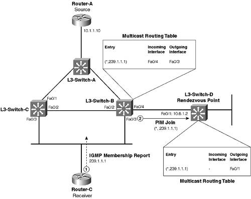
Each of these stages of PIM-SM operation is now discussed in detail. Building the Shared TreeThe first phase of PIM-SM operation is when receivers initially indicate their intention to join a group. At this point, assuming no sources are active for the group on the network, each multicast router that has receivers attached will join a shared tree that is rooted at a configured RP in the network. Figure 7-11 demonstrates this process. Figure 7-11. Building the Shared Tree in PIM-SM Operation
In Figure 7-11, assume that the network has been configured for sparse mode operation. Router-C is a receiver that has just attached to the network and wants to join the 239.1.1.1 group.
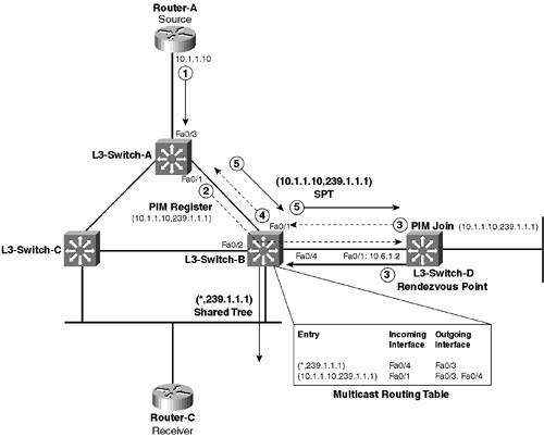
NOTE On a multi-access network that has multiple multicast routers attached (such as the LAN that Router-C is connected to), only the PIM designated router (DR) sends PIM Join messages. The PIM DR is chosen as the multicast with the highest IP addressed interface on the LAN. For example, in Figure 7-11 on the 10.5.0.0/16 subnet, L3-Switch-B is the PIM DR because it has a higher IP address on the subnet than L3-Switch-C. Consequently, only L3-Switch-B generates PIM Joins for receivers attached to the 10.5.0.0/16 subnet because it is the PIM DR for this subnet. If multiple hops exist between the initial multicast router that generates the (*,G) PIM Join and the RP, each upstream PIM router accepts PIM Joins from downstream routers, creates the appropriate (*,G) entry in the multicast routing table, and then sends a PIM Join to the next upstream router. This process is repeated until the PIM Join finally reaches the RP and creates a (*,G) shared tree that includes the shortest path in the network between the RP and the receiver that originally caused the PIM Join to be sent. Once the RP (L3-Switch-D) receives the PIM Join, it also creates a (*,239.1.1.1) entry in the local multicast routing table, which specifies an outgoing interface of Fa0/1. This entry ensures that any traffic received from a source for the 239.1.1.1 group is forwarded down the shared tree generated in Figure 7-11. NOTE The concept of an incoming interface for the (*,239.1.1.1) entry on the RP does not apply, as the RP is the root of the shared tree. Building a Shortest Path Tree from the Source to the Rendezvous PointIn Figure 7-11, a (*,239.1.1.1) shared tree has been generated that enables the RP to forward multicast traffic to receivers for the 239.1.1.1 group. At this point, however, no source is actually sending multicast traffic to the RP, and some mechanism must be available to ensure the RP receives traffic from a source if a source comes online. A source has no concept of PIM, let alone rendezvous points, and sends multicast traffic only out onto the LAN the source is connected to, relying on the network to forward the traffic to any receivers for the group. Therefore, the first multicast router that receives multicast traffic from the source must somehow ensure that the multicast traffic received is forwarded to the RP. Figure 7-12 demonstrates how this is achieved. Figure 7-12. Building an SPT from the Source to the RP
In Figure 7-12, the (*,239.1.1.1) shared tree built in Figure 7-11 is shown as the thick black arrows. Router-A (a source) is about to start sending multicast packets to the 239.1.1.1 group. The following describes the events that occur:
When L3-Switch-B receives multicast traffic for the (10.1.1.1,239.1.1.1) SPT from L3-Switch-A, it forwards the multicast traffic out Fa0/4 (towards the RP) and also out Fa0/2. This configuration ensures that the RP receives multicast traffic via the shortest path possible from the source, which it can then forward down the shared tree to receivers. Because the RP is now receiving multicast traffic for the (S,G) SPT via native multicast packets, as opposed to unicast PIM Register messages, the RP sends a unicast PIM Register-Stop message to L3-Switch-A, which informs L3-Switch-A (the originator of PIM Register messages in Step 2) to stop sending PIM Register messages. This completes the building of the SPT between the source and the RP, ensuring traffic flows down the SPT from the source to the RP and then down the shared tree from the RP to any receivers. Notice that because the SPT and shared trees intersect at L3-Switch-B, multicast traffic sent down the (10.1.1.10,239.1.1.1) SPT towards the RP are actually forwarded down the shared tree at L3-Switch-B bypassing the RP because this represents a more efficient path to reach receivers. NOTE L3-Switch-B ignores any (10.1.1.10,239.1.1.1) multicast packets received on the interface attached to the RP, because these packets fail an RPF check. Ignoring these packets ensures receivers do not receive duplicate multicast packets sent via L3-Switch-B and via the RP. Building a Shortest Path Tree from the Source to All ReceiversIf you look at the multicast distribution trees that have been generated so far, the combination of the SPT from the source to the RP and the shared tree from the RP to each receiver ensures multicast traffic can be forwarded to all receivers, but does not represent the most efficient multicast forwarding path through the network. For example, the most efficient path between Router-A (source) and Router-C (a receiver) is via L3-Switch-A Figure 7-13. Demonstrating the Inefficiencies of a Combined SPT and Shared Tree Multicast Distribution Tree
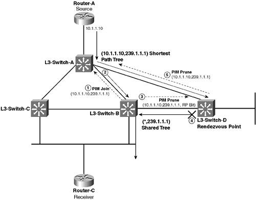
In Figure 7-13, because the SPT and shared tree intersect only at the RP, all traffic sent from the source must be sent across three hops (L3-Switch-A Once a receiver starts receiving multicast traffic from a source, both the receiver and the multicast routers attached to the receiver know the IP address of the source. This knowledge means that the locally connected multicast routers can join the (S,G) SPT, so that the most optimal multicast forwarding path is taken between the source and receivers. Figure 7-14 demonstrates this for the topology of Figure 7-13. Figure 7-14. Building the SPT from the Source to Receivers
In Figure 7-14, the following events occur:
At this point, an SPT has been formed between the source and receiver, ensuring only the most optimal path in the network is chosen to route multicast traffic to receivers. NOTE Multicast routers cannot initially form an (S,G) SPT to the source (S) when a receiver first announces its membership to the group , if no source currently exists for the group. Each PIM-SM multicast router that has receivers attached joins the (*,G) shared tree to the RP, which ensures that once a source does come online for the group, each multicast router receives the traffic. Once a PIM-SM multicast router receives actual multicast packets from a source, the multicast router now knows the IP address of the source and can form an SPT to the source. Essentially, the RP provides a mechanism for PIM-SM multicast routers to discover sources and then form an SPT to each source. You might be wondering why you even use PIM sparse mode, if all it ultimately provides is an SPT between source and receiver. PIM dense mode also does this, so why go to the trouble of implementing PIM sparse mode, which is clearly much more complex for multicast routers to deal with? The answer is that PIM sparse mode removes the inefficient requirement of PIM dense mode to initially flood all multicast traffic throughout the network and then prune back the multicast distribution tree as required. Instead, PIM sparse mode requires only initial forwarding of traffic from the source to the RP (initially via unicast and then via multicast once an SPT is built from the source to the RP) and then from the RP down to each receiver via the shared tree. This forwarding is clearly more efficient than that offered by PIM dense mode because significantly less multicast traffic is initially flooded on the network. Once PIM sparse mode multicast routers know about a source that is sending multicast traffic, they can immediately create or join the (S,G) SPT by sending PIM Joins upstream toward the source. Configuration TasksThis scenario demonstrates the configuration of Catalyst 3550 Layer 3 switches for IP multicast routing using PIM sparse mode operation. Configuration of multicast routing on the Catalyst 3550 switches is identical to the configuration required on Cisco routers because both devices use Cisco IOS. The tasks required to enable multicast routing using PIM-SM include the following:
The unicast routing configuration required for PIM-SM is identical to that required for PIM-DM; hence, this configuration task is not covered in this scenario (refer to Scenario 7-1 for coverage of this task). All subsequent configuration tasks presented in this scenario assume a complete unicast routing topology is in place. Configuring the Rendezvous PointAs indicated previously in this scenario, the RP provides a very important role in PIM sparse mode operation. Without an RP, there is no way for PIM-SM routers with receivers attached to join the appropriate (*,G) shared tree, and there is also no way for PIM-SM routers with sources attached to send PIM Register messages to the root of the shared tree. It is important to understand that the RP is a multicast router and, therefore, requires multicast routing to be configured. On an RP, the following multicast routing configuration is required:
To globally enable multicast routing, use the ip multicast-routing global configuration command. To configure an interface to support PIM sparse mode, use the ip pim interface configuration mode command: Router(config-if)# ip pim sparse-mode Once you have configured the prerequisites for an RP, you can next configure the RP feature itself. The method by which you configure the RP depends on how you want the multicast network to discover the RP. If you manually configure the RP on each multicast router in the network, you simply need to configure the RP with an RP IP address that points to itself. This configuration is performed using the ip pim rp-address command: Router(config)# ip pim rp-address ip-address [access-list-number] [override] NOTE If you configure RP discovery protocols for discovery of the RP, you do not need to configure the previous command on the RP. The access-list-number parameter specifies the number of a standard access control list configured on the router that defines all groups for which the router is the RP. The override keyword indicates that if a different RP for a group is learned via a mechanism such as Auto-RP, the IP address configured for this command takes precedence. TIP If multiple paths to an RP exist in the network, you should create a loopback interface on the RP, assign an IP address to the loopback interface, and use the loopback IP address for the RP. If you use a physical interface for the RP and if that physical interface goes down, the RP stops working. If you want for the network to use an automated discovery mechanism to locate the RP, you need to configure the RP to support the appropriate discovery mechanism. For this scenario, assume that the RP is configured manually on each multicast router. Example 7-21 demonstrates the configuration required on the RP (L3-Switch-D) if the RP is configured manually on all other multicast routers. Example 7-21. Configuring an RPL3-Switch-D# configure terminal L3-Switch-D(config)# access-list 1 permit 239.1.1.0 0.0.0.255 L3-Switch-D(config)# ip pim rp-address 10.6.1.2 1 L3-Switch-D(config)# ip multicast-routing L3-Switch-D(config)# interface range FastEthernet0/1 - 2 L3-Switch-D(config-if-range)# ip pim sparse-mode In Example 7-21, an access control list (ACL) is created and defined as the list of groups that the RP represents. The ACL permits only multicast groups in the 239.1.1.x range (all ACLs have an implicit drop at the end of the ACL). Notice that the configured IP address of the RP is 10.6.1.2, which is the Fa0/1 interface on L3-Switch-D. All other multicast routers must be configured with this IP address for the RP to ensure correct PIM sparse mode operation. Configuring PIM Sparse Mode Multicast RoutingAfter the RP is configured, you should then configure all other multicast routers in the network. Before you can configure PIM sparse mode, you must globally enable multicast routing, which is performed using the ip multicast-routing global configuration command. Once multicast routing is in place, if the network is using manual configuration to define the IP address of the RP, you must manually configure the IP address of the RP on each multicast router. This configuration ensures that each multicast router can join (*,G) shared trees rooted at the RP and send PIM Register messages to the RP. To configure the IP address of the RP, you use the same ip pim rp-address global configuration command that is also configured on the RP. Example 7-22 demonstrates the configuration required on L3-Switch-A to enable multicast routing and configure PIM sparse mode. Example 7-22. Configuring a PIM Sparse Mode RouterL3-Switch-A# configure terminal L3-Switch-A(config)# access-list 1 permit 239.1.1.0 0.0.0.255 L3-Switch-A(config)# ip multicast-routing L3-Switch-A(config)# ip pim rp-address 10.6.1.2 1 L3-Switch-A(config)# interface range FastEthernet0/1 - 3 L3-Switch-A(config-if-range)# ip pim sparse-mode In Example 7-22, because the RP has been configured to act as the RP only for groups in the 239.1.1.x address range, you should also configure all other multicast routers with this information, using ACLs as indicated. Notice that you use the same command (ip pim rp-address) that was used on the RP itself to configure the RP on other routers. The configuration of Example 7-22 must be configured on all other multicast routers in the network to ensure each router knows where the RP is located in the network. NOTE Dynamic RP discovery mechanisms eliminate the requirement to manually configure the RP and the groups the RP represents. For this reason, use dynamic RP discovery mechanisms in larger networks to save administrative overheads. Example 7-23 demonstrates the configuration required on L3-Switch-B to enable multicast routing and configure PIM sparse mode. Example 7-23. Configuring PIM Sparse Mode Operation on L3-Switch-BL3-Switch-B# configure terminal L3-Switch-B(config)# access-list 1 permit 239.1.1.0 0.0.0.255 L3-Switch-B(config)# ip multicast-routing L3-Switch-B(config)# ip pim rp-address 10.6.1.2 1 L3-Switch-B(config)# interface range FastEthernet0/1 - 4 L3-Switch-B(config-if-range)# ip pim sparse-mode Example 7-24 demonstrates the configuration required on L3-Switch-C to enable multicast routing and configure PIM sparse mode. Example 7-24. Configuring PIM Sparse Mode Operation on L3-Switch-CL3-Switch-C# configure terminal L3-Switch-C(config)# access-list 1 permit 239.1.1.0 0.0.0.255 L3-Switch-C(config)# ip multicast-routing L3-Switch-C(config)# ip pim rp-address 10.6.1.2 1 L3-Switch-C(config)# interface range FastEthernet0/1 - 4 L3-Switch-C(config-if-range)# ip pim sparse-mode Verifying PIM Sparse Mode Multicast RoutingOnce you have configured PIM sparse mode multicast routing on each multicast router (assuming that the unicast routing topology is in place correctly), verify your interface configuration. Then verify that all multicast routers can see each other as PIM neighbors using the show ip pim neighbor command (see Example 7-9 in Scenario 7-1). This command is important for PIM sparse mode operation because it enables you to determine the PIM DR on each multi-access network. The PIM DR is the multicast router that sends PIM Joins for (*,G) shared trees to the RP. Once you have verified that all multicast routers can see all neighbors, it is a good idea to verify that RPF checks are going to work correctly when your multicast sources start to transmit traffic. The show ip rpf command can be used to perform an RPF check manually for any source address, allowing you to verify that the correct unicast routing information is in place (see Example 7-11 in Scenario 7-1). Testing PIM Sparse Mode OperationOnce the PIM sparse mode configuration of the network has been verified, the network is ready to begin forwarding multicast traffic. In this scenario, the topology of Figure 7-6 is used, where a single Cisco router (Router-A) with an IP address of 10.1.1.10 is used as the source of multicast traffic for the group address 239.1.1.1, and several Cisco routers (Router-B and Router-C) are configured as multicast receivers for the 239.1.1.1 group address. L3-Switch-D is configured as the RP for the network. As described in this scenario, several multicast distribution trees are used to forward multicast traffic over a PIM sparse mode network. Initially, when receivers for groups are attached to the network but no sources are sending, a shared tree (*,G) exists for each group that is rooted at the RP and extends to the appropriate multicast routers with receivers attached. In this scenario, a (*,239.1.1.1) shared tree is initially formed from the RP to all receivers. Assume that Router-C has just come online and has sent an IGMP Membership Report for the 239.1.1.1 group. L3-Switch-B is the PIM DR for the 10.5.0.0/16 subnet because it has the highest IP addressed interface of any PIM router on the subnet, so L3-Switch-B sends PIM Joins for the (*,239.1.1.1) shared tree when Router-B (or any receiver on the 10.5.0.0/16 subnet) comes online. Example 7-25 shows the output of the debug ip igmp and debug ip pim commands on L3-Switch-B when Router-C comes online and sends an IGMP Membership Report. Example 7-25. Building the (*,G) Shared Tree to the RPL3-Switch-B# debug ip igmp IGMP debugging is on L3-Switch-B# debug ip pim PIM debugging is on ! Router-C sends an IGMP Membership Report for the 239.1.1.1 Group 00:42:32: IGMP: Received v2 Report on FastEthernet0/3 from 10.5.1.10 for 239.1.1.1 00:42:32: IGMP: Received Group record for group 239.1.1.1, mode 2 from 10.5.1.10 for 0 sources 00:42:32: IGMP: WAVL Insert group: 239.1.1.1 interface: FastEthernet0/3Successful 00:42:32: IGMP: Switching to EXCLUDE mode for 239.1.1.1 on FastEthernet0/3 00:42:32: IGMP: Updating EXCLUDE group timer for 239.1.1.1 ! Router-C creates (*,239.1.1.1) entry and sends PIM Join to the RP 00:42:32: PIM: Check RP 10.6.1.2 into the (*, 239.1.1.1) entry 00:42:32: PIM: Building triggered (*,G) Join / (S,G,RP-bit) Prune message for 239.1.1.1 00:42:32: PIM: v2, for RP, Join-list:10.6.1.2/32, RP-bit, WC-bit,S-bit 00:42:32: PIM: batch v2 Join on FastEthernet0/4 to 10.6.1.2 for (10.6.1.2/32, 239.1.1.1), WC-bit, RPT-bit, S-bit 00:42:32: PIM: Building batch join message for 239.1.1.1 00:42:32: PIM: Send v2 batch join to 10.6.1.2 (FastEthernet0/4) The various events indicated by the output of Example 7-23 are illustrated in Figure 7-11. You can see that as soon as Router-C sends the IGMP Membership Report (Step 1 in Figure 7-11), L3-Switch-B generates a PIM Join for the (*,239.1.1.1) shared tree to the RP (Step 2 in Figure 7-11). Example 7-26 shows the multicast routing table on L3-Switch-B after the events of Example 7-25, using the show ip mroute command. Example 7-26. The Multicast Routing Table on L3-Switch-B After Joining the (*,239.1.1.1) Shared TreeL3-Switch-B# show ip mroute IP Multicast Routing Table Flags: D - Dense, S - Sparse, s - SSM Group, C - Connected, L - Local, P - Pruned, R - RP-bit set, F - Register flag, T - SPT-bit set, J - Join SPT, M - MSDP created entry, X - Proxy Join Timer Running A - Advertised via MSDP, U - URD, I - Received Source Specific Host Report Outgoing interface flags: H - Hardware switched Timers: Uptime/Expires Interface state: Interface, Next-Hop or VCD, State/Mode (*, 239.1.1.1), 00:29:06/00:02:34, RP 10.6.1.2, flags: SJC Incoming interface: FastEthernet0/4, RPF nbr 10.6.1.2 Outgoing interface list: FastEthernet0/3, Forward/Sparse, 00:29:06/00:00:00, H ... <output truncated> ... The output shows that an entry for (*,239.1.1.1) has been created. You can see that the RP associated with the entry is 10.6.1.2 (L3-Switch-D), with the flags (SJC) indicating that the entry is a sparse mode entry (S) and that a receiver is directly connected to the router. The J flag (Join SPT) indicates that the SPT threshold is being exceeded (remember that by default, this threshold is 0 kbps), which means that the next (S,G) packet that is seen and has the same group address as the (*,G) entry (i.e., 239.1.1.1) triggers a PIM (S,G) Join to be sent towards the source, forming an SPT to the source. Notice that the incoming interface is listed as FastEthernet0/4, which is the closest interface to the RP. The outgoing interface list includes only FastEthernet0/3, because this is the interface to which the receiver (Router-C) is attached. The H flag indicates that any multicast packets received that for the 239.1.1.1 group are Layer 3 switched in hardware, as opposed to routed in software. Example 7-27 shows the multicast routing table on L3-Switch-D after the events of Example 7-26, using the show ip mroute command. Example 7-27. The Multicast Routing Table on L3-Switch-D After Joining the (*,239.1.1.1) Shared TreeL3-Switch-D# show ip mroute IP Multicast Routing Table Flags: D - Dense, S - Sparse, B - Bidir Group, s - SSM Group, C - Connected, L - Local, P - Pruned, R - RP-bit set, F - Register flag, T - SPT-bit set, J - Join SPT, M - MSDP created entry, X - Proxy Join Timer Running, A - Candidate for MSDP Advertisement, U - URD, I - Received Source Specific Host Report Outgoing interface flags: H - Hardware switched Timers: Uptime/Expires Interface state: Interface, Next-Hop or VCD, State/Mode (*, 239.1.1.1), 00:00:45/00:03:19, RP 10.6.1.2, flags: S Incoming interface: Null, RPF nbr 0.0.0.0 Outgoing interface list: FastEthernet0/1, Forward/Sparse, 00:00:45/00:03:19 ... <Output Truncated> ... If you compare the (*,239.1.1.1) entries of Example 7-26 and Example 7-27, you can see that the entry for L3-Switch-D in Example 7-27 is a little different because it is the RP. The incoming interface is listed as Null because the RP is the root of (*,G) shared trees and, thus, has no concept of an incoming interface that leads to upstream routers. The outgoing interface is listed as FastEthernet0/1, which is attached to L3-Switch-B. This entry is present because L3-Switch-B sent the original PIM Join for (*,239.1.1.1). If the RP received any PIM joins for the shared tree on any other interfaces, these interfaces are also listed in the outgoing interface list. Example 7-26 and Example 7-27 verify the PIM sparse mode operation is working properly when receivers join a multicast group, with a shared tree being formed that is rooted at the RP. At this point, no sources are actually sending traffic. Now assume that Router-A (source) comes online and begins forwarding traffic. You can simulate this by issuing an extended ping on Router-A to the multicast group address of 239.1.1.1 (see Example 7-16 in Scenario 7-1). Once multicast traffic is sent from a source in a PIM sparse mode network, the first multicast router that receives the traffic (L3-Switch-A in this scenario) sends a PIM Register message to the RP, as indicated in Figure 7-12. Example 7-28 shows the output of the debug ip pim command on L3-Switch-A, after Router-A sends traffic to the 239.1.1.1 group. Example 7-28. Demonstrating the PIM Register Process L3-Switch-A# debug ip pim ! Multicast packet is received from Router-A (source). ! L3-Switch-A sends a unicast PIM ! Register message to the RP for (10.1.1.10,239.1.1.1), ! which includes the multicast packet 03:19:28: PIM: Check RP 10.6.1.2 into the (*, 239.1.1.1) entry 03:19:28: PIM: Send v2 Register to 10.6.1.2 for 10.1.1.10, group 239.1.1.1 ! A PIM Join for (10.1.1.10,239.1.1.1) is received from L3-Switch-B. ! This is the final ! Join used to build the SPT from the RP to the source 03:19:28: PIM: Received v2 Join/Prune on FastEthernet0/1 from 10.2.1.2, to us 03:19:28: PIM: Join-list: (10.1.1.10/32, 239.1.1.1), S-bit set 03:19:28: PIM: Add FastEthernet0/1/10.2.1.2 to (10.1.1.10/32, 239.1.1.1), Forward state ! Because the (10.1.1.10,239.1.1.1) SPT has been built, ! the RP receives multicast traffic ! down the SPT and sends a PIM Register-Stop message to L3-Switch-A 03:19:30: PIM: Received v2 Register-Stop on Ethernet1 from 10.6.1.2 03:19:30: PIM: for source 10.1.1.10, group 239.1.1.1 03:19:30: PIM: Clear register flag to 10.6.1.2 for (10.1.1.10/32, 239.1.1.1) In Example 7-28, you can see that all of the events described in Figure 7-12 take place extremely quickly. You can't see the final step of PIM sparse mode operation, where a multicast router joins the (S,G) SPT, because the (S,G) SPT generated from the RP to the source effectively builds the (S,G) SPT from L3-Switch-B to the source. Thus, the L3-Switch-B doesn't actually need to join the (S,G) SPT when it forwards the first multicast packet to receivers. Example 7-29 demonstrates the events that occur on the RP after Router-A starts generating multicast traffic by using the debug ip pim command on L3-Switch-D. Example 7-29. Demonstrating the PIM Register Process on the RP L3-Switch-D# debug ip pim ! PIM Register is received from L3-Switch-A ! Multicast packet in PIM Register message is forwarded down the shared tree 04:25:05: PIM: Received v2 Register on FastEthernet0/1 from 10.2.1.1 04:25:05: for 10.1.1.10, group 239.1.1.1 04:25:05: PIM: Forward decapsulated data packet for 239.1.1.1 on FastEthernet0/1 ! RP is sending PIM Join for (10.1.1.10,239.1.1.1) towards source to build SPT 04:25:05: PIM: Send v2 Join on FastEthernet0/1 to 10.6.1.1 for (10.1.1.10/32, 239.1.1.1), S-bit ! PIM Register-Stop message is sent to L3-Switch-A (10.2.1.1), ! as multicast packets are ! now being received via SPT instead of via PIM Register messages 04:25:07: PIM: Send v2 Register-Stop to 10.2.1.1 for 10.1.1.10, group 239.1.1.1 ! PIM Prune is sent for (10.1.1.10,239.1.1.1) from L3-Switch-B to the RP. ! The RP bit is set, to indicate that only (S,G) traffic should be pruned ! from the (*,239.1.1.1) tree 04:25:08: PIM: Received v2 Join/Prune on FastEthernet0/1 from 10.6.1.1, to us 04:25:08: PIM: Prune-list: (10.1.1.10/32, 239.1.1.1) RPT-bit set Example 7-29 shows the PIM Register messages generated from L3-Switch-A when Router-A begins sending multicast packets. The PIM messages are followed by the RP joining the (10.1.1.10,239.1.1.1) SPT. Once the SPT is built, native multicast packets are received instead of unicast PIM Register messages, and a PIM Register-Stop is sent to L3-Switch-A. Figure 7-12 illustrates each of these events. The final event in Example 7-29 is the sending of a PIM prune message from L3-Switch-B to the RP, after L3-Switch-B forms an SPT to the source. If you refer back to Figure 7-14, Step 3 illustrates this event. In Example 7-29, the last line of the output indicates that the RPT-bit is set. The RPT portion of this output indicates flags with R representing the RP bit (i.e,. the RP bit is set), P indicating the message is a prune, and T (the SPT bit) indicating that packets have been received on the SPT, as opposed to the shared tree. The prune message ensures that L3-Switch-D doesn't unnecessarily forward multicast packets towards L3-Switch-B, because L3-Switch-B is already receiving the packets down the (10.1.1.10,239.1.1.1) SPT. Configuring PIM Sparse-Dense Mode OperationPIM sparse-dense mode represents a simple extension to PIM sparse mode operation that enables PIM routers to use PIM dense mode operation for any multicast groups that do not have an RP configured. If a multicast router has all interfaces configured for PIM sparse mode operation and a receiver joins a group that is not serviced by any known RP, a shared tree can never be joined for the group because there is no RP known to the multicast router for the group. Similarly, if a multicast router receives traffic from a source for a group that is not serviced by any known RP, the multicast router simply cannot forward the traffic because it has no RP to which it can send PIM Register messages. Using the configuration presented so far in this book, the situations discussed in the previous paragraph are not really a problem because each multicast router is configured with an RP and, thus, knows where to forward multicast traffic. However, sparse mode operation does present a problem when you want to use RP discovery protocols instead of manually configuring the RP, because these protocols use multicast transmissions themselves to communicate information about RPs in the network. This situation presents an interesting problema router must know about at least one RP to forward multicast traffic, but the protocols used to advertise the location of RPs use multicast communications. The solution to this problem is to use PIM dense mode operation for the RP discovery protocols, which means that the RP discovery messages are flooded throughout the network without requiring knowledge of an RP. If you configure PIM dense mode, however, you lose the benefits of PIM sparse mode. What is needed is some mode of operation that uses PIM dense mode when an RP is not present for a group, but uses PIM sparse mode when an RP is present for a group. PIM sparse-dense mode is a mode of operation that provides this exact functionality. For each group present on the network, multicast routers configured in PIM sparse-dense mode operate in PIM sparse mode if the RP is known for the group or, alternatively, operate in PIM dense mode if the RP is unknown. Configuring PIM sparse-dense mode has no effect on your existing sparse mode network, but ensures that messages sent to groups without an RP configured (e.g., RP discovery protocols) are flooded throughout the network using PIM dense mode operation. NOTE Cisco recommends that the PIM sparse-dense mode operation always be configured over other PIM modes where possible in the network. To configure PIM sparse-dense mode operation, you simply change the PIM mode on each interface to sparse-dense mode, using the ip pim interface configuration command: Router(config-if)# ip pim sparse-dense-mode All other PIM sparse mode multicast routing configuration remains the same and is not affected by sparse-dense mode operation. The only difference in functionality is that multicast routers use PIM dense mode operation if an RP is not present for a particular multicast group. Example 7-30 demonstrates the configuration required on L3-Switch-A to enable IP PIM sparse-dense mode operation. Example 7-30. Configuring IP PIM Sparse-Dense Mode OperationL3-Switch-A# configure terminal L3-Switch-A(config)# interface FastEthernet0/1 3 L3-Switch-A(config-if-range# ip pim sparse-dense-mode Configuring Auto-RPIn the scenario so far, each multicast router has been manually configured with the RP. In a small network, this configuration is not too much of a problem, but in a large multicast network that has several RPs that each service separate multicast groups, manually configuring RP information on each and every multicast router in the network requires high administrative overhead and is prone to error. To avoid the issues of manually configuring RP information, several dynamic RP discovery mechanisms are available that automate the discovery of one or more RPs in the network and the groups that each RP services. With these mechanisms, you no longer have to manually configure every single multicast router in the network with RP information; instead, each multicast router can dynamically learn RP information. Two RP discovery protocols are available and commonly used in PIM multicast networks:
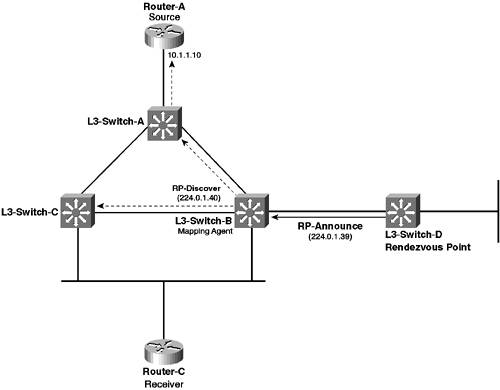
In general, Auto-RP is the recommended dynamic RP protocol because it uses multicast trees to distribute RP information. In contrast, PIMv2 BSR floods traffic throughout the network, which is less efficient than using multicast. Accordingly, this section provides information only on how to configure Auto-RP. Auto-RP is a Cisco proprietary mechanism that was invented before the PIM version 2 specification, which includes the alternative BSR RP discovery protocol. Auto-RP introduces mapping agents, which are routers that listen to messages sent to a well-known group called Cisco-RP-Announce. The Cisco-RP-Announce group has an IP address of 224.0.1.39, and any Cisco RP that is configured to announce its presence as an RP sends RP-Announce messages to this group. An RP-Announce message contains the IP address of the RP and a list of the groups that the RP services, which can be defined as a Group-to-RP mapping. Each mapping agent that receives these messages writes the Group-to-RP mappings contained in each message to a Group-to-RP mapping cache, which is stored locally in memory. These mappings contain the IP address of each RP and the groups that each RP services. The mapping agent then transmits this information to the network in RP-Discovery multicast messages, which are sent to the well-known Cisco-RP-Discovery group (224.0.1.40). All Cisco multicast routers join this group and, hence, receive all RP-Discovery messages sent by mapping agents, which enables all multicast routers to receive RP information dynamically, in a manner that is highly efficient and scalable. Figure 7-15 demonstrates how the Auto-RP works on the topology used for this scenario. Figure 7-15. Auto-RP Operation
In Figure 7-15, L3-Switch-D is the RP and is configured to send RP-Announce messages to the Cisco-RP-Announce group. L3-Switch-B is configured as a mapping agent and, thus, listens to the RP-Announce messages sent from L3-Switch-D. L3-Switch-B then propagates this information to all other multicast routers in the network by sending RP-Discovery messages to the Cisco-RP-Discovery group. L3-Switch-B essentially becomes a source for the 224.0.1.40 group, with an SPT being built to the remaining multicast routers in the network because they are receivers of this group. PIM sparse-dense mode operation is required on all multicast routers because the RP-Announce and RP-Discovery groups require PIM dense mode to flood traffic to all mapping agents and multicast routers, ensuring all multicast routers in the network can discover all available RPs. Once your network is configured for PIM sparse-dense mode operation, to configure auto-RP you must perform the following configuration tasks:
NOTE The configurations presented in this section assume that you have removed all manual configuration of the RP on L3-Switch-A, L3-Switch-B, and L3-Switch-C to ensure this information is not used to find the RP. Configuring Candidate Rendezvous PointsWhen Auto-RP is configured, all RPs in the network must be configured to belong to the Cisco-RP-Announce group, which means they periodically send RP-Announce messages indicating the IP address of the RP and the groups it services (Group-to-RP mapping). To configure an RP to do this, use the ip pim send-rp-announce global configuration command: Router(config)# ip pim send-rp-announce interface-id scope ttl group-list access-list-number interval seconds The scope keyword defines the IP TTL value that is set on the RP-Announce messages, which can be used to control how far RP-Announce messages propagate once sent. You must ensure that the TTL is large enough to reach all mapping agents in the network. The group-list keyword allows you to specify which groups the RP services by configuring an ACL that specifies each group. The interval keyword defines how often RP-Announce messages are sent; the default is every 60 seconds. NOTE If multiple RPs advertise that they service the same groups, the RP with the highest IP address is chosen as RP. This mechanism enables you to implement RP redundancy, with the highest IP addressed RP normally performing the RP role and other lower IP addressed RPs providing backup in case the primary RP fails. Example 7-31 demonstrates configuring L3-Switch-D to generate RP-Announce messages. Example 7-31. Configuring an RP for Auto-RPL3-Switch-D# configure terminal L3-Switch-D(config)# interface loopback 0 L3-Switch-D(config-if)# ip address 10.10.10.4 255.255.255.255 L3-Switch-D(config-if)# ip pim sparse-dense-mode L3-Switch-D(config-if)# exit L3-Switch-D(config)# ip pim send-rp-announce loopback 0 scope 2 group-list 1 In Example 7-31, a loopback interface is created to ensure that a physical interface failure does not stop RP-Announce messages from being generated. So, RP-Announce messages are sent via the (10.10.10.4,224.0.1.39) SPT. The scope is set to 2, which means the RP-Announce messages are propagated only two hops to L3-Switch-B (the local router is considered a single hop), which is a mapping agent. The group-list keyword references ACL #1, which was created in Example 7-21 and means that L3-Switch-D only advertises that it is the RP for groups that are within the 239.1.1.x address range. NOTE In Example 7-31, notice that you don't need to configure the ip pim rp-address command on the RP, which you do need to configure if using manual RP configuration. The ip pim send-rp-announce command tells the RP which interface it should listen on. Configuring Mapping AgentsOnce all RPs are configured to send RP-Announce messages, you must configure mapping agents to generate RP-Discover messages in response to RP-Announce messages received. The mapping agent essentially acts as a relay agentwhen RP-Announce messages are received by the mapping agent, the information contained in these messages is relayed to all multicast routers on the network using RP-Discover messages. NOTE You might wonder why all multicast routers don't just listen to RP-Announce messages to determine RP information. The answer is scalability. You may have many RPs in your network. Those RPs represent multiple sources of RP-Announce messages, each of which generates an SPT (because RP-Announce messages are sent to a multicast group). If all multicast routers listened to the RP-Announce messages, the SPTs for each source would span the entire network, which does not scale well in large networks. By using mapping agents, each RP-Announce SPT needs to span only all mapping agents, which then can aggregate all of the RP information onto a single SPT tree that is rooted at the mapping agent and distributed to all multicast routers. In short, mapping agents allow network designers to exercise tight control over the traffic flows associated with RP discovery protocols. To configure a mapping agent, use the ip pim send-rp-discovery global configuration command: Router(config)# ip pim send-rp-discovery [interface-id] [scope ttl] When configuring mapping agents, create a loopback interface and configure this interface as the interface-id parameter. This configuration ensures only a single SPT is generated from the mapping agent to multicast routers. If you specify a physical interface and if that interface goes down, then the mapping agent feature stops working. If you omit the interface-id parameter, all interfaces are used to send RP-discovery messages, which means an SPT exists for each interface on the mapping agent, because each interface has a different IP address, which in turn means a separate SPT must be generated for each different IP address. However, using a loopback interface ensures only a single SPT is formed and also protects against interface failures. The scope keyword defines the IP TTL value that is set on the RP-Discovery messages, which can be used to control how far RP-Discovery messages propagate once sent. You must ensure that the TTL is large enough to reach all multicast routers in the network. Example 7-32 demonstrates configuring L3-Switch-B as a mapping agent. Example 7-32. Configuring an Auto-RP Mapping AgentL3-Switch-B# configure terminal L3-Switch-B(config)# interface loopback 0 L3-Switch-B(config-if)# ip address 10.10.10.2 255.255.255.255 L3-Switch-B(config-if)# ip pim sparse-dense-mode L3-Switch-B(config-if)# exit L3-Switch-B(config)# ip pim send-rp-discovery loopback 0 scope 16 In Example 7-32, a loopback interface is created to ensure that only a single SPT is created (10.10.10.2,224.0.1.40) for sending RP-Discovery messages to the other multicast routers. Notice that you must configure PIM sparse-dense-mode operation on the loopback interface if you want to use it as the source of the RP-Discovery SPT. At this point, all multicast routers in the network should be learning RP information from the mapping agent, because all Cisco multicast routers join the 224.0.1.40 (RP-Discovery group). To verify multicast routers have indeed learned Group-to-RP mapping information, use the show ip pim rp mapping command, as demonstrated on L3-Switch-A in Example 7-33. Example 7-33. Verifying Auto-RP OperationL3-Switch-A# show ip pim rp mapping PIM Group-to-RP Mappings Group(s) 239.1.1.0/24 RP 10.10.10.4 (?), v2v1 Info source: 10.10.10.2 (?), via Auto-RP Uptime: 00:01:26, expires: 00:02:33 In Example 7-33, notice that L3-Switch-D (10.10.10.4) is listed as the RP for groups within the 239.1.1.0/24 address range, which is the address range that was specified with the group-list keyword in Example 7-31 on L3-Switch-D. The source of this Group-to-RP mapping is indicated as 10.10.10.2, which is the loopback 0 interface of L3-Switch-B. At this point, if Router-A (source) starts transmitting packets to the 239.1.1.1 group, PIM sparse mode operation should occur because the RP is known to each multicast router via the Auto-RP mechanism. |
 L3-Switch-C or via L3-Switch-A
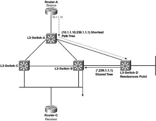
EAN: 2147483647
Pages: 135
- ERP Systems Impact on Organizations
- The Effects of an Enterprise Resource Planning System (ERP) Implementation on Job Characteristics – A Study using the Hackman and Oldham Job Characteristics Model
- Distributed Data Warehouse for Geo-spatial Services
- Relevance and Micro-Relevance for the Professional as Determinants of IT-Diffusion and IT-Use in Healthcare
- Development of Interactive Web Sites to Enhance Police/Community Relations