Scenario 3-2: Configuring Trunking Between Switches
| Trunks are an essential part of any switched network and allow a set of distributed switches to appear as a single switching fabric. By implementing trunks, users within the same VLAN can be connected to different switches, with the trunks carrying intra-VLAN traffic across the distributed switch network. Trunks can also be used to connect to end devices such as routers or servers, providing connectivity to multiple VLANs without the need for multiple physical network interfaces. Trunks and distributed VLANs can be very flexible; devices are not constrained to physical switches to ensure that they are connected to the correct VLAN, which allows for devices to be easily moved between physical switches while still maintaining connectivity to the VLAN that the device is supposed to belong to. In a sense, trunks and distributed VLANs provide "virtual cabling." On the flip side, trunks and distributed VLANs also introduce extra complexity in the network and can be difficult to troubleshoot if planned poorly, so they should be used only with careful planning and only where required. In this scenario, you will continue working on the topology from the last scenario, learning how to configure trunking between Switch-A and Switch-B. Configuration TasksBefore configuring a trunk, ensure that the appropriate VTP and VLAN configuration is in place. Trunks enable VTP communicationwhich are essentially control plane communications for VLANsbecause VTP advertisements are forwarded only across trunks. Once VTP has distributed the appropriate VLAN configuration to each switch, ports can be placed into the appropriate VLANs and data forwarding can begin. If you are not using VTP, you need to ensure that each switch in the network is configured with the appropriate VLAN information, and you need to do this to manually define the list of VLANs that are transported across each trunk. You don't necessarily need to have VTP and VLAN configurations in place before creating trunks; for example, in Scenario 3-1, a trunk actually formed between Switch-A and Switch-B before any VTP and VLAN configurations were in place, because of the default DTP modes configured on each switch. Assuming the appropriate VTP and VLAN configuration parameters are in place or are to be configured after configuring trunks, the following lists the configuration tasks required to configure a trunk:
Configuring Trunk EncapsulationOn Ethernet networks, you have two options for trunk encapsulation:
Your choice may be limited by the capabilities of the switch you are using. Table 3-2 describes trunking support on Cisco Catalyst switches.
For example, referring to Table 3-2 the Catalyst 2950 and 4000 series switches support only 802.1Q encapsulation, while the Catalyst 3550 series switches support both 802.1Q and ISL encapsulation. In this scenario, both Switch-A (Catalyst 3550) and Switch-B (Catalyst 6000) support both ISL and 802.1Q, so the encapsulation can be left as the default setting of negotiate. In this scenario, you configure the trunk to become an 802.1Q trunk. On switches that support both ISL and 802.1Q trunking, DTP can be used to negotiate the appropriate trunking encapsulation. When negotiation is configured, ISL is always preferred, with 802.1Q being negotiated only if either side of the trunk does not support ISL. If possible, try to use 802.1Q trunks. 802.1Q is standards-based and is now widely adopted by many vendors. Restrictions of the original 802.1Q standard (e.g., a single spanning-tree instance per Layer 2 networksee Chapter 4) have been overcome by Cisco. Native VLAN ConsiderationsIf you use 802.1Q trunks, you must ensure that you choose a common native VLAN for each port in the trunk. Failure to do this causes Cisco switches to partially shut down the trunk port because having mismatched native VLANs can result in spanning-tree loops. Native VLAN mismatches are detected via spanning tree and Cisco Discovery Protocol (CDP), not via DTP messages. If spanning tree detects a native VLAN mismatch, spanning tree blocks local native VLAN traffic and the remote switch native VLAN traffic on the trunk; however, the trunk still remains up for other VLANs. Many people often ask, "What should I configure as the native VLAN?" The answer to this question is based upon two important considerations:
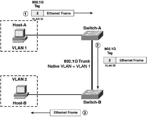
The native VLAN has importance on Cisco Catalyst switches for control protocols, namely DTP and spanning tree. DTP messages are always sent on the native VLAN, and spanning-tree bridge protocol data units (BPDUs) are also sent untagged on the native VLAN, which ensures interoperability with other switch vendors. Because some interswitch control communications rely on the native VLAN, it is recommended that you forward no user data on the native VLAN (i.e., create VLANs separate from the native VLAN for user devices). NOTE The 802.1Q specification states that only one spanning-tree instance should exist for a Layer 2 network, regardless of the number of VLANs. This instance runs on the native VLAN and is referred to as the Common Spanning Tree (CST) instance. Cisco Catalyst switches operate a single spanning-tree instance per VLAN, which is important in redundant Layer 2 topologies. To ensure interoperability with other switches that only support a single spanning-tree instance on the native VLAN, Cisco switches operate the CST instance on the native VLAN. If you are connecting 802.1Q trunks to switches from other vendors, it is recommended that you leave the native VLAN as VLAN 1 because many of these switches only support VLAN 1 as the native VLAN. The second consideration in configuring your native VLAN is security. The SANS Institute, an independent security research organization that provides authoritative information on security vulnerabilities, has published a vulnerability at www.sans.org/newlook/resources/IDFAQ/vlan.htm that outlines how the native VLAN on 802.1Q trunks can be used to gain access to destination devices in a VLAN different from the VLAN that a source device is located in (referred to as VLAN hopping). Figure 3-12 demonstrates how VLAN hopping works. Figure 3-12. 802.1Q VLAN Hopping
In Figure 3-12, the following events occur:
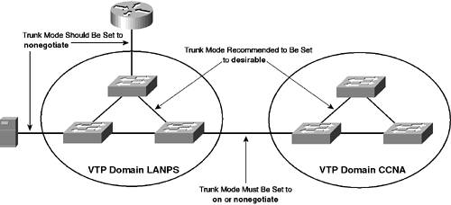
The vulnerability in the sequence of events described in Figure 3-12 is related to the fact that the sending device (Host-A) is located in the same VLAN as the native VLAN. If Host-A were in a different VLAN (e.g., VLAN 10), Switch-A would interpret the frame sent by Host-A as coming from VLAN 10, and when it came to forwarding the frame out the 802.1Q trunk, it would overwrite the 802.1Q header generated by Host-A with a new header indicating the frame belongs to VLAN 10. Because of this vulnerability, you need to ensure that the native VLAN used on 802.1Q trunks is not used by user devices (i.e., not assigned to any ports other than trunk ports). This arrangement ensures that user devices that attach to switches are never in the same VLAN as the native VLAN and cannot use the VLAN hopping vulnerability to breach the security of the network. In summary, most organizations typically leave the default setting of VLAN 1 as the native VLAN and ensure that all user devices are placed on other VLANs. Taking this approach ensures interoperability with other switch vendors if required and also mitigates the VLAN hopping security vulnerability. NOTE In this scenario, VLAN 10 is configured as the native VLAN, with the management interfaces for Switch-A and Switch-B placed in this VLAN. As per the security recommendations above, this configuration is not recommended (the management interface of network devices should also be considered a user device). A better configuration would be to place the management interfaces of Switch-A and Switch-B in VLAN 1; however, for the purposes of demonstrating VLAN 1 trunk clearing (discussed later in this scenario), VLAN 10 is used instead. Configuring Trunk Mode (DTP)Trunk mode determines how a trunk port attempts to negotiate a trunk. You can configure a switch port to dynamically negotiate a trunk based upon the port capabilities of each end of the trunk, or you can configure a port to always form a trunk, regardless of the configuration of the remote switch. The recommended trunk mode to use for interswitch links (trunks that connect two switches together) is desirable mode, because this mode allows a trunk port to actively negotiate a trunk with both sides of the trunk supporting DTP. In desirable mode, the switch sends the locally configured VTP domain name, trunking mode, and supported encapsulations to the remote switch. This information ensures a trunk forms only if the VTP domain names match and the trunking capabilities are compatible. An exception to this restriction is if a remote switch has no VTP domain defined (i.e., the switch has a blank configuration) and the local switch has a VTP domain defined. In this situation, both switches form a trunk. NOTE A trunk operating in a DTP mode of auto also sends VTP domain name information. If you configure the trunking mode to on, a switch can incorrectly force an interface to a trunking state while the remote switch has not formed a trunking state. By using a trunking mode of desirable, you can always be assured that a trunk has properly formed on both sides if one side reports that it has formed a trunk. If you need to connect switches that belong to different VTP domains via a trunk, you cannot use desirable mode because each switch detects different VTP domains and stops the trunk from forming. In this situation, configure a DTP mode of on or nonegotiate because a trunk interface configured in on mode does not send the VTP domain during DTP negotiation. It sends only the configured DTP mode and supported trunk encapsulations (a trunk mode of nonegotiate disables the sending of any DTP frames whatsoever). On trunks that connect to devices that don't use DTP (e.g., routers or servers), always configure a trunk to use the nonegotiate mode because this forces trunking without the use of any DTP whatsoever. Figure 3-13 indicates the appropriate trunking modes that should be configured between various network devices. Figure 3-13. Recommended Trunking Modes
Table 3-3 shows a matrix of the various modes and how the combination of each mode at either end of the link determines whether or not a trunk is formed.
Table 3-3 shows each the resulting trunk states that are reached based upon each combination of local and remote trunking mode. For example, if the local mode is set to auto and the remote mode is set to auto, both ends reach a non-trunk state because neither side actively attempts to negotiate. Determining the VLANs Enabled on Each TrunkBy default, a trunk transports traffic from all active VLANs. This arrangement can waste precious bandwidth on links to switches that do not service any directly connected or downstream devices within specific VLANs. When you design your network, map out the VLANs that are to be serviced throughout the network. This mapping allows you to determine which VLANs require service over the various trunks in the network. A well-designed Layer 2 network limits large numbers of VLANs being serviced near the edge of the network as much as possible, reducing the amount of VLAN traffic on trunks at the edge of the network. Once you have determined which VLANs you wish to transport over a trunk, you then have two options to actually implement the configuration:
Manual configuration requires you to configure each trunk port with the appropriate list of VLANs to service, ensuring that each end point of a trunk has an identical VLAN list. In a network that contains hundreds of trunks, this manual configuration becomes tiresome and prone to error. The other option, VTP pruning, automates the process dynamically. If used, VTP pruning should be enabled on all switches within a VTP domain. Notice in Figure 3-11 that no devices are connected to VLAN 4 on Switch-B. This configuration means that traffic for VLAN 4 does not need to be sent over the trunk between Switch-A and Switch-B Hence, VLAN 4 can be removed manually from the trunk, or VTP pruning can be enabled to dynamically remove the VLAN. In this scenario, you learn how to manually configure the allowed VLAN list on the trunk between Switch-A and Switch-B. NOTE Configuring VTP pruning and the rationale of manually configuring the allowed VLANs on a trunk versus using VTP pruning are explained further in Scenario 3-3. VLAN 1 ConsiderationsVLAN 1 is the default VLAN configured on Cisco Catalyst switches (and switches from other vendors) and has special significance. On Cisco Catalyst switches, you cannot fully remove VLAN 1 from a trunk, even if you are not using it in your network. This characteristic exists because Cisco Catalyst switches always use VLAN 1 for control communications. VLAN 1 is used for the following control protocols on Cisco Catalyst switches:
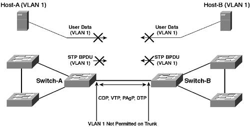
NOTE DTP messages are always sent on VLAN 1 for ISL trunks. For 802.1Q trunks, DTP messages are always sent on the native VLAN. It is important to understand that even if the native VLAN of an 802.1Q trunk is not VLAN 1, all of the above protocols (with the exception of DTP as indicated in the previous note) are still sent on VLAN 1, with a tag attached indicating VLAN 1 is not the native VLAN (if the native VLAN is VLAN 1, then messages are sent without a tag). Because of the reliance of important Cisco Catalyst control protocols on VLAN 1, many low-end and older Cisco Catalyst switches do not allow you to clear VLAN 1 from a trunk. This restriction means that VLAN 1 traffic is propagated throughout the network, which is normally not a problem because Cisco recommends that VLAN 1 not be configured as a user VLAN. Hence, the volumes of traffic in VLAN 1 are very small. The problem with extending VLAN 1 throughout the network comes to play in larger switched networks where a spanning-tree instance for VLAN 1 must operate throughout the entire switched network. Finite limits exist for the network diameter of spanning-tree topologies (in Chapter 4, you learn that the maximum recommended network diameter of a spanning-tree topology is seven switches). Thus, extending VLAN 1 throughout a large switched network can lead to network instability. NOTE Cisco recommends you do not have VLANs that span the entire switched topology for large switched networks. Clearing VLANs from trunks is one approach to guard against such a span; however, Cisco recommends that you use a multilayer topology (discussed in Chapter 6, "Layer 3 Switching") to reduce the size of Layer 2 networks into smaller, more stable, and manageable chunks. In newer Cisco Catalyst switches, you can clear VLAN 1 partially from a trunk. This feature is known as VLAN 1 disable on trunk and does not actually fully remove VLAN 1 traffic from the trunk. NOTE You can clear VLAN 1 from a trunk from CatOS 5.4 onwards on any CatOS-based switch. Prior to this release, you could not clear VLAN 1 from a trunk on a CatOS-based switch. The Cisco IOS-based Catalyst 2900XL/3500XL switches do not allow you to clear VLAN 1 from a trunk; however, the Catalyst 2950/3550, Cisco IOS 4000/4500, and native IOS 6000/6500 switches allow you to clear VLAN 1. So what then is cleared from VLAN 1? Two important types of traffic are cleared from VLAN 1. The first is user data, meaning if, for example, you have users on Switch-A in VLAN 1 and users in Switch-B in VLAN 1, users cannot communicate if VLAN 1 is cleared from a trunk between Switch-A and Switch-B. The second type of traffic that is cleared is spanning-tree BDPU traffic, which is the important feature of VLAN 1 trunk clearing. Clearing VLAN 1 from a trunk reduces the size of the VLAN 1 spanning-tree domain, which allows network designers to control the extent of the VLAN 1 spanning-tree topology and ensures the stability of larger networks. Figure 3-14 demonstrates what happens when VLAN 1 is cleared from a trunk. Figure 3-14. Clearing VLAN 1 from a Trunk
In Figure 3-14, VLAN 1 on the trunk between Switch-A and Switch-B has been cleared, which means that only VTP, CDP, PAgP, and VTP control communications are permitted across the trunk. All other communications, including spanning-tree BPDUs and user data, are blocked. NOTE The topology of Figure 3-14 is not recommended. You should never partition the same VLAN into two separate pieces because such a separation may cause problems with your Layer 3 protocols that operate on top of the VLAN. If you are clearing trunks from a VLAN, ensure that the VLAN is a single entity that is not partitioned within the network. Configuration TasksThis scenario is based upon the topology of Figure 3-11 and assumes the following configurations have already been implemented:
Assuming the above configurations are in place, configuration of trunks for this scenario involves the following tasks:
Configuring Interswitch TrunksIn Figure 3-11, an interswitch trunk exists between Switch-A (Cisco IOS) and Switch-B (CatOS). The configuration on each of these switches is now examined in separate sections specific to the operating system on each. Cisco IOS ConfigurationOn Cisco IOS, the switchport mode, switchport nonegotiate, and switchport trunk interface configuration commands are used to configure trunks. The switchport mode command is used to configure the DTP mode that the trunk interface operates in and has the following syntax: Switch(config-if)# switchport mode {access | dot1q-tunnel | dynamic {auto | desirable} | trunk} If the access keyword is specified, then the interface is configured as an access port and trunking is disabled, which is equivalent to the DTP mode of off. If the dynamic keyword is specified, a DTP mode of auto or desirable can be selected by configuring the appropriate keyword. By default, all interfaces are configured to operate in a DTP mode of desirable, i.e., switchport mode dynamic desirable. Finally, if the trunk keyword is specified, this forces the interface to trunk unconditionally, which is equivalent to a DTP mode of on. If the trunk keyword is specified, you can also optionally use the switchport nonegotiate interface configuration command to force the DTP mode for the interface to nonegotiate. Switch(config-if)# switchport nonegotiate Table 3-4 describes each of the various options for configuring the switchport mode and switchport nonegotiate commands and how these affect the trunking mode of the interface on Cisco IOS Catalyst switches.
NOTE When configuring a trunk mode of on or nonegotiate, you must explicitly configure the trunk encapsulation as ISL or 802.1Q. By default, if a Cisco IOS Catalyst switch supports both 802.1Q and ISL, the trunk encapsulation is set to negotiate, which must be disabled if you wish to configure a trunk mode of on or nonegotiate. The recommended trunking mode is desirable, because this mode ensures that the trunk forms only if both sides of the trunk are compatible. Another recommendation is that you disable DTP on all switch ports that are to operate as access ports. This configuration removes DTP negotiation timeout delays of between 5-10 seconds that occur when a port first initializes. Configuring a DTP mode of off ensures access ports do not have to wait for this period, speeding up the time it takes for an access port to transition to a state where it is actively forwarding data. Once the appropriate DTP mode has been configured, the switchport trunk interface configuration command is used to configure the various remaining trunking parameters. This command has the following syntax: Switch(config-if)# switchport trunk {allowed vlan vlan-list} | {encapsulation {dot1q | isl | negotiate}} | {native vlan vlan-id} | {pruning vlan vlan-list}
In this scenario, an 802.1Q trunk is required between Switch-A and Switch-B, which at most needs to transport only VLANs 1, 2, 3, 4, and 10, because these are the only VLANs in the network. Using Cisco recommendations, a DTP mode of desirable should be configured on both Switch-A and Switch-B. An ISL trunk also needs to be configured between Switch-A and Router-A, and requires a DTP mode of nonegotiate on Switch-A because Cisco IOS routers do not support DTP. All access ports (non-trunk ports) also should have a DTP mode of off configured to reduce port initialization delays associated with DTP negotiation. In terms of the VLANs that need to be transported across the trunk between Switch-A and Switch-B, only VLANs 2, 3, 5, and 10 are required, which means that VLAN 1 and VLAN 4 can be cleared from the trunk. In this scenario, you manually clear VLAN 1 from the trunk. In Scenario 2-3, you clear VLAN 4 from the trunk using VTP pruning. NOTE You cannot use VTP pruning to clear VLAN 1 from a trunk, which means you must manually remove VLAN 1 from the allowed VLAN list for a trunk. The native VLAN should also be changed to a VLAN that is not used for user devices to bypass the VLAN hopping security vulnerability of 802.1Q trunking. In this scenario because VLAN 1 is not being used for user devices, it can be used as the native VLAN. However, to demonstrate how to configure a different native VLAN other than the default VLAN 1, VLAN 10 is to be configured as the native VLAN, which is also not used for user devices. Example 3-10 demonstrates the trunking configuration required on Switch-A. Example 3-97. Configuring Trunking on Switch-ASwitch-A# configure terminal Switch-A(config)# interface fastEthernet0/1 Switch-A(config-if)# switchport trunk encapsulation dot1q Switch-A(config-if)# switchport mode dynamic desirable Switch-A(config-if)# switchport trunk native vlan 10 Switch-A(config-if)# switchport trunk allowed vlan 2-5,10,1002-1005 In Example 3-10, the trunk encapsulation is configured as 802.1Q (the default setting is to negotiate), and the trunk mode is set to desirable (this is the default setting, but is shown for demonstration purposes). Finally, the allowed VLAN list is set to VLANs 2-5, VLAN 10, and VLANs 1002 to 1005. This allowed VLAN list has cleared VLAN 1 from the trunk so that only control communications that require VLAN 1 (VTP, PAgP, and CDP) operate across the trunk. NOTE On the Catalyst 2900XL/3500XL and Catalyst 2950/3550 switches, VLANs 1002 to 1005 must always be transported across a trunk. For 802.1Q trunks, the native VLAN should also be enabled on the trunk. VLANs 1002 to 1005 are special VLANs used to represent Token Ring and Fiber Distributed Data Interface (FDDI) VLANs. On Cisco IOS-based Catalyst 4000/4500 and Catalyst 6000/6500 switches, you can remove all VLANs from a trunk. During the configuration of Example 3-10, you may notice the following error messages are displayed on the console: %SPANTREE-2-RECV_PVID_ERR: Received BPDU with inconsistent peer vlan id 1 on FastEthernet0/1 VLAN10. 00:10:56: %SPANTREE-2-BLOCK_PVID_PEER: Blocking FastEthernet0/1 on VLAN0001.
00:10:56: %SPANTREE-2-BLOCK_PVID_LOCAL: Blocking FastEthernet0/1 on VLAN0010.
These errors are generated because the native VLAN is not matched on Switch-A and Switch-B (the native VLAN on Switch-B is currently the default setting, which is VLAN 1). The errors indicate that spanning tree has detected mismatched native VLANs and has shut down VLAN 1 and VLAN 10 on the trunk. Once you have configured a trunk, you can use the show interface switchport command to verify your configuration, as demonstrated on Switch-A in Example 3-11. Example 3-98. Verifying Trunking on Switch-ASwitch-A# show interface FastEthernet0/1 switchport Name: Fa0/1 Switchport: Enabled Administrative Mode: dynamic desirable Operational Mode: trunk Administrative Trunking Encapsulation: dot1q Operational Trunking Encapsulation: dot1q Negotiation of Trunking: On Access Mode VLAN: 1 (default) Trunking Native Mode VLAN: 10 (Native) Administrative private-vlan host-association: none Administrative private-vlan mapping: none Operational private-vlan: none Trunking VLANs Enabled: 2-5,10,1002-1005 Pruning VLANs Enabled: 2-1001 Protected: false Unknown unicast blocked: disabled Unknown multicast blocked: disabled Voice VLAN: none (Inactive) Appliance trust: none In Example 3-11, notice that two types of state are describedadministrative and operational. Administrative state refers to how the interface is configured, while operational state refers to how the interface is currently operating. For example, the administrative mode is dynamic desirable because this is how the interface was configured in Example 3-10. Notice that the operational mode is trunk, which indicates the interface is currently trunking. Although Switch-B has not yet been configured for trunking, because ports on CatOS-based Catalyst switches are configuring with a trunk mode or auto by default and the VTP domain names are matching (as previously configured in Scenario 3-1), a trunk has formed. You can also use the show interface trunk command to verify the trunking configuration and status of each trunk interface, as demonstrated on Switch-A in Example 3-12. Example 3-99. Verifying Trunking on Switch-ASwitch-A# show interface trunk Port Mode Encapsulation Status Native vlan Fa0/1 desirable 802.1q trunking 10 Port Vlans allowed on trunk Fa0/1 2-5,10,1002-1005 Port Vlans allowed and active in management domain Fa0/1 2-5,10 Port Vlans in spanning tree forwarding state and not pruned Fa0/1 2-5 Notice on the last shaded line that only traffic for VLANs 2-5 is being forwarded on the trunk. Spanning tree has blocked VLAN 10 on the trunk due to the native VLAN mismatch currently present. NOTE Spanning tree also blocks the native VLAN configured on the remote switch on the trunk. In this scenario, this native VLAN is VLAN 1 because Switch-B has not yet been configured and the default native VLAN is VLAN 1. In Example 3-12, VLAN 1 is not included in any of the allowed VLAN lists because it has been manually cleared from the trunk (see Example 3-10). If VLAN 1 had not been cleared from the trunk, you would see VLAN 1 in the "Vlans allowed on trunk" column, but not in the "Vlans in spanning tree forwarding state…" column, due to spanning tree blocking VLAN 1 due to the native VLAN mismatch. CatOS ConfigurationOn CatOS, the set trunk and set vlan commands are used to configure trunks. The set trunk command is used to configure the following parameters of a trunk port:
The following shows the syntax for this command when configuring the trunk mode and encapsulation: Console> (enable) set trunk module/port [on | off | auto | desirable | nonegotiate] [dot1q | isl | negotiate] NOTE The default trunking mode on CatOS is auto, and the default trunking encapsulation is to negotiate if multiple encapsulations are supported. The following shows the syntax for this command when configuring the VLANs that are allowed to trunk: Console> (enable) set trunk module/port vlan-list When configuring the allowed VLAN list, the set trunk command is incremental, meaning it adds VLANs to the allowed VLAN list rather than overwriting the previous VLAN list. You must explicitly remove unwanted VLANs from the allowed VLAN list, using the clear trunk command: Console> (enable) clear trunk module/port vlan-list Because you normally want to specify a small number of VLANs in the allowed VLAN list, it is easiest to clear all VLANs from a trunk and then use the set trunk command to configure the specific VLANs allowed on the trunk. Finally, the set vlan command is used to configure the native VLAN for 802.1Q trunks: Console> (enable) set vlan vlan-id module/port Unlike Cisco IOS, which has separate commands for assigning the VLAN for an access port and the native VLAN for a trunk port, CatOS uses the access port VLAN configuration to determine the native VLAN for 802.1Q trunks. For this scenario, the trunk to Switch-A has already been configured on Switch-A as an 802.1Q trunk, with a trunking mode of desirable and an allowed VLAN list of 2-5, 10, and 1002-1005. The native VLAN must also be set to VLAN 10. Example 3-13 demonstrates configuring these parameters on Switch-B to ensure correct trunk operation with Switch-A. Example 3-100. Configuring Trunking on Switch-BSwitch-B> (enable) set trunk 2/1 desirable dot1q Port(s) 2/1 trunk mode set to desirable. Port(s) 2/1 trunk type set to dot1q. Switch-B> (enable) clear trunk 2/1 1-1005,1025-4094 Removing Vlan(s) 1-1005,1025-4094 from allowed list. Port 2/1 allowed vlans modified to . Switch-B> (enable) set trunk 2/1 2-5,10 Adding vlans 2-5,10 to allowed list. Port(s) 2/1 allowed vlans modified to 2-5,10. Switch-B> (enable) set vlan 10 2/1 VLAN 10 modified. VLAN 1 modified. VLAN Mod/Ports ---- ----------------------- 10 2/1 Notice on Switch-B that VLAN 1 is manually cleared from the trunk. Also, notice that you don't need to include VLANs 1002-1005 in the allowed VLAN list, unlike Switch-A, which requires these VLANs. NOTE After the native VLAN is configured as VLAN 10 on Switch-B, spanning tree on both switches detects that the native VLANs are matched and unblocks any previously blocked VLANs on the trunk port. Once you have configured a trunk, you should verify your configuration using the show trunk command. Example 3-14 demonstrates the use of the show trunk command on Switch-B. Example 3-101. Verifying Trunking on Switch-BSwitch-B> (enable) show trunk * - indicates vtp domain mismatch Port Mode Encapsulation Status Native vlan -------- ----------- ------------- ------------ ----------- 2/1 desirable dot1q trunking 10 Port Vlans allowed on trunk -------- --------------------------------------------------------------------- 2/1 2-5,10 Port Vlans allowed and active in management domain -------- --------------------------------------------------------------------- 2/1 2-5,10 Port Vlans in spanning tree forwarding state and not pruned -------- --------------------------------------------------------------------- 2/1 2-5,10 Each of the shaded lines verifies the configuration of the trunk port in Example 3-13. At this point, the real test is to ensure devices within each VLAN can communicate with each other. For example, Switch-A and Switch-B should be able to ping each other because VLAN 5 is forwarded across the trunk. Similarly, Host-B should be able to communicate with Host-D, and Host-C should be able to communicate with Host-E because VLAN 2 and VLAN 3 respectively are forwarded across the trunk. Verifying TrunkingYou can verify trunking operation using the various show commands described in the previous section. You can also verify trunking operation by monitoring trunking operation, which provides detailed low-level information that aids in troubleshooting problems. On Cisco IOS, you can use the debug dtp command with various options to view DTP trunking events or errors as they occur. Example 3-15 shows a sample output of a trunk being established with the debug dtp packets command enabled. Example 3-102. Debugging DTP Packets on a Cisco IOS SwitchSwitch-A# debug dtp packets DTP packet processing debugging is on ! The first DTP frame is sent by Switch-A. The TOS indicates the trunk ! operational status of the interface, which is currently an access interface ! as no trunk has formed ! The TAS indicates the trunk administrative status, which is DESIRABLE as this ! is the DTP mode configured for the port ! THE TOT/TAT similarly describe the operational and administrative trunk ! encapsulation, which is 802.1Q 03:27:02: DTP-pkt:Fa0/1:Sending packet ../dyntrk/dyntrk_process.c:1183 03:27:02: DTP-pkt:Fa0/1: TOS/TAS = ACCESS/DESIRABLE ../dyntrk/dyntrk_process.c:1186 03:27:02: DTP-pkt:Fa0/1: TOT/TAT = 802.1Q/802.1Q ../dyntrk/dyntrk_process.c:1189 03:27:02: DTP-pkt:Fa0/1:datagram_out ../dyntrk/dyntrk_process.c:1221 03:27:02: DTP-pkt:Fa0/1:datagram_out encap ../dyntrk/dyntrk_process.c:1233 03:27:02: DTP-pkt:Fa0/1:Invalid TLV (type 0, len 0) in received packet. ../dyntrk/dyntrk_core.c:1266 ! An initial DTP frame is received from Switch-B, which includes the VTP domain, ! trunk mode and trunk encapsulation 03:27:02: DTP-pkt:Fa0/1:Good DTP packet received: ../dyntrk/dyntrk_core.c:1401 03:27:02: DTP-pkt:Fa0/1: Domain: LANPS ../dyntrk/dyntrk_core.c:1404 03:27:02: DTP-pkt:Fa0/1: Status: TOS/TAS = ACCESS/DESIRABLE ../dyntrk/dyntrk_core.c:1407 03:27:02: DTP-pkt:Fa0/1: Type: TOT/TAT = 802.1Q/802.1Q ../dyntrk/dyntrk_core.c:1409 03:27:02: DTP-pkt:Fa0/1: ID: 00507356C2F1 ../dyntrk/dyntrk_core.c:1412 ! Because the VTP domain, mode, and encapsulation are compatible with Switch-A, ! a DTP frame is sent, this time to indicate that operation state (TOS) is TRUNK, ! indicating Switch-A is moving to a trunking status 03:27:03: DTP-pkt:Fa0/1:Sending packet ../dyntrk/dyntrk_process.c:1183 03:27:03: DTP-pkt:Fa0/1: TOS/TAS = TRUNK/DESIRABLE ../dyntrk/dyntrk_process.c:1186 03:27:03: DTP-pkt:Fa0/1: TOT/TAT = 802.1Q/802.1Q ../dyntrk/dyntrk_process.c:1189 03:27:03: DTP-pkt:Fa0/1:datagram_out ../dyntrk/dyntrk_process.c:1221 03:27:03: DTP-pkt:Fa0/1:datagram_out encap ../dyntrk/dyntrk_process.c:1233 03:27:04: DTP-pkt:Fa0/1:Invalid TLV (type 0, len 0) in received packet. ../dyntrk/dyntrk_core.c:1266 ! Switch-B sends responds with a DTP frame, which includes a TOS of TRUNK, ! indicating the port on Switch-B is also trunking 03:27:04: DTP-pkt:Fa0/1:Good DTP packet received: ../dyntrk/dyntrk_core.c:1401 03:27:04: DTP-pkt:Fa0/1: Domain: LANPS ../dyntrk/dyntrk_core.c:1404 03:27:04: DTP-pkt:Fa0/1: Status: TOS/TAS = TRUNK/DESIRABLE ../dyntrk/dyntrk_core.c:1407 03:27:04: DTP-pkt:Fa0/1: Type: TOT/TAT = 802.1Q/802.1Q ../dyntrk/dyntrk_core.c:1409 03:27:04: DTP-pkt:Fa0/1: ID: 00507356C2F1 ../dyntrk/dyntrk_core.c:1412 ! Both switches have indicate a trunk operational status (TOS) of TRUNK, ! so the interface changes its Layer 2 status to UP ! DTP negotiation is complete 03:27:04: %LINK-3-UPDOWN: Interface FastEthernet0/1, changed state to up ... ... In Example 3-15, you can see DTP packets being exchanged between the local and remote switch. Notice that DTP packets include the VTP domain (LANPS), which is why you must configure the same VTP domain name if you wish to negotiate a trunk. During trunk negotiation, DTP frames are sent every second; after successful negotiation, DTP frames are send every 30 seconds. On CatOS switches, trunking can be monitored by setting a low SYSLOG severity level for the DTP facility and viewing SYSLOG messages as they are generated. Example 3-16 shows how to configure Switch-B to display all DTP SYSLOG events as they are generated. Example 3-103. Enabling All SYSLOG DTP Events for Switch-BSwitch-B> (enable) set logging level dtp 7 System logging facility <dtp> for this session set to severity 7(debugging) Switch-B> (enable) set logging console enable System logging messages will be sent to the console. %DTP-5-NONTRUNKPORTON:Port 2/1 has become non-trunk %DTP-5-TRUNKPORTON:Port 2/1 has become dot1q trunk In Example 3-16, you enable logging of all DTP events to the console, because the lowest severity level is configured. Port 2/1 is then disconnected and reconnected, and you can see the resulting SYSLOG event messages. | ||||||||||||||||||||||||||||||||||||||||||||||||||||||||||||||||||||||||||||||||||||||||
EAN: 2147483647
Pages: 135