Scenario 3-3: VTP Pruning
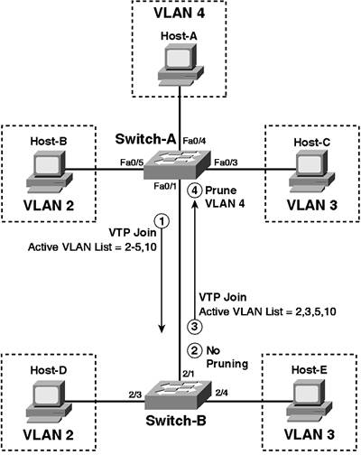
| In the previous scenario, the list of allowed VLANs is configured manually. This configuration is static, which means that if you need to enable a previously disallowed VLAN on a trunk, you must do so manually. In environments where users from different VLANs move around a lot, having to reconfigure the allowed VLAN list each time a user moves clearly starts to become tiresome and prone to error. VTP pruning offers a dynamic mechanism that automatically configures the allowed VLAN lists on trunks within a VTP domain. Based upon whether or not a switch has ports currently active within a VLAN, the switch dynamically indicates to the remote switch on the other side of a trunk that the traffic within the inactive VLAN not be forwarded across a trunk. The mechanism used by VTP to allow the communication of VTP pruning information is known as the VTP Join message. A VTP Join message includes a list of the VLANs that are currently active on the switch. Figure 3-15 demonstrates how VTP Join messages are used to prune trunks in the topology of Figure 3-11. Figure 3-15. VTP Join Messages and VTP Pruning
In Figure 3-15, the allowed VLAN list on both switches is VLANs 2-5 and VLAN 10, as configured in the previous scenario. Switch-A and Switch-B determine which VLANs are active within this the allowed VLAN list for the trunk and then send this list in VTP Joins to the remote switch. The native VLAN of the trunk in Figure 3-15 is VLAN 10; hence, VLAN 10 must also be transported across the trunk. Both of the management interfaces for the switches are in VLAN 5; hence, VLAN 5 must also be transported across the trunk. On Switch-A, notice that user VLANs 2-4 are active, which means that the active list of VLANs on Switch-A for the trunk is VLANs 2-5 and VLAN 10. The VTP Join message sent from Switch-A to Switch-B (Step 1) includes this list of active VLANs. When Switch-B receives the VTP Join (Step 2), it does not prune any VLANs from the trunk, because all VLANs allowed on the trunk are listed in the VTP Join message. On Switch-B, notice that user VLANs 2 and 3 are active, while no users are attached to VLAN 4, which means that the active list of VLANs on Switch-B for the trunk is VLANs 2, 3, 5, and 10. The VTP Join message sent from Switch-B to Switch-A (Step 3), therefore, excludes VLAN 4 from the active list and Switch-A consequently prunes VLAN 4 from the trunk (Step 4). To use VTP pruning, the feature must be enabled on all VTP servers and clients in the network (by default, VTP pruning is disabled). Fortunately, VTP pruning can be learned by VTP clients, meaning once you enable VTP pruning on VTP servers, each VTP client automatically enables VTP pruning. Of course, you might not want VTP pruning enabled on some VLANs. The classic example is VLAN 1, which Cisco Catalyst switches automatically ensure is not available for VTP pruning. If a VLAN is eligible for pruning, it is said to be prune eligible. By default, all VLANs on a Cisco Catalyst switches are prune eligible, except for VLAN 1. Cisco Catalyst switches can be configured with a custom prune eligible list, which ensures specific VLANs are never pruned from a trunk. Configuration TasksTo configure VTP pruning, the following configuration tasks are required:
Enabling VTP PruningAs previously indicated, VTP pruning needs to be enabled only on VTP servers, after which all VTP clients in the VTP domain automatically enable VTP pruning. VTP pruning can be enabled only on switches running in VTP server mode. If a switch is running in VTP client mode, an error is displayed. To enable VTP pruning on a Cisco IOS switch, you use the vtp pruning VLAN configuration or global configuration command. Example 3-17 demonstrates enabling VTP pruning on Switch-A. Example 3-104. Enabling VTP Pruning on Switch-ASwitch-A# configure terminal Switch-A(config)# vtp pruning Pruning switched on On CatOS, the set vtp pruning command is used to enable or disable VTP pruning. Console> (enable) set vtp pruning {enable | disable} Because Switch-B is a VTP client, you cannot enable VTP pruning explicitly on Switch-B without changing the VTP mode to server. However, you do not need to enable VTP pruning on Switch-B because it automatically inherits the VTP pruning configuration from Switch-A. Configuring the Prune Eligible ListOnce VTP pruning is enabled, you can optionally configure a prune eligible list if you wish to restrict the VLANs that can be pruned. On Cisco IOS, the prune eligible list can be configured on a per-trunk basis, allowing for flexible configuration options. On CatOS, the prune eligible list is configured globally for all trunks. To configure the VTP prune list on Cisco IOS, you use the switchport trunk pruning interface configuration command on the trunk that you wish to configure. Switch(config-if)# switchport trunk pruning vlan vlan-list In Figure 3-11, VLAN 4 is only attached to Switch-A, and hence can be safely pruned from the trunk between Switch-A and Switch-B. In contrast, devices in VLANs 2 and 3 are attached to both switches, so these VLANs must be trunked in order for devices attached to different switches to communicate. VLAN 5 (used for management communications) and VLAN 10 (the native VLAN) are used for interswitch control communications, and thus, should never be pruned from the trunks. Example 3-18 demonstrates configuring a prune eligible list on Switch-A that permits only VLAN 4 to be pruned from the trunk to Switch-B. Example 3-105. Configuring a Prune Eligible List on Switch-ASwitch-A# configure terminal Switch-A(config)# interface fastEthernet0/1 Switch-A(config-if)# switchport trunk pruning vlan 4 To configure the VTP prune list on CatOS, you use the set vtp pruneeligible command. Console> (enable) set vtp pruneeligible vlan-list Just like the allowed VLAN list on CatOS, this command is additive in that it adds the VLANs configured in the vlan-list to the current prune eligible list instead of overriding the current list. By default, the prune eligible list includes VLANs 21000 on CatOS, which means that you must explicitly clear VLANs from the list using the clear vtp pruneeligible command if you do not want them to be on the prune eligible list. Console> (enable) clear vtp pruneeligible vlan-list Example 3-19 demonstrates configuring a prune eligible list on Switch-B that permits only VLAN 4 to be pruned from the trunk to Switch-A. Example 3-106. Configuring a Prune Eligible List on Switch-BSwitch-B> (enable) clear vtp pruneeligible 2-1005 Vlans 1-4094 will not be pruned on this device. VTP domain LANPS modified. Switch-B> (enable) set vtp pruneeligible 4 Vlan 4 eligible for pruning on this device. VTP domain LANPS modified. Notice in Example 3-19 that the prune eligible list is first totally cleared and then VLAN 4 is added to the prune eligible list. Verifying VTP PruningOnce VTP pruning has been enabled and any VLANs have been added or removed from the prune eligible list, verify that the VTP pruning configuration is actually working. This scenario assumes that in Figure 3-11, Host-A has been connected to interface Fa0/4 on Switch-A and that interface Fa0/4 has been placed into VLAN 4. This configuration means that VLAN 4 is inactive on Switch-A. Each switch should detect this and will not send a VTP Join message for the inactive VLAN to the remote switch. For example, when Switch-B detects VLAN 4 is inactive on the switch, Switch-B does not include VLAN 4 in VTP Join messages sent to Switch-A, meaning Switch-A prunes VLAN 2 from the trunk, ensuring VLAN 2 traffic is not sent to Switch-B. To verify VTP pruning on Cisco IOS, use the show interface trunk command, which includes the list of VLANs in a forwarding state on each trunk interface. Example 3-20 demonstrates this command on Switch-A: Example 3-107. Verifying VTP Pruning on Switch-ASwitch-A# show interface trunk Port Mode Encapsulation Status Native vlan Fa0/1 desirable 802.1q trunking 10 Port Vlans allowed on trunk Fa0/1 2-5,10,1002-1005 Port Vlans allowed and active in management domain Fa0/1 2-5,10 Port Vlans in spanning tree forwarding state and not pruned Fa0/1 2,3,5,10 In Example 3-20, notice that VLANs 2-5 and 10 are active and allowed on the Fa0/1 trunk interface, as indicated by the first shaded line. The second shaded line indicates that VLAN 4 is currently pruned from the trunk because Switch-B has not included this VLAN in the VTP Join messages sent to Switch-A. TIP Do not be confused by the fact that the output in Example 3-20 indicates VLANs 2, 3, 5, and 10 are in a "spanning tree forwarding state." This statement is misleading because it implies that spanning-tree BPDUs for VLAN 4 are not sent across the trunk. In fact, spanning-tree BPDUs for all VLANs in the manually-configured allowed VLAN list are sent across the trunk, regardless of whether they have been pruned or not pruned. This fact means that VTP pruning is useful only for reducing the unnecessary propagation of user data within pruned VLANs across trunks, but does not reduce the size of the spanning-tree topology for pruned VLANs. To verify VTP pruning on CatOS, use the show trunk command, which includes the list of VLANS in a forwarding state on each trunk port. Example 3-21 demonstrates this command on Switch-B. Example 3-108. Verifying VTP Pruning on Switch-BSwitch-B> (enable) show trunk * - indicates vtp domain mismatch Port Mode Encapsulation Status Native vlan -------- ----------- ------------- ------------ ----------- 2/1 desirable dot1q trunking 10 Port Vlans allowed on trunk -------- --------------------------------------------------------------------- 2/1 2-5,10 Port Vlans allowed and active in management domain -------- --------------------------------------------------------------------- 2/1 2-5,10 Port Vlans in spanning tree forwarding state and not pruned -------- --------------------------------------------------------------------- 2/1 2-5,10 In Example 3-21, notice that the VLANs currently in a forwarding state are VLANs 2-5 and 10, which is identical to the manually configured allowed VLAN list. This is because all allowed VLANs are active on Switch-A, and hence are all included in VTP Join messages sent to Switch-B. |
EAN: 2147483647
Pages: 135