Configuration Problems
The problems encountered while configuring and installing RIP in a network are:
-
RIP routes are missing from the routing table.
-
RIP is not installing all possible equal-cost paths.
RIP Routes Missing from Routing Table
This condition arises due to a missing or misconfigured network statement. The most obvious area to check is the router configuration specific to routing, which also includes the network statement configuration.
When a network command is added to the routing configuration of the router, it performs these functions:
-
Activates the RIP routing engine and sends and receives the RIP routing updates.
-
Advertises in the routing update about the information regarding the connected interfaces and the IP address assigned to the network configured using the network command.
As a result, if the network command is missing or not configured properly, it will lead to inconsistency or missing routes in the routing table.
Consider a scenario in which Router4 (as shown in Figure 6.1) is unable to ping any IP address that belongs to networks 11.0.1.0 and 11.0.2.0. Any host (including router interfaces) belonging to networks 11.0.1.0 and 11.0.2.0 is unreachable from the Router4. This problem can arise due to two reasons:
-
Missing network command
-
Configuration of passive interface
Missing Network Command
As discussed earlier, when a network command is configured, it activates the router to send the routing updates to its neighboring routers. This can happen only if one or more interfaces belonging to the router are assigned the IP address that represents the configured network. The current state of the IP routing table of Router4 is shown in Listing 6.16.
Listing 6.16 Current State of the IP Routing Table of Router4
Router4#sh ip route Codes: C - connected, S - static, I - IGRP, R - RIP, M - mobile, B - BGP D - EIGRP, EX - EIGRP external, O - OSPF, IA - OSPF inter area E1 - OSPF external type 1, E2 - OSPF external type 2, E - EGP i - IS-IS, L1 - IS-IS level-1, L2 - IS-IS level-2, * - candidate default U - per-user static route Gateway of last resort is not set C 10.0.5.0/24 is directly connected, Loopback1 C 10.0.4.0/24 is directly connected, FastEthernet0/0 R 10.0.1.0/24 [120/1] via 10.0.4.1, 00:01:32, FastEthernet0/0 R 10.0.2.0/24 [120/1] via 10.0.4.1, 00:02:27, FastEthernet0/0 R 10.0.3.0/24 [120/1] via 10.0.4.1, 00:07:35, FastEthernet0/0 R 192.168.2.0/24 [120/1] via 10.0.4.1, 00:05:40, FastEthernet0/0 R 192.168.1.0/24 [120/2] via 10.0.4.1, 00:07:17, FastEthernet0/0
From the routing table in Listing 6.16, it is evident that Router4 does not have any knowledge about networks 11.0.1.0 and 11.0.2.0. This may happen when Router4 is not receiving routing updates from the mentioned networks from its connected neighbors. To check this, confirm whether or not Router1 is advertising the 11.0.0.0 networks in its routing update. Use the command show ip protocols to confirm the networks that are being advertised. Listing 6.17 shows the output of the command show ip protocols by Router1 (of Figure 6.1) in its routing update.
Listing 6.17 Output of the Command show ip protocols from Router1
Router1#sh ip protocols Routing Protocol is "rip" Sending updates every 30 seconds, next due in 21 seconds Invalid after 180 seconds, hold down 180, flushed after 240 Outgoing update filter list for all interfaces is Incoming update filter list for all interfaces is Redistributing: rip Default version control: send version 1, receive any version Interface Send Recv Key-chain FastEthernet0 1 1 2 Routing for Networks: 192.168.1.0 Routing Information Sources: 192.168.1.1 120 00:00:0 Distance: (default is 120)
From the Listing 6.17, it is clear that the RIP in Router1 is active only for network 192.168.1.0 and not for network 11.0.0.0. This problem occurs due to a missing network command. To resolve this, configure the router with the network command to start sending routing updates about the 11.0.0.0 network to the directly connected neighboring routers. The mentioned configuration for Router1 is shown in Listing 6.18.
Listing 6.18 Configuration for Router1
Router1#conf t Router1(global)#router rip Router1(global-router)#network 11.0.0.0
Once the router accepts the changes, recheck the configuration by using the commands show ip protocols in Router1 and show ip route in Router4.
The recheck of output of the command show ip protocols for Router1 is shown in Listing 6.19.
Listing 6.19 Recheck of Output of the Command show ip protocols for Router1
Router1#show ip protocols Routing Protocol is "rip" Sending updates every 30 seconds, next due in 21 seconds Invalid after 180 seconds, hold down 180, flushed after 240 Outgoing update filter list for all interfaces is Incoming update filter list for all interfaces is Redistributing: rip Default version control: send version 1, receive any version Interface Send Recv Key-chain FastEthernet0 1 1 2 Routing for Networks: 192.168.1.0 11.0.0.0 Routing Information Sources: 192.168.1.1 120 00:00:0 Distance: (default is 120)
As per the output of the command in Listing 6.19, it is clear that Router1 is now routing for networks 192.168.1.0 and 11.0.0.0. This output confirms that at least Router1 is now sending updates about network 11.0.0.0 to its connected routers. The next step would be to check whether Router4 has updated its routing table with a new entry about 11.0.0.0, as required. Listing 6.20 shows the output of the command show ip route for Router4.
Listing 6.20 Recheck of Output of the Command show ip route for Router4
Router4#sh ip route Codes: C - connected, S - static, I - IGRP, R - RIP, M - mobile, B - BGP D - EIGRP, EX - EIGRP external, O - OSPF, IA - OSPF inter area E1 - OSPF external type 1, E2 - OSPF external type 2, E - EGP i - IS-IS, L1 - IS-IS level-1, L2 - IS-IS level-2, * - candidate default U - per-user static route Gateway of last resort is not set C 10.0.5.0/24 is directly connected, Loopback1 C 10.0.4.0/24 is directly connected, FastEthernet0/0 R 10.0.1.0/24 [120/1] via 10.0.4.1, 00:01:32, FastEthernet0/0 R 10.0.2.0/24 [120/1] via 10.0.4.1, 00:02:27, FastEthernet0/0 R 10.0.3.0/24 [120/1] via 10.0.4.1, 00:07:35, FastEthernet0/0 R 192.168.2.0/24 [120/1] via 10.0.4.1, 00:05:40, FastEthernet0/0 R 192.168.1.0/24 [120/2] via 10.0.4.1, 00:07:17, FastEthernet0/0 R 11.0.1.0/24 [120/3] via 10.0.4.1, 00:01:24, FastEthernet0/0 R 11.0.2.0/24 [120/3] via 10.0.4.1, 00:09:35, FastEthernet0/0
The output of command show ip route in Router4 now displays the route entries for the 11.0.1.0 and 11.0.2.0 networks learned via the RIP routing protocol. Therefore, the problem of missing routes due to the absence of the network 11.0.0.0 command in Router1 is resolved.
Sometimes, after making the configuration changes, they are not reflected in the routing tables of the router. This happens due to delay in convergence. This means that the routers will send updates only when it is their time to advertise (default is 30 seconds). To change the routing table of a router, use the command clear ip route *, which refreshes the current routing table.
After observing how a missing network command restricts Router4 from receiving updates from networks 11.0.1.0 and 11.0.2.0, let us look at the other option: configuration of a passive interface.
Configuration of Passive Interface
As seen in Figure 6.1, Router4 is unable to ping any IP address that belongs to networks 11.0.1.0 and 11.0.2.0. The same problem can occur due to configuration of the passive interface. The passive interface command converts a routing interface into a silent interface. When configured for an interface, this command holds the interface from sending any routing updates, but like any other router interface, it can track the RIP routing update broadcasts on the link. The command also enables the router to receive responses/routing packets from any other router and modify the routing table based on that. This configuration is not RIP-specific, and therefore, will be the same for all routing protocols, such as IGRP, BGP, and OSPF. Passive interface configuration helps prevent the router from sending its routing table to any other router via the configured interface.
To disable the passive interface command, you can use the command no passive-interface IFNAME. Passive interface sets the specified interface to passive mode. On a passive mode interface, all receiving packets are processed as normal, and RIP neither multicasts nor unicasts RIP packets except with the RIP neighbor specified neighbor command.
Apart from the passive interface command, the other commands used are:
version VERSION: An RIP command used to set the RIP process’s version (version can be 1 or 2).
ip rip send version VERSION: An interface command used to override the router’s RIP version setting. This command enables the selected interface to send packets with RIP Version 1, RIP Version 2, or both. In the case of Version 1 or 2, packets are both broadcast and multicast.
ip rip receive version VERSION: An interface command used to set the version for incoming RIP packets. This command enables the selected interface to receive packets in RIP Version 1, RIP Version 2, or both.
Figure 6.2 depicts a passive interface configuration in Router1.
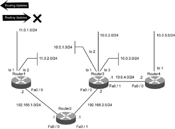
Figure 6.2: Passive interface configuration in Router1.
To verify if Router1 has been configured with a passive interface, we will look into its configuration using the command show running-config, shown in Listing 6.21.
Listing 6.21 Configuration of Router1 Using the show running-config Command
Router1#show running-config router rip network 192.168.1.0 network 11.0.0.0 passive-interface FastEthernet0/0
From the configuration of Router1, it is clear that the interface FastEthernet0/0 of Router1 has been configured as passive (as per the command passive-interface FastEthernet0/0). Therefore, this interface of Router1 configured as passive now will only be able to track the RIP routing updates and hold all its outgoing RIP routing updates via the configured interface, as depicted in Listing 6.21. When the interface is removed from the passive interface mode, it will immediately start sending its routing table to neighboring routers and will reach Router4. Router4 will modify its routing table as per the received updates and will be able to reach any host in networks 11.0.1.0 and 11.0.2.0. To remove an interface from passive mode, use the command no passive-interface fa0/0, as shown in Listing 6.22.
Listing 6.22 Removing an Interface Using the no passive-interface fa0/0 Command for Router4
Router1#conf t Router1(config)#router rip Router1(config-router)#no passive-interface fa0/0
RIP Is Not Installing All Possible Equal-Cost Paths
The RIP routing protocol supports equal-cost path load balancing; that is, when multiple equal cost paths exist, a router will use them to transmit data. Equal cost path refers to multiple routes to a common destination with the same metric values. By default, RIP can use up to four equal cost paths and can be configured to use a maximum of six equal cost paths. If the command is not configured accurately, it can lead to missing equal cost routes in the routing table. Figure 6.3 displays the redundant link between Router1 and Router4.
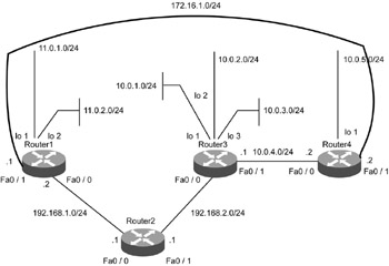
Figure 6.3: Redundant link between Router1 and Router4.
Consider a scenario in which there is a redundant link between Router1 and Router4 as shown in Figure 6.3. To access networks 10.0.1.0, 10.0.2.0 and 10.0.3.0 from Router1, there are two options:
-
Router1 to Router4 and finally to Router3
-
Router1 to Router2 and finally to Router3
A detailed understanding of both possible paths reveals the common path cost. Therefore, both these paths should exist in the routing table of Router1.
The routing table of Router1 shows only one path for destination networks 10.0.1.0, 10.0.2.0, and 10.0.3.0, as shown in Listing 6.23.
Listing 6.23 Routing Table of Router1
Router1#sh ip route Codes: C - connected, S - static, I - IGRP, R - RIP, M - mobile, B - BGP D - EIGRP, EX - EIGRP external, O - OSPF, IA - OSPF inter area E1 - OSPF external type 1, E2 - OSPF external type 2, E - EGP i - IS-IS, L1 - IS-IS level-1, L2 - IS-IS level-2, * - candidate default U - per-user static route Gateway of last resort is not set C 11.0.1.0/24 is directly connected, Loopback1 C 192.168.1.0/24 is directly connected, FastEthernet0/0 C 11.0.2.0/24 is directly connected, Loopback2 R 192.168.2.0/24 [120/1] via 192.168.1.1, 00:06:29, FastEthernet0/0 R 10.0.1.0/24 [120/2] via 192.168.1.1, 00:08:29, FastEthernet0/0 R 10.0.2.0/24 [120/2] via 192.168.1.1, 00:03:36, FastEthernet0/0 R 10.0.3.0/24 [120/2] via 192.168.1.1, 00:02:15, FastEthernet0/0 R 10.0.4.0/24 [120/2] via 192.168.1.1, 00:06:23, FastEthernet0/0 R 10.0.5.0/24 [120/3] via 192.168.1.1, 00:02:43, FastEthernet0/0
To identify the possible solution to the problem, it is important to understand the RIP updates that are being received by the Router1. To observe the routing updates, use the command debug ip rip. Listing 6.24 shows the routing updates in Router1.
Listing 6.24 Routing Updates in Router1
Router1#debug ip rip RIP: received v1 update from 172.16.1.2 on FastEthernet0/1 10.0.5.0 in 1 hops 10.0.4.0 in 1 hops 10.0.3.0 in 2 hops 10.0.2.0 in 2 hops 10.0.1.0 in 2 hops RIP: received v1 update from 192.168.1.1 on FastEthernet0/0 192.168.2.0 in 1 hops 10.0.3.0 in 2 hops 10.0.2.0 in 2 hops 10.0.1.0 in 2 hops RIP: sending v1 update to 255.255.255.255 via FastEthernet0/1(172.16.1.1) subnet 11.0.1.0, metric 1 subnet 11.0.2.3, metric 1 RIP: sending v1 update to 255.255.255.255 via FastEthernet0/0(192.168.1.2) subnet 11.0.1.0, metric 1 subnet 11.0.2.3, metric 1
From the debugging messages in Listing 6.24, it is evident that Router1 is receiving updates about the networks 10.0.1.0, 10.0.2.0, and 10.0.3.0 from two different sources but with the same metric value. Even after receiving updates from two sources, Router1 registers once, therefore, the origin of error is at Router1. To troubleshoot this, let us look into the configuration of Router1 using the command show run given in Listing 6.25.
Listing 6.25 Configuration of Router1 Using the Command show run
Router1#show run router rip network 192.168.1.0 network 11.0.0.0 maximum-path 1
By default, RIP-enabled routers can install four equal cost paths to a common destination, whereas in this scenario, the administrator has configured the router to install only one route to the destination. When only one path is desired for routing, the routers are configured using the command maximum-path 1. Therefore, the solution is to execute the command maximum-path 6 for the router to maintain a maximum of six equal cost paths for a destination. After this, Router1 will show two equal cost path routes each for networks 10.0.1.0, 10.0.2.0, and 10.0.3.0. This can be verified by looking at the routing table of Router1, as given in Listing 6.26.
Listing 6.26 Creation of Equal Cost Path Routes Using the Command maximum-path 6 for Router1
Router1#sh ip route Codes: C - connected, S - static, I - IGRP, R - RIP, M - mobile, B - BGP D - EIGRP, EX - EIGRP external, O - OSPF, IA - OSPF inter area E1 - OSPF external type 1, E2 - OSPF external type 2, E - EGP i - IS-IS, L1 - IS-IS level-1, L2 - IS-IS level-2, - candidate default U - per-user static route Gateway of last resort is not set C 11.0.1.0/24 is directly connected, Loopback1 C 192.168.1.0/24 is directly connected, FastEthernet0/0 C 11.0.2.0/24 is directly connected, Loopback2 R 192.168.2.0/24 [120/1] via 192.168.1.1, 00:06:29, FastEthernet0/0 R 10.0.1.0/24 [120/2] via 192.168.1.1, 00:08:29, FastEthernet0/0 [120/2] via 172.16.1.2, 00:08:29, FastEthernet0/1 R 10.0.2.0/24 [120/2] via 192.168.1.1, 00:03:36, FastEthernet0/0 [120/2] via 172.16.1.2, 00:03:36, FastEthernet0/1 R 10.0.3.0/24 [120/2] via 192.168.1.1, 00:02:15, FastEthernet0/0 [120/2] via 172.16.1.2, 00:02:15, FastEthernet0/1 R 10.0.4.0/24 [120/2] via 192.168.1.1, 00:06:23, FastEthernet0/0 R 10.0.5.0/24 [120/3] via 192.168.1.1, 00:02:43, FastEthernet0/0
EAN: 2147483647
Pages: 130