Preparing to Render Your Character s Skin
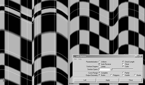
Preparing to Render Your Character's SkinBecause the focus of this book is modeling and character setup, creating materials and textures for your character's skin is covered only as it relates to the modeling process. This section shows you how to prepare for texturing your NURBS or polygon skins in Maya. NURBS Skin-Texturing ConsiderationsA NURBS skin is a true UV surface; so if you assign a normal 2D file texture to the surface, it wraps on the surface automatically. This can be an advantage over assigning a projected file texture, which will not work well on a complex surface that curves away from the projected angle. When texturing NURBS surfaces with a UV texture, however, keep in mind that the parameterization makes a difference in how the texture wraps on the surface. Uniform parameterization can be useful during the modeling process, and your surfaces can be left that way if you are going to convert them to a merged polygon skin, because then the texturing will be done at the polygon level. If you are planning to bind and animate your NURBS skin, however, you need to convert the parameterization of your surfaces before texturing. Using a Uniform parameterization on a complex surface that has variations in the spacing of the isoparms will cause unwanted stretching and compressing of the texture. The reason for this is that Uniform assigns the same amount of the texture image to each space between isoparms, no matter how small or large it is. So areas where the isoparms are close together cause the texture to compress, and areas where isoparms are far apart cause the texture to stretch. You can reduce this considerably by relofting all your NURBS patches to the Chord Length parameterization (see Figure 2.69). 2.69. When texturing NURBS surfaces, Uniform parameterization can cause distortion of the texture, whereas relofting the surfaces as Chord Length will produce a more even texture.
You can see the effect of parameterization in the Attribute Editor under the shape node. A Uniform parameterization has whole number values in the Min Max Range of the U and V fields. Usually the max range corresponds to the span's UV values. This causes the stretching and compressing, because each span is being allotted a value of 1, no matter how large it is on the surface. Then take the same surface and copy out the surface curves to reloft it with a new parameterization. In the Lofting options box, choose Chord Length parameterization, leaving all the other options the same. Make sure you repeat the process to convert both directions on the surface to Chord Length. If you then check the Attribute Editor, you should see decimal values in both the Max Range fields. The Chord Length parameterization assigns each span just the amount of texture it needs based on its size, and should make the texture wrap on the skin more evenly. Finally, if the texture is still not wrapping properly, open an Attribute Editor for each patch and turn on the Fix Texture Warp option in the Texture Map section. Set the grid division values based on the number of spans on your surfaces. For a multipatch character with many surfaces to set, you can also do this in the Attribute Spread Sheet under the Render tab. Another thing to be aware of when preparing to render a NURBS multipatch skin is that the resolution needs to be set higher to make the skin look continuous when rendered. Even if the patches appear to have perfect tangency in the hardware views, in your renders you may notice that small gaps appear at the seams between patches (see Figure 2.70). To fix this problem, drag a selection box around all the NURBS patches and choose Window, General Editors, Attribute Spread Sheet. In the Tessellation tab, you can click the name at the top of each column to type in a new tessellation setting for all the surfaces selected. Turn Explicit Tessellation Attributes to on, set the U and V Divisions Factor to 4.5, set the Curvature Tolerance to High Quality, and set the Smooth Edge to on with a Ratio of .99. Leave all the rest of the columns on their defaults, and try rendering your NURBS multipatch skin again. The skin should appear continuous, with no gaps at the seams between surfaces. If any gaps still appear, recheck the surfaces to make sure there isn't a tangency problem. You can continue to increase the U and V Divisions Factor values in the attribute spreadsheet, but this will increase your rendering time and should not be necessary on a skin that has been stitched well. 2.70. If small gaps appear at the seams of your multipatch skin when rendered, even though they appeared tangent in the hardware views, increase the tessellation settings for the surfaces in the Attribute Spread Sheet.
The best way to approach assigning a UV file texture to a NURBS skin is to assign numbered grids to each patch. You will then be able to see how all the NURBS patches are oriented, and adjust them if necessary. Then you can use the Maya 3D Paint tool to paint details on the grid surfaces. When this is done, you can then bring all the images into a paint program, such as Photoshop, and composite details on top of the painted images. To do this on your character's face, for instance, first create a basic 500x500-pixel grid in a paint program, complete with orientation and UV direction text markers, and save it as a TIF image. In Maya, open a hypershade view and create a new Phong material, naming it SkinGrid. Assign your grid to the Color attribute of a file texture by loading your image into the Image Name field. Then drag a selection box around your character's head patches to select them all and right-click the shader to choose Assign to Selected. Press the 6 key with your cursor in the perspective view to display the grids on your surfaces (see Figure 2.71). If any of the grids do not match up, or appear to be backward, this may be a sign that the surface should be reversed. Then drag a selection box around all the surfaces with a grid to paint on them. To activate the 3D Paint tool, in the Render module choose Texturing, 3D Paint Tool 2.71. You can assign a grid file texture to your skins to use as a surface guide when painting textures.
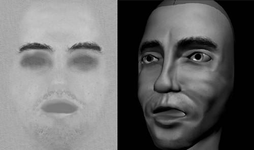
Painting on your NURBS patches will enable you to create a color map for your character's skin. A color map should have all the main color and textural variations that a real surface contains. Try not to make the color map too even and perfect. On a face, for instance, add imperfections and changes in tone. Increase the pore size in areas such as the cheeks and nose, darken areas in the eye sockets where the skin is thin, and add wrinkles on the forehead and cheeks. If your character shaves, add razor stubble on the chin. You must open each patch's file texture in Photoshop to composite skin, eyebrow, and lip textures onto the final color maps. You can create variations on the skin base by adding noise and cloud effects. Although assigning a normal UV file texture is preferable on a NURBS surface, it is time-consuming to create on a multipatch character. If you don't have the time to go through this process, you will want to project an image onto many NURBS surfaces instead. Make a face file texture of your character by taking a wireframe or shaded screenshot in the front view. In your paint program, paint and composite on top of the screenshot to create a texture to project from the front view onto all of your face patches. Then create another Phong material that you load your front face file texture into the Color attribute. In the resulting options box, where you can choose the projection type, choose Planar. Although you can assign one large texture map placed on as a cylindrical projection to your character's head, you also can separate your head textures into planes projected from several angles onto separate skin surface groups. Group all the patches you want to place the texture on, such as all the face patches, and right-click the front face shader to assign it to the group. Go to the material's Attribute Editor again, and in the Projection tab, click the Interactive Placement button to activate a texture projection manipulator. You should see a manipulator in your 3D views, and also see a place3Dtexture node in the hypergraph view. Click the Fit to Group Box button to place the manipulator around the assigned patches, and then manipulate its channels to position it so that it best fits the face. Because you created it from a screen capture, the finished projected texture should fit your character's face (see Figure 2.72). 2.72. A basic planar projected color map should look like the face, and will be easier to create in a paint program than painted textures on a multipatch head.
Projected textures are not locked to the UV surface, but are projected from specific angles like a slide image onto a screen. If you fold the screen, the image doesn't fold with it. A true UV texture behaves like it is painted on the surface, so it deforms with the surface. Creating a texture reference object for a projected texture will simulate this effect and lock the projected image to the surface. Create a texture reference object by selecting the group of face patches you assigned the projected texture, and in the Rendering module, choose Texturing, Create Texture Reference Object. You will see another set of pink skins in the 3D views, as well as a new reference group in the hypergraph view. You can move this group wherever is convenient, or just hide it. Then if you deform the textured skin patches, the file texture will deform with the skin appropriately. Regardless of whether you paint or project your maps, you can create other maps for your skins from the finished color map. The other maps commonly created for a character include bump, specular, and diffuse maps. These maps are normally grayscale modified versions of the color map and are assigned to the appropriate attributes in the material. The bump map produces a 2D bumpiness by creating highlights and shadows from the map values. The specular map controls the placement of specular highlights on specific areas to simulate shininess on the skin, whereas the diffuse map softens features in particular areas. You also will sometimes create transparency maps, which are grayscale maps that control the visibility of parts of the skin. When rendering a radial head with eye patches, for instance, it is common to use a ramp to create a soft transparent edge on the eye patches. This better hides the seams between surfaces. If you do this, however, make sure you set the eye patch rendering properties to not cast shadows; otherwise, the transparent edge will cast a shadow on the head and make the seam noticeable again. Polygon Skin-Texturing ConsiderationsUnlike NURBS surfaces, polygon objects must have their UV directions assigned to them. The UVs are created on the faces according to the method you choose in the Edit Polygons, Texture menu. To see the UVs of a particular polygon body part, you must open a floating UV texture view by choosing Window, UV Texture Editor. Try the different projection methods on your character's body parts to see which produces the best results. The important thing to avoid is having overlapping UVs, or having too many small pieces. The cylindrical projection is going to work well for many body parts, including the head, but stretching may occur in areas such as the neck. The Automatic mapping method will produce a result that has no overlapping UVs, but may create too many small pieces that have to be manually moved and sewed together (see Figure 2.73). You may get overlapping UVs using many of the other mapping methods, which will require relaxing the UVs in these areas to spread them out, and even some point by point tweaking. One thing to make the process easier is to cut your surfaces up before you map them to reduce the number of overlapping UVs. For instance, separate the face of your character from the rest of its head to map just the face with a planar or automatic projection. Then put them back together again after they are mapped. Some people even go through a process of flattening the geometry out to map it, and then deform it back into its original shape using a blend shape. Regardless of how you create your character's polygon UV map, when it is done, take a UV Snapshot of it in the Polygons menu to use as a guide when creating the color map in your paint program. Then assign the map as a file texture on your skin material and assign it back to the polygon skin. 2.73. Creating polygon UVs with the Automatic mapping method keeps the UVs from overlapping, but produces many small pieces that must be moved, sewed, and relaxed to create a good map.
|
EAN: 2147483647
Pages: 75