Lesson 1: Network Cabling
Building on our understanding of the different network topologies that connect computers, we focus next on the cables that connect them. In this lesson, we examine the construction, features, and operation of each type of cable, and the advantages and disadvantages of each.
After this lesson, you will be able to:
- Determine which type of cabling is best for any networking situation.
- Define terms related to cabling, such as shielding, crosstalk, attenuation, and plenum.
- Identify the primary types of network cabling.
- Distinguish between baseband and broadband transmissions and identify appropriate uses for each.
Estimated lesson time: 50 minutes
Primary Cable Types
The vast majority of networks today are connected by some sort of wiring or cabling that acts as a network transmission medium that carries signals between computers. Many cable types are available to meet the varying needs and sizes of networks, from small to large.
Cable types can be confusing. Belden, a leading cable manufacturer, publishes a catalog that lists more than 2200 types of cabling. Fortunately, only three major groups of cabling connect the majority of networks:
- Coaxial cable
- Twisted-pair (unshielded and shielded) cable
- Fiber-optic cable
The next part of this lesson describes the features and components of these three major cable types. Understanding their differences will help you determine which type of cabling is appropriate in a given context.
Coaxial Cable
At one time, coaxial cable was the most widely used network cabling. There were a couple of reasons for coaxial cable's wide usage: it was relatively inexpensive, and it was light, flexible, and easy to work with.
In its simplest form, coaxial cable consists of a core of copper wire surrounded by insulation, a braided metal shielding, and an outer cover. Figure 2.1 shows the various components that make up a coaxial cable.
The term shielding refers to the woven or stranded metal mesh (or other material) that surrounds some types of cabling. Shielding protects transmitted data by absorbing stray electronic signals, called noise, so that they do not get onto the cable and distort the data. Cable that contains one layer of foil insulation and one layer of braided metal shielding is referred to as dual shielded. For environments that are subject to higher interference, quad shielding is available. Quad shielding consists of two layers of foil insulation and two layers of braided metal shielding.
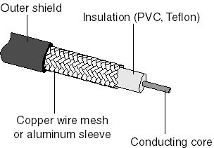
Figure 2.1 Coaxial cable showing various layers
The core of a coaxial cable carries the electronic signals that make up the data. This wire core can be either solid or stranded. If the core is solid, it is usually copper.
Surrounding the core is a dielectric insulating layer that separates it from the wire mesh. The braided wire mesh acts as a ground and protects the core from electrical noise and crosstalk. (Crosstalk is signal overflow from an adjacent wire. For a more detailed discussion of crosstalk, see the section Unshielded Twisted-Pair (UTP) Cable, later in this lesson.)
The conducting core and the wire mesh must always be kept separate from each other. If they touch, the cable will experience a short, and noise or stray signals on the mesh will flow onto the copper wire. An electrical short occurs when any two conducting wires or a conducting wire and a ground come into contact with each other. This contact causes a direct flow of current (or data) in an unintended path. In the case of household electrical wiring, a short will cause sparking and the blowing of a fuse or circuit breaker. With electronic devices that use low voltages, the result is not as dramatic and is often undetectable. These low-voltage shorts generally cause the failure of a device; and the short, in turn, destroys the data.
A nonconducting outer shield—usually made of rubber, Teflon, or plastic—surrounds the entire cable.
Coaxial cable is more resistant to interference and attenuation than twisted-pair cabling. As shown in Figure 2.2, attenuation is the loss of signal strength that begins to occur as the signal travels farther along a copper cable.

Figure 2.2 Attenuation causes signals to deteriorate
The stranded, protective sleeve absorbs stray electronic signals so that they do not affect data being sent over the inner copper cable. For this reason, coaxial cabling is a good choice for longer distances and for reliably supporting higher data rates with less sophisticated equipment.
Types of Coaxial Cable
There are two types of coaxial cable:
- Thin (thinnet) cable
- Thick (thicknet) cable
Which type of coaxial cable you select depends on the needs of your particular network.
Thinnet Cable Thinnet cable is a flexible coaxial cable about 0.64 centimeters (0.25 inches) thick. Because this type of coaxial cable is flexible and easy to work with, it can be used in almost any type of network installation. Figure 2.3 shows thinnet cable connected directly to a computer's network interface card (NIC).
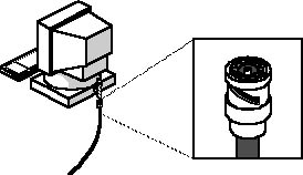
Figure 2.3 Close-up view of thinnet cable showing where it connects to a computer
Thinnet coaxial cable can carry a signal for a distance of up to approximately 185 meters (about 607 feet) before the signal starts to suffer from attenuation.
Cable manufacturers have agreed upon specific designations for different types of cable. (Table 2.1 lists cable types and descriptions.) Thinnet is included in a group referred to as the RG-58 family and has 50ohm impedance. (Impedance is the resistance, measured in ohms, to the alternating current that flows in a wire.) The principal distinguishing feature of the RG-58 family is the center core of copper. Figure 2.4 shows two examples of RG-58 cable, one with a stranded wire core and one with a solid copper core.
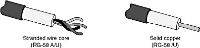
Figure 2.4 RG-58 coaxial cable showing stranded wire and solid copper cores
Table 2.1 Cable Types
| Cable | Description |
|---|---|
| RG-58/U | Solid copper core |
| RG-58 A/U | Stranded wire core |
| RG-58 C/U | Military specification of RG-58 A/U |
| RG-59 | Broadband transmission, such as cable television |
| RG-6 | Larger in diameter and rated for higher frequencies than RG-59, but also used for broadband transmissions |
| RG-62 | ArcNet networks |
Thicknet Cable Thicknet cable is a relatively rigid coaxial cable about 1.27 centimeters (0.5 inches) in diameter. Figure 2.5 shows the difference between thinnet and thicknet cable. Thicknet cable is sometimes referred to as Standard Ethernet because it was the first type of cable used with the popular network architecture Ethernet. Thicknet cable's copper core is thicker than a thinnet cable core.
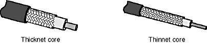
Figure 2.5 Thicknet cable has a thicker core than thinnet cable
The thicker the copper core, the farther the cable can carry signals. This means that thicknet can carry signals farther than thinnet cable. Thicknet cable can carry a signal for 500 meters (about 1640 feet). Therefore, because of thicknet's ability to support data transfer over longer distances, it is sometimes used as a backbone to connect several smaller thinnet-based networks.
Figure 2.6 shows a device called a transceiver. A transceiver connects the thinnet coaxial cable to the larger thicknet coaxial cable. A transceiver designed for thicknet Ethernet includes a connector known as a vampire tap, or a piercing tap, to make the actual physical connection to the thicknet core. This connector is pierced through the insulating layer and makes direct contact with the conducting core. Connection from the transceiver to the NIC is made using a transceiver cable (drop cable) to connect to the attachment unit interface (AUI) port connector on the card. An AUI port connector for thicknet is also known as a Digital Intel Xerox (DIX) connector (named for the three companies that developed it and its related standards) or as a DB-15 connector.
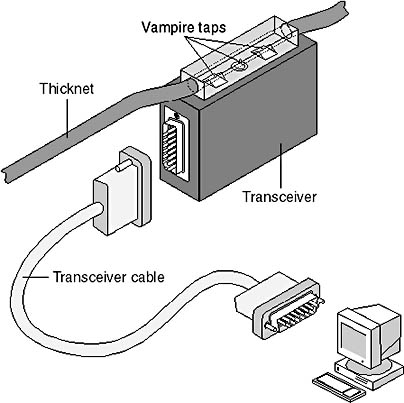
Figure 2.6 Thicknet cable transceiver with detail of a vampire tap piercing the core
Thinnet vs. Thicknet Cable As a general rule, the thicker the cable, the more difficult it is to work with. Thin cable is flexible, easy to install, and relatively inexpensive. Thick cable does not bend easily and is, therefore, harder to install. This is a consideration when an installation calls for pulling cable through tight spaces such as conduits and troughs. Thick cable is more expensive than thin cable, but will carry a signal farther.
Coaxial-Cable Connection Hardware
Both thinnet and thicknet cable use a connection component, known as a BNC connector, to make the connections between the cable and the computers. There are several important components in the BNC family, including the following:
- The BNC cable connector Figure 2.7 shows a BNC cable connector. The BNC cable connector is either soldered or crimped to the end of a cable.
- The BNC T connector Figure 2.8 shows a BNC T connector. This connector joins the network interface card (NIC) in the computer to the network cable.
- The BNC barrel connector Figure 2.9 shows a BNC barrel connector. This connector is used to join two lengths of thinnet cable to make one longer length.
- The BNC terminator Figure 2.10 shows a BNC terminator. A BNC terminator closes each end of the bus cable to absorb stray signals. Otherwise, as we saw in Chapter 1, "Introduction to Networking," the signal will bounce and all network activity will stop.
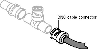
Figure 2.7 BNC cable connector

Figure 2.8 BNC T connector
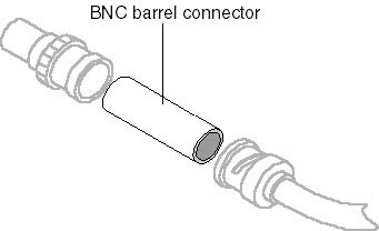
Figure 2.9 BNC barrel connector

Figure 2.10 BNC terminator
NOTE
The origin of the acronym "BNC" is unclear, and there have been many names ascribed to these letters, from "British Naval Connector" to "Bayonet Neill-Councelman." Because there is no consensus on the proper name and because the technology industry universally refers to these simply as BNC-type connectors, in this book we will refer to this family of hardware simply as BNC.
Coaxial-Cable Grades and Fire Codes
The type of cable grade that you should use depends on where the cables will be laid in your office. Coaxial cables come in two grades:
- Polyvinyl chloride (PVC) grade
- Plenum grade
Polyvinyl chloride (PVC) is a type of plastic used to construct the insulation and cable jacket for most types of coaxial cable. PVC coaxial cable is flexible and can be easily routed through the exposed areas of an office. However, when it burns, it gives off poisonous gases.
A plenum is the shallow space in many buildings between the false ceiling and the floor above; it is used to circulate warm and cold air through the building. Figure 2.11 shows a typical office and where to use—or not use—PVC and plenum-grade cables. Fire codes give very specific instructions about the type of wiring that can be routed through this area, because any smoke or gas in the plenum will eventually blend with the air breathed by everyone in the building.
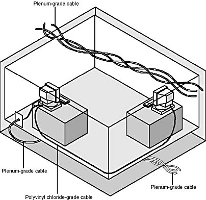
Figure 2.11 Plenum-grade cabling is required in the plenum by fire codes
Plenum-grade cabling contains special materials in its insulation and cable jacket. These materials are certified to be fire resistant and produce a minimum amount of smoke; this reduces poisonous chemical fumes. Plenum cable can be used in the plenum area and in vertical runs (for example, in a wall) without conduit. However, plenum cabling is more expensive and less flexible than PVC cable.
NOTE
You should consult your local fire and electrical codes for specific regulations and requirements for running networking cable in your office.
Coaxial-Cabling Considerations
Consider the following coaxial capabilities when making a decision about which type of cabling to use.
Use coaxial cable if you need a medium that can:
- Transmit voice, video, and data.
- Transmit data for greater distances than is possible with less expensive cabling.
- Offer a familiar technology with reasonable data security.
Twisted-Pair Cable
In its simplest form, twisted-pair cable consists of two insulated strands of copper wire twisted around each other. Figure 2.12 shows the two types of twisted-pair cable: unshielded twisted-pair (UTP) and shielded twisted-pair (STP) cable.
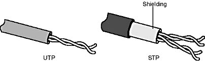
Figure 2.12 Unshielded twisted-pair and shielded twisted-pair cables
A number of twisted-pair wires are often grouped together and enclosed in a protective sheath to form a cable. The total number of pairs in a cable varies. The twisting cancels out electrical noise from adjacent pairs and from other sources such as motors, relays, and transformers.
Unshielded Twisted-Pair (UTP) Cable
UTP, using the 10BaseT specification, is the most popular type of twisted-pair cable and is fast becoming the most popular LAN cabling. The maximum cable length segment is 100 meters, about 328 feet.
Traditional UTP cable, as shown in Figure 2.13, consists of two insulated copper wires. UTP specifications govern how many twists are permitted per foot of cable; the number of twists allowed depends on the purpose to which the cable will be put. In North America, UTP cable is the most commonly used cable for existing telephone systems and is already installed in many office buildings.

Figure 2.13 UTP cable
The 568A Commercial Building Wiring Standard of the Electronic Industries Association and the Telecommunications Industries Association (EIA/TIA) specifies the type of UTP cable that is to be used in a variety of building and wiring situations. The objective is to ensure consistency of products for customers. These standards include five categories of UTP:
- Category 1 This refers to traditional UTP telephone cable that can carry voice but not data transmissions. Most telephone cable prior to 1983 was Category 1 cable.
- Category 2 This category certifies UTP cable for data transmissions up to 4 megabits per second (Mbps). It consists of four twisted pairs of copper wire.
- Category 3 This category certifies UTP cable for data transmissions up to 16 Mbps. It consists of four twisted pairs of copper wire with three twists per foot.
- Category 4 This category certifies UTP cable for data transmissions up to 20 Mbps. It consists of four twisted pairs of copper wire.
- Category 5 This category certifies UTP cable for data transmissions up to 100 Mbps. It consists of four twisted pairs of copper wire.
Most telephone systems use a type of UTP. In fact, one reason why UTP is so popular is because many buildings are prewired for twisted-pair telephone systems. As part of the prewiring process, extra UTP is often installed to meet future cabling needs. If preinstalled twisted-pair cable is of sufficient grade to support data transmission, it can be used in a computer network. Caution is required, however, because common telephone wire might not have the twisting and other electrical characteristics required for clean, secure, computer data transmission.
One potential problem with all types of cabling is crosstalk. Figure 2.14 shows crosstalk between two UTP cables. (As discussed earlier in this lesson, crosstalk is defined as signals from one line interfering with signals from another line.) UTP is particularly susceptible to crosstalk, but the greater the number of twists per foot of cable, the more effective the protection against crosstalk.

Figure 2.14 Crosstalk occurs when signals from one line bleed into another line
Shielded Twisted-Pair (STP) Cable
STP cable uses a woven copper-braid jacket that is more protective and of a higher quality than the jacket used by UTP. Figure 2.15 shows a two-twisted-pair STP cable. STP also uses a foil wrap around each of the wire pairs. This gives STP excellent shielding to protect the transmitted data from outside interference, which in turn allows it to support higher transmission rates over longer distances than UTP.

Figure 2.15 STP cable
Twisted-Pair Cabling Components
While we have defined twisted-pair cabling by the number of twists and its ability to transmit data, additional components are necessary to complete an installation. As it is with telephone cabling, a twisted-pair cable network requires connectors and other hardware to ensure proper installation.
Connection hardware Twisted-pair cabling uses RJ-45 telephone connectors to connect to a computer. These are similar to RJ-11 telephone connectors. An RJ-45 connector is shown in Figure 2.16. Although RJ-11 and RJ-45 connectors look alike at first glance, there are crucial differences between them.
The RJ-45 connector is slightly larger and will not fit into the RJ-11 telephone jack. The RJ-45 connector houses eight cable connections, while the RJ-11 houses only four.
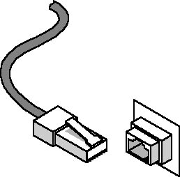
Figure 2.16 RJ-45 connector and jack
Several components are available to help organize large UTP installations and make them easier to work with. Figure 2.17 shows various twisted-pair cabling components.
Distribution racks and rack shelves Distribution racks and rack shelves can create more room for cables where there isn't much floor space. Using them is a good way to organize a network that has a lot of connections.
Expandable patch panels These come in various versions that support up to 96 ports and transmission speeds of up to 100 Mbps.
Jack couplers These single or double RJ-45 jacks snap into patch panels and wall plates and support data rates of up to 100 Mbps.
Wall plates These support two or more couplers.
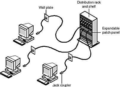
Figure 2.17 Various twisted-pair cabling components
Twisted-Pair Cabling Considerations
Use twisted-pair cable if:
- Your LAN is under budget constraints.
- You want a relatively easy installation in which computer connections are simple.
Do not use twisted-pair cable if:
- Your LAN requires a high level of security and you must be absolutely sure of data integrity.
- You must transmit data over long distances at high speeds.
Fiber-Optic Cable
In fiber-optic cable, optical fibers carry digital data signals in the form of modulated pulses of light. This is a relatively safe way to send data because, unlike copper-based cables that carry data in the form of electronic signals, no electrical impulses are carried over the fiber-optic cable. This means that fiberoptic cable cannot be tapped, and its data cannot be stolen.
Fiber-optic cable is good for very high-speed, high-capacity data transmission because of the purity of the signal and lack of signal attenuation.
Fiber-Optic Cable Composition
An optical fiber consists of an extremely thin cylinder of glass, called the core, surrounded by a concentric layer of glass, known as the cladding. The fibers are sometimes made of plastic. Plastic is easier to install, but cannot carry the light pulses for as long a distance as glass.
Because each glass strand passes signals in only one direction, a cable includes two strands in separate jackets. One strand transmits and one receives. A reinforcing layer of plastic surrounds each glass strand, and Kevlar fibers provide strength. See Figure 2.18 for an illustration of fiber-optic cable. The Kevlar fibers in the fiber-optic connector are placed between the two cables. Just as their counterparts (twisted-pair and coaxial) are, fiber-optic cables are encased in a plastic coating for protection.
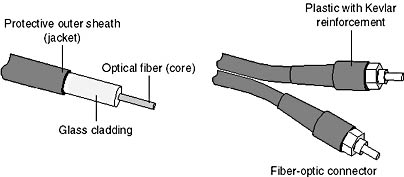
Figure 2.18 Fiber-optic cable
Fiber-optic cable transmissions are not subject to electrical interference and are extremely fast, currently transmitting about 100 Mbps with demonstrated rates of up to 1 gigabit per second (Gbps). They can carry a signal—the light pulse—for many miles.
Fiber-Optic Cabling Considerations
Use fiber-optic cable if you:
- Need to transmit data at very high speeds over long distances in very secure media.
Do not use fiber-optic cable if you:
- Are under a tight budget.
- Do not have the expertise available to properly install it and connect devices to it.
NOTE
Pricing for fiber-optic cable is competitive with high-end copper cabling. Fiber-optic cable has become increasingly easier to work with, and polishing and terminating techniques now require fewer parts and less expertise than just a few years ago.
Signal Transmission
Two techniques can be used to transmit the encoded signals over cable: baseband and broadband transmission.
Baseband Transmission
Baseband systems use digital signaling over a single channel. Signals flow in the form of discrete pulses of electricity or light. Figure 2.19 shows a baseband transmission with a bidirectional digital wave. With baseband transmission, the entire communication channel capacity is used to transmit a single data signal. The digital signal uses the complete bandwidth of the cable, which constitutes a single channel. The term bandwidth refers to the data transfer capacity, or speed of transmission, of a digital communications system as measured in bits per second (bps).
![]()
Figure 2.19 Baseband transmission showing digital wave
As the signal travels along the network cable, it gradually decreases in strength and can become distorted. If the cable length is too long, the received signal can be unrecognizable or misinterpreted.
As a safeguard, baseband systems sometimes use repeaters to receive incoming signals and retransmit them at their original strength and definition. This increases the practical length of a cable.
Broadband Transmission
Broadband systems, as shown in Figure 2.20, use analog signaling and a range of frequencies. With analog transmission, the signals are continuous and nondiscrete. Signals flow across the physical medium in the form of electromagnetic or optical waves. With broadband transmission, signal flow is unidirectional.

Figure 2.20 Broadband transmission showing unidirectional analog wave
If sufficient total bandwidth is available, multiple analog transmission systems, such as cable television and network transmissions, can be supported simultaneously on the same cable.
Each transmission system is allocated a part of the total bandwidth. All devices associated with a given transmission system, such as all computers using a LAN cable, must then be tuned so that they use only the frequencies that are within the allocated range.
While baseband systems use repeaters, broadband systems use amplifiers to regenerate analog signals at their original strength.
In broadband transmission, signals flow in one direction only, so there must be two paths for data flow in order for a signal to reach all devices. There are two common ways to do this:
- Through mid-split broadband configuration, the bandwidth is divided into two channels, each using a different frequency or range of frequencies. One channel transmits signals; the other receives signals.
- In dual-cable broadband configuration, each device is attached to two cables. One cable is used to send, and the other is used to receive.
Increasing Bandwidth Performance
Increasing the speed of data transmission is a priority as network sizes and data traffic increase. By maximizing the use of the data channel, we can exchange more data in less time. The most basic form of data or information transmission is called simplex. This means that data is sent in one direction only, from sender to receiver. A simplex transmission is shown in Figure 2.21. Examples of simplex transmission are radio and television. With simplex transmission, problems encountered during the transmission are not detected and corrected. Senders cannot even be sure that the data is received.

Figure 2.21 A simplex transmission
In the next level of data transmission, called half-duplex transmission, data is sent in both directions, but in only one direction at a time. Examples of technology that uses half-duplex communication are shortwave radio and walkie-talkies. Figure 2.22 shows a half-duplex transmission. With half-duplex transmission, you can incorporate error detection and request that any bad data be resent. Surfing the World Wide Web is a form of half-duplex data transmission. You send a request for a Web page and then wait while it is being sent back to you. Most modem connections use half-duplex data transmission.

Figure 2.22 A half-duplex transmission
The most efficient method of transmitting data is to use a full-duplex transmission, in which data can be transmitted and received at the same time. A good example is a cable connection that not only allows you to receive TV channels, but also supports telephone and Internet connection. A telephone is a full-duplex device because it allows both parties to talk at the same time. Figure 2.23 shows full-duplex communication. Modems, by design, are half-duplex devices. They either send or receive data, switching between transmission mode and receiving mode. You can create a full-duplex modem channel by using two modems and two telephone lines. The only requirement is that both computers be connected and configured to support this type of communication.
Figure 2.23 Full-duplex communication
The IBM Cabling System
IBM has developed its own cabling system, complete with its own numbers, standards, specifications, and designations. Many of these parameters, however, are similar to non-IBM specifications.
IBM introduced its cabling system in 1984. The purpose of this system was to ensure that the cabling and connectors would meet the specifications of their equipment. The IBM specification includes the following components:
- Cable connectors
- Face plates
- Distribution panels
- Cable types
The one IBM cabling component that is unique is the IBM connector, which is different from standard BNC or other connectors. These are IBM Type A connectors, known elsewhere as universal data connectors. They are neither male nor female; you can connect one to another by flipping either one over. These IBM connectors require special faceplates and distribution panels to accommodate their unique shape.
The IBM cabling system classifies cable into types. For example, in the IBM system, Category 3 cable (voice-grade UTP cable) is referred to as Type 3. (Table 2.2 compares the IBM cabling-system type names with standard cable type names.) The cable definitions specify which cable is appropriate for a given application or environment. The wire indicated in the system conforms to American Wire Gauge (AWG) standards.
AWG: The Standard Cable Measurement
Cable measurements are often expressed as numbers, followed by the initials AWG. (AWG is a measurement system for wire that specifies its thickness.) As the thickness of the wire increases, the AWG number decreases. Telephone wire is often used as a reference point; it has a thickness of 22 AWG. A wire of 14 AWG is thicker than telephone wire, and wire of 26 AWG is thinner than telephone wire.
Table 2.2 IBM Cabling System
| IBM type | Standard label | Description |
|---|---|---|
| Type 1 | Shielded twisted-pair | Two pairs of 22 AWG wires surrounded (STP) cable by an outer braided shield; used for computers and multistation access units (MAUs) |
| Type 2 | Voice and data cable | A voice and data shielded cable with two twisted pairs of 22 AWG wires for data, an outer braided shield, and four twisted pairs of 26 AWG wires for voice |
| Type 3 | Voice-grade cable | Consists of four solid, unshielded twisted-pair, 22 or 24 AWG cables |
| Type 4 | Undefined | |
| Type 5 | Fiber-optic cable | Two 62.5/125-micron multimode optical fibers—the industry standard |
| Type 6 | Data patch cable | Two 26 AWG twisted-pair stranded cables with a dual foil and braided shield |
| Type 7 | Undefined | |
| Type 8 | Carpet cable | Housed in a flat jacket for use under carpets; two shielded twisted-pair 26 AWG cables; limited to one half the distance of Type 1 cable |
| Type 9 | Plenum-grade cable | Fire safe Two shielded twisted-pair cables |
NOTE
A Multistation Access Unit (MAU) is a hub device in a token-ring network that connects computers in a physical hub-and-spokes arrangement, but uses the logical ring required in token ring networks.
Selecting Cabling
To determine which cabling is the best for a particular site you need to answer the following questions:
- How heavy will the network traffic be?
- What level of security does the network require?
- What distances must the cable cover?
- What are the cable options?
- What is the budget for cabling?
The better the cable protects against internal and external electrical noise, the farther and faster the cable will carry a clear signal. However, the better the speed, clarity, and security of the cable, the higher the cabling cost.
Cabling Considerations
As with most network components, there are trade-offs with the type of cable you purchase. If you work for a large organization and choose the least expensive cable, the accountants might initially be pleased, but you might soon notice that the LAN is inadequate in both transmission speed and data security.
Which cabling you select will depend on the needs of a particular site. The cabling you purchase to set up a LAN for a small business has different requirements from those of a larger organization, such as a major banking institution.
In the rest of this section, we examine some of the considerations that affect cabling price and performance.
Table 2.3 provides comparative information on cabling types.
Installation Logistics
How easy is the cable to install and work with? In a small installation where distances are short and security isn't a major issue, it does not make sense to choose thick, cumbersome, and expensive cable.
Shielding
The level of shielding required will affect cable cost. Almost every network uses some form of shielded cable. The noisier the area in which the cable is run, the more shielding will be required. The same shielding in a plenum-grade cable will be more expensive as well.
Crosstalk
Crosstalk and noise can cause serious problems in large networks where data integrity is crucial. Inexpensive cabling has low resistance to outside electrical fields generated by power lines, motors, relays, and radio transmitters. This makes it susceptible to both noise and crosstalk.
Transmission Rates
Transmission rates are measured in megabits per second. A standard reference point for current LAN transmission over copper cable is 100 Mbps. Fiber-optic cable transmits at more than 1 Gbps.
Cost
Higher grades of cables can carry data securely over long distances, but they are relatively expensive; lower-grade cables, which provide less data security over shorter distances, are relatively inexpensive.
Signal Attenuation
Different cable types have different rates of attenuation; therefore, cable specifications recommend specific length limits for the different types. If a signal suffers too much attenuation, the receiving computer will be unable to interpret it. Most networks have error-checking systems that will generate a retransmission if the signal is too weak to be understood. However, retransmission takes time and slows down the network.
Table 2.3 Cable Comparison Summary
| Characteristics | Thinnet coaxial (10Base2) Cable | Thicknet coaxial (10Base5) Cable | Twisted-pair (10BaseT) Cable1 | Fiber-optic Cable |
|---|---|---|---|---|
| Cable cost | More than UTP | More than thinnet | UTP: Least expensive STP: More than thinnet | More than thinnet, but less than thicknet |
| Usable cable length2 | 185 meters (about 607 feet) | 500 meters (about 1640 feet) | UTP and STP: 100 meters (about 328 feet) | 2 kilometers (6562 feet) |
| Transmission rates | 4-100 Mbps | 4-100 Mbps | UTP: 4-100 Mbps STP: 16-500 Mbps | 100 Mbps or more ( > 1Gbps) |
| Flexibility | Fairly flexible | Less flexible than thinnet | UTP: Most flexible STP: Less flexible than UTP | Less flexible than thicknet |
| Ease of installation | Easy to install | Moderately easy to install | UTP: Very easy; often preinstalled STP: Moderately easy | Difficult to install |
| Susceptibility to interference | Good resistance to interference | Good resistance to interference | UTP: Very susceptible STP: Good resistance | Not susceptible to interference |
| Special features | Electronic support components are less expensive than twisted-pair cable | Electronic support components are less expensive than twisted-pair cable | UTP: Same as telephone wire; often preinstalled in buildings STP: Supports higher transmission rates than UTP | Supports voice, data, and video |
| Preferred uses | Medium to large sites with high security needs | Linking thinnet networks | UTP: smaller sites on budget. STP: Token Ring in any size | Any size installation requiring speed and high data security and integrity |
1 This column provides information for both unshielded twisted-pair (UTP) and twisted-pair (STP) cable.
2 Usable cable length can vary with specific network installations. As technology improves, usable cable length also increases.

Exercise 2.1: Case Study Problem
You have been asked to review the proposals submitted by a consulting firm to design the cabling scheme for your company's new office building. Table 2.4 and the following diagram illustrate your company's cabling needs.
Table 2.4 Your Company's Cabling Needs
| Location | Distance | Location | Distance |
|---|---|---|---|
| A to B | 15 meters (50 feet) | Hub to A | 152 meters (500 feet) |
| B to C | 15 meters (50 feet) | Hub to B | 160 meters (525 feet) |
| C to D | 15 meters (50 feet) | Hub to C | 168 meters (550 feet) |
| D to E | 61 meters (200 feet) | Hub to D | 184 meters (600 feet) |
| E to F | 23 meters (75 feet) | Hub to E | 152 meters (500 feet) |
| F to G | 23 meters (75 feet) | Hub to F | 130 meters (425 feet) |
| G to H | 23 meters (75 feet) | Hub to G | 107 meters (351feet) |
| H to I | 23 meters (75 feet) | Hub to H | 91 meters (300 feet) |
| I to J | 61 meters (200 feet) | Hub to I | 84 meters (275 feet) |
| J to K | 15 meters (50 feet) | Hub to J | 107 meters (351 feet) |
| K to L | 15 meters (50 feet) | Hub to K | 99 meters (325 feet) |
| L to M | 15 meters (50 feet) | Hub to L | 84 meters (275 feet) |
| A to M | 221 meters (725 feet) | Hub to M | 69 meters (226 feet) |
| D to M | 244 meters (800 feet) | A to J | 244 meters (800 feet) |
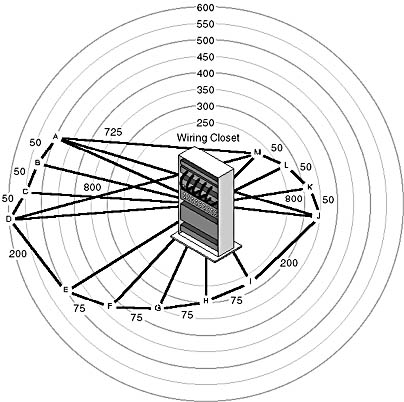
The consulting firm has recommended that you implement 10BaseT Category 5 UTP wire for your company's network. Based on this information, answer the following questions:
- Where does this recommendation violate the UTP and 10BaseT specifications?
- What type of cabling might you recommend instead?
Answers
Lesson Summary
The following points summarize the main elements of this lesson:
- Three primary types of cables are used with networks: coaxial, twisted-pair, and fiber-optic.
- Coaxial cable comes in two varieties: thinnet and thicknet.
- Thinnet cable is about 0.64 centimeters thick (0.25 inches) and can carry a signal for a distance of up to 185 meters (607 feet).
- Thicknet cable is about 1.27 centimeters (0.5 inches) in diameter and can carry a signal for a distance of up to 500 meters (1640 feet).
- The BNC connector is used with both thinnet and thicknet cables.
- Coaxial cables come in two grades, classified according to how they will be used: PVC-grade cable is used in exposed areas; plenum-grade cable has a fire-safety rating and is used in enclosed areas such as ceilings and walls.
- Twisted-pair cable can be either shielded (STP) or unshielded (UTP).
- The number of twists per unit of length and the protective shielding provide protection from interference.
- Twisted-pair cables conform to five standards, called categories. Each category provides specifications for increasing the speed of data transmission and resistance to interference.
- Twisted-pair cables use RJ-45 telephone connectors to connect to computers and hubs.
- Fiber-optic cables use light to carry digital signals.
- Fiber-optic cables provide the greatest protection from noise and intrusion.
- Data signals can be either baseband or broadband.
- Baseband transmission uses digital signals over a single frequency.
- Broadband transmission uses analog signals over a range of frequencies.
- IBM uses its own system of cabling and standards, but follows the same basic technology as other cables.
EAN: 2147483647
Pages: 106