Initial Project Planning
|
The project planning for this project is divided into two sections: project management planning and project implementation planning. This structure provides an easy-to-use reference for both managers and developers. Project management planning deals mainly with higher-level managerial planning, whereas project implementation planning is focused on implementation-related details that the developers should follow during the course of the project. |
4.4.1 Project Management Planning
Project management planning focuses on the procedures and tools imposed on the project to reduce risk, improve tracking, and improve quality. Even though commercial tools are available that provide process support for the whole life cycle, it was decided not to use these tools for the following reasons:
- None of the tools can be used without spending a considerable amount of time and effort in customizing it, setting it up, and training.
- For small teams, such as the three-person Online Photo Shop project, the tools would add unnecessary overhead.
- Not all of the automation the tools provide is needed for this project.
- The tools are expensive.
For completeness and for the interested reader, we'll mention that Rational provides a comprehensive tool collection that supports the Rational Unified Process (which is compatible with the Unified Process, as discussed in Chapter 2).
Software Configuration Management
Software configuration management (SCM) is a critical element for all development activities, not just coding. SCM facilitates change history and change control, and it enables parallel development. There are many strategies to SCM. In small projects with small teams, the strategy might be simply to compile the project, run the tests, zip the source files, and store them with a date and version indicator on a rewritable compact disc (CD/R).
A more advanced approach is to use tools such as Microsoft Visual Source Safe, WinCVS, or Rational ClearCase. All three tools provide advanced features for version control, including version history, branching, and merging. ClearCase also provides multisite support for distributed teams. In addition, you can find many other tools by searching the Internet for configuration management systems.
Recently a new approach to project code sharing over the Internet was introduced on the www.gotdotnet.com site. The Web site enables teams to share workspaces over the Internet by facilitating code sharing (for distributed teams even in different network domains), version control, and defect tracking.
The tool of choice for this project is Microsoft Visual Source Safe. It was chosen because of its rich set of features to support small team development in addition to its ease of setup and use. Visual Source Safe allows a developer to move files from the repository onto his or her local hard drive; this action is called checkout. When all the changes have been made (or a partial result has been achieved), the files are transferred back into the repository; this is called checkin. At checkin, new versions of the changed files are created, and all developers are able to see the changes. Configuration management enables you to roll back to previous versions if necessary, and it provides a change history that lets you backtrack changes. In addition, the configuration management systems enable parallel development and facilitate merging of the various changes. All versions are preserved and are easily accessible.
The only rule imposed on the developers is to provide meaningful summaries of the changes made as checkin comments. Good checkin comments enable the developers and management to find specific changes by browsing the version history without even looking at the differences in the source files.
Part of configuration management is to define a well-structured directory tree for the project source files and generated binaries. Figure 4.3 shows the directory structure of the Online Photo Shop as it is provided on the accompanying CD.
Figure 4.3. Directory Structure for the Online Photo Shop
The name of the top-level directory usually is the same as that of the project (in our case, that would be Online Photo Shop). However, for easy navigability and because we are providing sample solutions for each chapter, we chose to name the top-level directory for each chapter's solution Chapter X, where X represents the chapter number.
The next level contains the doc, bin, bind, and src directories. The doc directory holds all documentation that is automatically generated from the source code. The bin directory holds the generated assemblies that were compiled in release mode, and the bind directory holds the generated assemblies that were compiled in debug mode.
The src directory contains one Visual Studio solution, which will hold all the subprojects and source files. The projects reside in the subdirectories of src. These subdirectories contain modules that can be built independently of each other (such as SomePlugIn, Photo Editor Application, and so on). Nevertheless, as mentioned before, for easier access and compilation these modules or projects (in terms of Visual Studio) are part of one photo editor solution that contains all subprojects.
The Test directory contains the source for all the developed unit test cases, and the PhotoEditor directory contains subdirectories for each project module, which in turn contain all necessary source files to build the independent modules. Exception Management Application Block is an example of an external source that is provided by Microsoft and is therefore not a subproject of the photo editor.
It is a good practice for the configuration management system administrator to create and set up the directory tree structure for a new project.
Requirements Tracing
In every project it is important to track the requirements throughout the development phases to make sure that none of the keys has been forgotten. This sounds trivial, but in practice it is not unusual to discover missing implementations of certain requirements just before or even after a product is released. For this reason we strongly encourage you to track requirements with unique keys from their introduction through design, implementation, and test.
Earlier in this chapter we introduced the requirement keys for Online Photo Shop using an XML document that allows easy extraction of the keys for tracing. The requirement keys also are added to each class or method header in the code that implements or tests certain functionality. To do that, we use an XML requirement tag. Listing 4.3 shows an example in which the functional requirement key F:order_products is added to the header of the class WebForm1.
Listing 4.3 Example for Class Header Containing a Requirement Key
///
/// Summary description for WebForm1. ///
/// F:order_products public class WebForm1 : System.Web.UI.Page { ... }
In C# you can automatically generate documentation from the shown class headers using Visual Studio.NET (unfortunately, this feature is not yet available for VB). To automatically create the documentation from the source code, go to the project properties by right-clicking on the project in Solution Explorer and choosing Properties. The dialog shown in Figure 4.4 will open. Go to the Output section and type a file name (for example, PhotoEditorDocu.XML) into the XML Documentation File setting. After compiling the project, you will be able to find the XML documentation file in the output directory of the project.
Figure 4.4. Creating XML Documentation from Code
The same scheme of adding the requirement tag also applies to analysis and design documents. Furthermore, it will be used within the test outputs (log files), a practice that allows us to estimate test coverage. Information on document extraction from XML documents is explained in more detail in the next iteration of the project (Chapter 5).
Effort Estimates and Resource Allocation
Based on the requirements, the team must estimate the effort for each requirement. It is important to emphasize that effort estimates should be a team effort and not just a management effort. Effort estimates are based on experience, the expertise of the developers, and the environment.
In this project the estimates are made by at least two people. One is the person most likely to implement the requirement, and the other one is a senior developer who is familiar with the project and the environment. The estimates are based on the ideal development time, not considering any destruction, breaks, customer support, or similar contingencies. If there is a big discrepancy between the two estimates, a discussion is initiated to resolve the differences and reach a conclusion with a reasonable estimate. If the two estimates are within a reasonable range, then we add 25 percent fudge time plus some risk buffer. The risk buffer depends on the complexity of the task. The more complex the task or the more uncertainty it involves, the more risk buffer we add. It should be mentioned here that vacation time and training should be accounted for in the schedule as nonworking time.
The initial effort estimate for Online Photo Shop is visualized in Visio and is shown in Figure 4.5.
Figure 4.5. Initial Effort Estimate
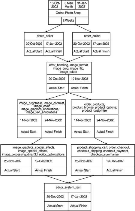
As shown in the overview, the requirements have been grouped by the development team. This grouping is based on related functionalities and is a first guess that will be refined in the iteration planning. Even though it is not shown here, it should be mentioned that each requirement is estimated individually.
In later iterations, defects that have been found must be estimated and scheduled in the same way as we've described for new requirements. In fact, the defects can be seen as new requirements, and they will be scheduled according to their priority.
Iteration Planning
Iteration planning is the task of combining one or more requirements into iterations. Usually, you bundle related functionality into the same iteration. In discussions with the customer and based on the initial effort estimates, you decide and agree upon the features that will be worked on during each iteration. This ensures that requirements that are important to the customer will be provided as early as possible. Also, to identify possible problem areas as early as possible, you put requirements that have more risk into the earlier construction iterations (in addition to a developed prototype in the inception phase). Single iterations should not exceed much more than two weeks' effort. This improves the accuracy of your progress tracking and helps you uncover problem areas faster. Iterations can be worked on in parallel if there are limited and well-defined dependencies.
For the Online Photo Shop application, Table 4.4 shows the iterations that have been identified.
|
Phase |
Iteration |
Type: Requirement Key |
|---|---|---|
|
Inception phase |
Iteration 1 Iteration 2 |
N/A N/A |
|
Elaboration phase |
Iteration 3 |
F:photo_editor C:imageprocessing_library C:platform_os F:error_handling F:image_format F:image_crop F:image_flip F:image_rotate |
|
Construction phase |
Iteration 4 |
F:image_brightness F:image_contrast F:image_color F:image_graphics_annotations F:image_text_annotations |
|
Iteration 5 |
F:image_graphics_special_effects |
|
|
Iteration 6 |
F:image_special_effects |
|
|
Iteration 7 |
F:image_accessing_system_resources |
|
|
Iteration 8 |
P:editor_optimizations |
|
|
Iteration 9 |
F:order_products F:product_browse F:product_options F:product_customize F:product_shopping_cart F:order_checkout F:checkout_shipping C:checkout_shipping_cont F:checkout_payment C:checkout_payment_method |
|
|
Iteration 10 |
R:checkout_payment_secure F:checkout_summarize C:online_shop_codebehind C:online_shop_stateservice |
|
|
Transition phase |
Iteration 11 |
F:editor_system_test |
Even though the iterations are described sequentially in this book, some of the iterations (with few functional dependencies) can be worked on in parallel. The sequential presentation is chosen because the team is small and the book is sequential by itself.
As you can see, the iteration planning has refined the initial effort estimates by grouping functionalities to accommodate the customer's priorities and wishes.
Project Tracking
Initial effort estimates and resource allocations are the base for progress tracking. Because the iterations should not exceed two weeks and because each iteration defines clear go/no-go criteria, we can identify problem areas very early and take countermeasures. Project tracking is the basic control that proves that the plan as shown in Figure 4.5 corresponds with reality. We must make continuous adjustments to the plan to keep it current and to track the reality.
It is a common problem that the plan made in the beginning is not adjusted during the course of the project. This leads to wishful plans that soon have nothing to do with reality, and this means that no project tracking is possible and problems cannot be identified. For better visibility of the project status to all team members, we also encourage you to make the plan and current status visible to everybody on the project. In this way, all parties involved (even the customer) know exactly what the status of the project is and where problems have arisen.
Test Strategy
Testing must be planned with the same structured approach as development. This is essential if we are to deliver a high-quality product. In many real-life projects, testing is put off until the very end of the development cycle and is not included in the planning up front. As a result, if development finishes late, instead of adjusting the schedule the testing is cut by the amount of time development is late. For the Online Photo Shop project, testing is included in the planning stage of the project and is part of the go/no-go criteria. This practice ensures thorough testing throughout the project and for release.
The testing strategy is divided into two levels: low-level test, which will be referred to as unit test, and high-level test, which will be referred to as system test. Unit tests are typically developed and run by the developers in every iteration to ensure that the individual modules are working correctly in isolation. Unit tests usually are candidates for automation. If the unit tests are automated, they can be run after each build to ensure that the units are still working correctly and nothing has broken. On the other hand, system tests will be developed in the transition phase to ensure that the individual modules are working together as specified in the requirements. System tests can be used as acceptance tests to show the customer that the system is working as specified. For larger projects, you could organize a dedicated test team to develop the system tests in parallel with product development.
The tests in this project are defined as follows. Unit tests are derived from the design. Developers must log their result into a log file, indicating the requirement key tested and the result of the test cases, which is either passed or failed. At the end of each iteration, the unit tests for the implemented requirements are run. To proceed to the next iteration, all unit tests must pass, or else a defect report is filed and scheduled for a later iteration or version. For unit test automation, the unit tests will write the requirement key and the test result to an output file in XML format. Listing 4.4 shows a template for what the output should look like.
Listing 4.4 Example of Unit Test Documentation
F:example_key
Unit test summary description.
parameter description
System tests are derived from the use cases and are run in the transition phase as proof that the system fulfills the requirements. The details of the system test development will be discussed in the workflows of the transition phase.
Defect Tracking
For accurate effort estimates and effective quality control, it is important to track defects from the very beginning of the project. The list of accumulated defects in the defect tracking system, called a defect report list, acts as a to-do list for the project. You use this to-do list to schedule time for fixing the defects found. A defect report should contain at least the following information:
- Unique ID: Every defect should be assigned a unique ID with which it can be identified and tracked.
- Submitted by: This is the name of the person who submitted the defect.
- Type: This specifies whether it is a software defect or a document defect.
- Category: This specifies whether this defect reflects an error or a wish for a change or addition.
- Summary: This short summary of the defect enables fast browsing through a list of defects.
- Current status: This indicates the work status of the defect. Typically, seven statuses are possible. Submitted means that a defect was found and entered into the system but has not yet been reviewed and scheduled for fixing. In decision reflects the situation in which the defect has been submitted and is being reviewed. The impact of the defect is analyzed, and it is scheduled for repair in this version or a later version, or it is terminated. If a defect is assigned to a developer, its status is set to in work. After the defect is solved, it is set to status solved. To make sure that the fix actually solves the problem, the defect is then sent to the responsible person to test the fix; if it is rejected, the status is set back to in work. Otherwise, the status is set to validated. Another option is to set a defect to status not reproducible, meaning that it cannot be reproduced but still should be tracked and kept in mind in case the defect appears again. There is one final option. At any time in the project, management can decide that a defect either has been solved through some other changes, was submitted in error, or is not a bug but rather a feature. In that case the defect report can be set to terminated.
- Priority: The priority indicates the importance of the defect to the customer. Depending on the importance, the fix is scheduled for solution. Typically the priority consists of three states: high, medium, or low priority.
- Assigned To (name): This is the name of the person who has responsibility for necessary action on the defectfor example, the developer who is assigned to fix the defect, or the test developer who is assigned to validate the implemented fix.
- Date submitted: This is the date the defect report was submitted.
- Version defect found: This is the version the defect was found in.
- Description: This is a description of how the defect can be reproduced. A good description is crucial in enabling the developers to reproduce and fix defects efficiently.
- Version scheduled for: This indicates the version in which the defect is expected to be fixed.
In addition, you can use a variety of custom fields for specific project needs. For metric support, the following fields could be added to the reports:
- Phase introduced: After the defect has been fixed, an analysis can be done to determine at which stage in development or which phase in the project the defect was introduced.
- Phase found: This field indicates in which phase the defect was uncovered. This information can give valuable data on the effectiveness of testing in each phase.
- Module: This is the module where the defect is located.
- Effort: This is the effort that was needed to fix the defect.
Many commercial tools support defect tracking, including Rational ClearQuest. Other tools can be found at the www.gotdotnet.com Web site. For larger projects, we strongly recommend using of one of the available defect tracking tools. Managing defects is a substantial task of project management, and in larger projects it can become very difficult to manage without the help of a good tool. However, for a small project like the one described in this book, a simple Excel spreadsheet checked into Configuration Management can be used for defect tracking (see Figure 4.6).
Figure 4.6. Defect Tracking Spreadsheet
4.4.2 Project Implementation Planning
For the implementation of Online Photo Shop, the following rules are defined.
Code Documentation
In addition to the application itself, the reference documentation is part of the deliverable. For future enhancements and maintenance, it is important to provide meaningful and correct documentation. Good reference documentation provides the base for easy extension and maintenance.
There are several ways to generate documentation. One way is to produce documentation in parallel to the development of the code as another document. This approach has the advantage that the customer will receive an independent reference document. The big disadvantage of this approach is that the document must be kept in sync with all the changes that are made to the code due to bug fixes and implementation of new features. In reality, documentation created in this way is most likely to be out of sync with the code and therefore of only limited use.
It is better to generate the documentation from the code base. This means that the documentation is part of the source code. Whenever changes are made to the behavior of the code or new functionality is added, the descriptions, in the form of comments, are also updated. Certainly, this implies extra work for the developers, but this approach results in much less overhead. The developer is touching the source files anyway, and it takes very little effort to keep the documentation up-to-date by adapting the comments as changes are made.
In addition to the advantages we have mentioned, Visual Studio.NET now provides a tool to extract documentation from the code. To generate the documentation, go to Visual Studio's Tool menu and click on the option Build Comment Web Pages. This will automatically generate the HTML comment Web documentation. The tags to be used for the comment Web reports can be found in the example in Listing 4.5 or in the help menu of the Build Comment Web Pages tool.
To provide consistent documentation for Online Photo Shop, all comments for classes, methods, and parameters follow the guidelines as shown in the code example in Listing 4.5.
Listing 4.5 Example of Code Documentation
///
/// Summary description for ExampleClass. ///
/// This is a remark for ExampleClass < emarks> /// F:example_key public class ExampleClass { /// /// Example private property description goes here /// private int classProperty; /// /// Example public method with one parameter /// Starts a new paragraph in comments /// ///parameter description /// description of return Value public int InstanceMethod(int param) { // do something useful here return 0; } }
Chapter 5 shows an example of the produced documentation in the next iteration of the project.
Note that Visual Studio ignores the tag when generating the HTML Web comment documentation. This is convenient for this project because the requirement keys are used for internal requirement tracing purposes only and are not intended to add value to the HTML reference documentation.
Reviews
In many companies, the first line of defense in the quest to produce highly reliable and high-quality code is the use of code reviews or inspections. Commonly used methods are code walkthroughs, readings, and formal inspections.
Walkthroughs are informal processes in which two or more developers get together and review the code to identify potential problems. Often, they solve an identified problem during the walkthrough.
A more formal method is a code reading, when the author hands out a code listing to two or more reviewers. The reviewers then report errors back to the author. This approach was chosen by NASA in combination with testing to ensure high product quality.
A stricter approach than the reading is the inspection. For inspections, the participants should be trained beforehand. The training is important because during the review the participants fulfill specific roles, such as moderator, reviewer, and author. They often use a checklist and produce a written report with all the findings and resolutions that are to be incorporated into the reviewed work product.
All the review methods can be used for documents as well as code. During the review, it is important to keep the discussion focused on potential problems. Review time should not be used to debate style or coding techniques ( as long as the implementation complies with the coding guidelines) but to find defects! In addition, developers should use the output of static code checkers to help them identify potential problems or even to check for compliance to coding guidelines.
For the three-person Online Photo Shop project, the reading method is used for all code and document reviews. The reviews take place before the work product to be reviewed is checked in to the configuration management system to be included for an official release.
Error and Exception Handling
An important implementation detail is how to handle errors. Typically, projects handle errors via either return values, exception handling, or a combination of both.
If return values are used for error checking, then each value returned by a function call needs to be checked for its status. If an error is flagged in the return status, the error must be handled before the program can continue.
In the Online Photo Shop project, the exception mechanism is used to propagate errors. This approach is chosen for several reasons. First, exceptions are thrown by the object in which the error occurred. This means that precise details of the error condition can be passed to the error-handling routine. Second, various exception types can be defined and the program can therefore react according to the causes of the error. Third, exception management code can be isolated from business logic code.
Another reason to use exception handling is that Microsoft provides an Exception Management Application Block for .NET that can be used as a framework for exception handling in any application (Chapter 5 explains the use of the Microsoft Exception Management Application Block). Several application blocks are part of the Microsoft Prescriptive Guidance Library, which can be downloaded from the MSDN Web page at http://msdn.microsoft.com/downloads/list/bda.asp. The solutions provided by Microsoft meet the following sets of requirements:
- Are based on field experience
- Contain the best advice available
- Are validated and tested
- Address real-world problems
To use the Exception Management Application Block, you do the following:
- Build the Microsoft.ApplicationBlocks.ExceptionManagement project to build the ExceptionManagement.dll assembly.
- Set a reference to the ExceptionManagement.dll assembly.
- Add a using statement to reference the ExceptionManagement namespace.
You can then publish exceptions by using the code in Listing 4.6.
Listing 4.6 Example for Exception Handling
catch ( Exception ex )
{
 ExceptionManager.Publish( ex );
}
In this example the DefaultPublisher provided by the application block is used, and the exception is written to the Windows event log. For fatal errors (those that the application cannot recover from), this approach might be acceptable. But for less serious problems the user should be notified about the problem, some cleanup should be done to recover, and then the application should be able to continue in a stable state. This implies that the exception mechanism must be extended. The requirement with the key F:error_handling describes the use case for that. The extension is critical for the whole project and will be implemented in the code baseline produced in the next iteration. The details of the implementation of the custom exception handler, however, will be based on the Microsoft application block. For more detailed information on exception handling and the application block, please refer to the Web pages listed in the references section.
Project Coding Guidelines
To achieve better readability, maintainability, and understanding of the source code, we introduce coding guidelines for this project. As the name "coding guidelines" suggests, it is a guideline only. Nevertheless, it is important to adhere to these guidelines as much as possible. Usually the coding guidelines are outlined in an attachment to other project documents created in the inception phase. If you have a great many very rigid coding conventions, you may want to list them in a separate document. Table 4.5 shows the coding guidelines for the Online Photo Shop project.
The guidelines are recommendations and not strictly enforced (in contrast to the rules for code documentation described earlier in this chapter).
|
Identifier |
Example |
Guideline |
|---|---|---|
|
Class |
ApplicationDomain,FileStream, Button,String |
The first character and the first letter of every concatenated word are capitalized. Use noun or noun phrase to name a class. Use abbreviations sparingly. Do not use a type prefix (such as C in CFileStream) for class names. Class names can start with an I even if they are not an interface if I is the first letter of an entire word that is part of the class name (such as IdentifyString). Compound words can be used for derived classes as appropriate (ApplicationException, which is derived from Exception). |
|
Method |
ToString, ClearAll, GetIntValue, Invoke |
The first character and the first letter of every concatenated word are capitalized. Use verbs or verb phrases to name methods. |
|
Interface |
IDisposable, IServiceProvider, IFormattable |
The first character and the first letter of every concatenated word are capitalized. Name interfaces with nouns or noun phrases, or adjectives that describe behavior. Avoid abbreviations. Use prefix I for interfaces. If a class is a standard implementation of an interface, then use similar names (the interface name should differ only by the prefix I). Do not use the underscore character. |
|
Parameter |
typeName, format, args |
The first character of the identifier is lowercase, and the first letter of each concatenated word is capitalized. Use descriptive parameter names. The parameter names and type can be used to determine the meaning of the parameter in the context. Use names that describe the purpose of the parameter and not its type. Do not use reserved parameters. Do not prefix parameter names with Hungarian type notation. |
|
Property |
BackColor |
The first character and the first letter of every concatenated word are capitalized. Use a noun or noun phrase to name properties. Do not use Hungarian notation. Try to include a property's type in its name. For example, use TextColor, BackgroundColor, etc. if the underlying type is Color. |
|
Enum type |
ErrorLevel |
The first character and the first letter of every concatenated word are capitalized. Avoid abbreviations. Use the singular form of enum types (except for bit fields, which should be named in plural). Always add the FlagsAttribute to a bit field Enum type. Do not use the Enum suffix on Enum type names. |
|
Enum values |
FatalError |
The first character and the first letter of every concatenated word are capitalized. |
|
Event |
UserInput |
The first character and the first letter of every concatenated word are capitalized. |
|
Read-only static field |
PixelValue |
The first character and the first letter of every concatenated word are capitalized. |
|
Protected instance field |
pixelValue |
The first character of the identifier is lowercase, and the first letter of each concatenated word is capitalized. |
|
Exception class |
ViewerException, WebException |
The first character and the first letter of every concatenated word are capitalized. Use the suffix Exception. |
Introducing .NET
- Introducing .NET
- The Need for .NET
- The .NET Framework
- The C# Language
- Debugging and the IDE
- References for Further Reading
Introducing Software Engineering
- Introducing Software Engineering
- Introducing Software Engineering Practices
- Choosing a Software Development Model
- Commonly Used Software Development Models
- Conclusion
- References for Further Reading
A .NET Prototype
- Getting Started
- Evaluating .NET for Windows Client Applications
- Our First .NET Application
- Prototyping
- Implementing the SmartNotes Application
- Visual Studio.NET: Platform of Choice
- References for Further Reading
Project Planning
- Project Planning
- The Project Vision and Business Case
- The Initial Use Case Model
- Project Requirements
- Initial Project Planning
- Initial Risk Analysis
- Initial Requirements Analysis and Design
- Conclusion
- References for Further Reading
The Photo Editor Application
- The Photo Editor Application
- The Refined Project Vision and Business Case
- Refined Requirements for Online Photo Shop
- Analysis of the Photo Editor Requirements
- Design of the Photo Editor Application
- The Detailed Project Schedule
- Implementation of the Photo Editor Application
- Unit Tests
- Conclusion
- References for Further Reading
GDI+ Graphics Extensions
- GDI+ Graphics Extensions
- Requirements for the GDI+ Extensions
- Analysis of the GDI+ Extensions Requirements
- Design of the GDI+ Extensions
- Project Management Issues
- GDI+ Programming
- Drawing GDI+ Primitives
- Unit Tests
- Conclusion
- References for Further Reading
Advanced GDI+ Operations
- Advanced GDI+ Operations
- Advanced GDI+ Extensions
- Analysis of the Advanced GDI+ Extensions Requirements
- Design of the Advanced GDI+ Extensions
- Project Management Issues
- Using Pens and Brushes in GDI+
- Implementation of Regions, Pens, and Brushes
- Unit Tests
- Conclusion
Dynamic Loading of Components
- Dynamic Loading of Components
- Requirements for Image Postprocessing Components
- Analysis of the Image Postprocessing Requirements
- Design of the Image-Processing Components Using Late Binding
- Project Management Issues
- Implementing Dynamically Loadable Image Postprocessing Plugins
- Unit Tests
- Conclusion
- References for Further Reading
Accessing System Resources
- Accessing System Resources
- Refining Requirements for 3D Text Display
- Three-Dimensional Rendering Technologies
- Analyzing User Interface Needs
- Using OpenGL.NET
- Adding 3D Text to the Photo Editor Application
- Conclusion: Dont Reinvent the Wheel
- References for Further Reading
Performance Optimization, Multithreading, and Profiling
- Performance Optimization, Multithreading, and Profiling
- Requirements for Performance Optimization
- Analysis of the Editor Optimization Requirement
- Design of the Optimizations
- Project Management Issues
- Multithreading and Optimization Implementation
- Unit Tests
- Conclusion
- References for Further Reading
Building the Web Application with ASP.NET
- Building the Web Application with ASP.NET
- Online Store Requirements
- Analyzing Interfaces and Activities
- Breakdown of the Code Modules
- Implementation of Online Photo Shop
- Conclusion
Security and Database Access
- Security and Database Access
- Secure Checkout
- Integrating Externally Supplied Software
- E-mail, Password, Credit Card: Creating a Customer Profile
- Secure Web Applications
- Database Access with ADO.NET
- Putting It All Together
- No Longer under Construction
- References for Further Reading
Product Release
EAN: 2147483647
Pages: 123
