1.6. 3D Octree
| | ||
| | ||
| | ||
1.6. 3D Octree
A canonical way to improve any grid-based method is to construct an octree (see Figure 1.13). Here, the octree leaves store lists of objects (or, rather, pointers to objects). Since we are dealing now with polygons and other graphical objects, the leaf rule for the octree construction process must be changed slightly: maximum depth reached, or only one polygon/object occupies the cell. We can try to better approximate the geometry of the scene by changing the rule to stop only when there are no objects in the cell (or the maximum depth is reached).
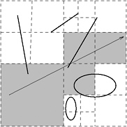
Figure 1.13: The same scenario utilizing an octree.
How do we traverse an octree along a given ray? As in the case of a grid, we have to make horizontal steps, which actually advance along the ray. With octrees, though, we also need to make vertical steps, which traverse the octree up or down.
All algorithms for ray shooting with octrees can be classified into two classes:
-
Bottom-up: this method starts at that leaf in the octree that contains the origin of the ray; from there, it tries to find that neighbor cell that is stabbed next by the ray, etc.
-
Top-down: this method starts at the root of the octree and tries to recurse down into exactly those nodes and leaves that are stabbed by the ray.
Here, we will describe a top-down method [Revelles et al. 00]. The idea is to work only with the ray parameter in order to decide which children of a node must be visited.
Let the ray be given by
and a voxel v by
In the following, we will describe the algorithm assuming that all d i > 0; later, we will show that the algorithm works also for all other cases.
First, observe that if we already have the line parameters of the intersection of the ray with the borders of a cell, it is trivial to compute the line intervals halfway in between (see Figure 1.14):
| (1.2) | |
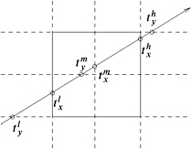
Figure 1.14: Line parameters are trivial to compute for children of a node.
So, for eight children of a cell, we need to compute only three new line parameters. Clearly, the line intersects a cell if and only if max ![]() < min
< min ![]() . The algorithm can be outlined as follows :
. The algorithm can be outlined as follows :
traverse( v , t l , t h ) compute t m determine order in which sub-cells are hit by the ray for all sub-cells v i that are hit do traverse( v i , t l t m , t m t h ) end for
where t l t m means that we construct the lower boundary for the respective cell by passing the appropriate components from t l and t m .
To determine the order in which sub-cells should be traversed, we first need to determine which sub-cell is being hit first by the ray. In 2D, this is accomplished by two comparisons (see Figure 1.15). Then the comparison of ![]() with
with ![]() tells us which cell is next.
tells us which cell is next.
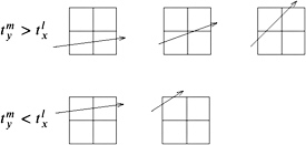
Figure 1.15: The sub-cell that must be traversed first can be found by simple comparisons. Here, only the case
In 3D, this takes a little bit more work, but is essentially the same. First, we determine on which side the ray has been entering the current cell by Table 1.1.
| max | Side |
|---|---|
| | YZ |
| | XZ |
| | XY |
Next, we determine the first sub-cell to be visited by Table 1.2 (see Figure 1.16 for the numbering scheme). The first column is the entering side determined in the first step. The third column yields the index of the first sub-cell to be visited: start with an index of zero; if one or both of the conditions of the second column hold, then the corresponding bit in the index as indicated by the third column should be set.
| Side | condition | index bits |
|---|---|---|
| XY | |
|
| | 1 | |
| XZ | |
|
| | 2 | |
| YZ | | 1 |
| | 2 |
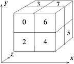
Figure 1.16: Sub-cells are numbered according to this scheme.
Finally, we can traverse all sub-cells according to Table 1.3, where ex means the exit side of the ray for the current sub-cell.
| current sub-cell | exit side | ||
|---|---|---|---|
| YZ | XZ | XY | |
|
| 4 | 2 | 1 |
| 1 | 5 | 3 | ex |
| 2 | 6 | ex | 3 |
| 3 | 7 | ex | ex |
| 4 | ex | 6 | 5 |
| 5 | ex | 7 | ex |
| 6 | ex | ex | 7 |
| 7 | ex | ex | ex |
If the ray direction contains a negative component(s), then we just have to mirror all tables along the respective axis (axes) conceptually. This can be implemented efficiently by an XOR operation.
EAN: N/A
Pages: 69