Access 2007 VBA Programming 101
Many people first enter the world of programming by creating simple Access applications that become a success and must be expanded. These programmers typically have little to no formal experience in designing software applications and have taught themselves how to write basic Access applications. They now need to use VBA to extend those applications. You may very well fall into this category. The rest of this chapter will provide you with a basic overview of general programming concepts such as the phases of the Systems Development Life Cycle and will explain how Access VBA fits into each of these phases.
All applications should be written according to a development methodology that provides guidelines for developing the application. A commonly followed development methodology is a Systems Development Life Cycle (SDLC), which includes the following phases:
-
Requirements gathering
-
Designing
-
Developing
-
Testing
-
Implementing
These phases are discussed in detail below.
| Tip | Various other types of application development methodologies can be used in addition to, or instead of, the Systems Development Life Cycle as appropriate, such as Rapid Application Design (RAD) techniques, Extreme Programming techniques, and so on. |
Requirements-Gathering Phase
In the requirements-gathering phase, your goal is to identify the objectives for the new application. The final output of the requirements-gathering phase should be a document describing the purpose of and features requested for the new application and any other helpful details you gathered during this phase.
You should determine the purpose of the application overall, who will use the application, from what locations the application will be accessed, and exactly what features the application should provide. Interview end users and other company employees as appropriate to determine what electronic or paper systems this application will replace. Ask them questions about the problems with the current systems, so you can better understand what will make your application successful. You should also find out from the end users what features they would like to see included in the application, which features they feel are critical, and which are less so. Also obtain copies of any current documents or screens of current applications or processes that are being used. Reviewing the existing applications that your application will replace is a very helpful strategy.
Interviewing end users is a critical part of developing a software application because if you expect someone to use your application you have to first find out what he is looking for. If your application does not meet some need he has, he has no incentive to use it. You should also know, however, that end users often ask for many more features than you can or should include in the application. You have to learn how to prioritize the features and implement those that are required or helpful for meeting the needs of most users or that are required in order to comply with management orders.
For purposes of illustrating some concepts in the Systems Development Life Cycle, I use a hypothetical example. Suppose that you have the task of writing a Wrox Auto Sales Application that will be used by sales and other staff at the auto sales company. Applying these requirements-gathering techniques, you have determined that the application should allow the users to search inventory for available and sold cars, to view or edit details about a selected car, and to view or edit customer details. Currently this process is being implemented solely on paper and needs to be automated in an Access application that will be used by a few end users. You have written down extensive details about what data elements need to be tracked, the features that are desired, and other details that you learned in this process. You are ready to move into the design phase.
Design Phase
During the design phase, you analyze the requirements gathered in the prior phase and determine a system design. The final output of the design phase should be a written document describing the features your application will provide and, ideally, a prototype of each screen.
You can document your design for the hypothetical Wrox Auto Sales Application and any other application in various ways, but having some type of documentation on paper before writing the first line of code is very important. You will understand why momentarily.
Start the design phase by organizing the requirements into logical groupings and/or steps. They will help you determine the layout for screens and the code. Using the Wrox Auto Sales example, let’s look at some ways you can use modeling to assist you with your design.
Model the Application Design
Modeling is best defined as the process of documenting one or more parts of an application on paper (or with an electronic tool). A variety of modeling techniques can be used to accomplish the end result: modeling the flow of activities through the system, modeling the way the code will be structured, and so on.
Regardless of the modeling techniques you decide to use, the objective is to come up with a complete roadmap for building the system before you write a single line of code. If you start coding a solution without a roadmap, you will find that it becomes extremely difficult and inefficient to make major adjustments. Think of the roadmap as a blueprint for building a house. You wouldn’t want to build a house without a blueprint showing how it is supposed to be structured. Suppose that you have someone build a house for you without a blueprint, and you check up on the progress a few weeks later. When you walk into the house, you notice that it has no basement. The first and second floors have been framed, yet there is no basement (and you wanted one). Think of how much work is involved in having all of the framing for the first and second floors torn down just so the basement can be put in. The rework involved, the cost, and the delays are enormous.
This same concept applies to designing a computer application. If you plan up front how the application needs to look and what it will do, you have a detailed roadmap. You probably won’t get deep into the process and discover some major unresolved issue. This is not to say that proper modeling will take away all risk of later problems, because that is impossible. However, you will, at least, get the major framework of the system (such as whether the house needs a basement) defined, and you can worry about finishing the very minor details (like paint colors) later. I hope you now see why documenting the system on paper before writing code is so important. Now you’ll take a look at some of the most commonly used diagramming techniques - Use Case Diagrams and Activity Diagrams - and see how they can be used to help design your applications.
Use Case Diagrams
Use Case Diagrams show the services provided by the system to its users. I like to think of it as the actions a user can take in the system. For example, in the case of the Wrox Auto Sales hypothetical application, the auto sales staff will need some type of Search Inventory Screen to allow them to search the inventory of cars. From that screen, they need to be able to run searches, clear the search results, open a selected car detail record, open the car detail screen (empty), or open the customer screen (empty). Suppose that each of these is an action the user can take on the Search Inventory Screen in the system. Thus, each of these actions can map to an action in a Use Case Diagram.
First, let’s look at how such a Use Case Diagram would appear on the screen (see Figure 1-1), and then you can study in more detail how it is structured.
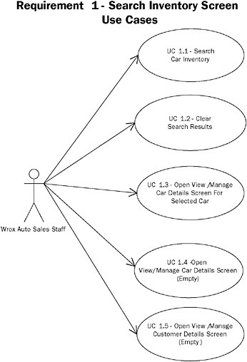
Figure 1-1
Notice how the Use Case Diagram in Figure 1-1 lists the separate actions the Wrox Auto Sales Staff can take on the Search Inventory Screen in the system, as described previously. The stick figure representing a person is called an Actor. The actor represents the Wrox Auto Sales Staff member who is using the system. Lines are drawn to each of the actions the actor can perform. No special requirement exists for how you group Use Cases. In other words, whether you group Use Cases together by screens, major functionality, logically related concepts, and so on is up to you. In the preceding example, I have structured the Use Cases by a particular screen. This is the structure that I use most frequently, as it is typically easier to think of activities you can perform in an application from the perspective of the particular screens on which they can be invoked.
Notice how each of the Use Cases is numbered beginning with the Requirement Number followed by the Use Case Number (for example, 1.2 for representing the second Use Case in Requirement One). This is another technique that I myself follow because it makes numbering Use Cases much easier should you later insert or delete one in a particular section. For example, if you add a new action that the user is allowed to perform on the Search Inventory Screen, you don’t have to renumber all the Use Cases for the entire system. You just add the next highest Use Case for that particular requirement (for example, the new one would be UC 1.6 for the preceding example).
This is the basic concept of the structure of Use Cases. So now, take a look at the Use Case Diagram for another screen in the system. Figure 1-2 shows the activities the user performs on some type of View/Manage Car Details Screen.
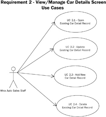
Figure 1-2
These two sample Use Case Diagrams cover several of the actions that our hypothetical Wrox Auto Sales Application will allow a user to take in the system. In Chapter 4, you will learn how the Use Case Diagrams can help create Class Diagrams to represent how source code should be structured into custom objects that you will create. Now, look at creating Activity Diagrams to portray the flow of actions in the system.
Activity Diagrams
Activity Diagrams are diagrams very similar to process Flow Diagrams, showing the flow from activity to activity and action to action. They provide a detailed view of the way a user (an actor) can operate within the system. Here are some basic steps for creating an Activity Diagram:
-
Determine the scope you want your Activity Diagram to portray (that is, a single Use Case, a series of Use Cases, a business process, a screen, and so on).
-
Add the Starting Point for the diagram.
-
Add the activities for each step users can take. This includes the initial step (opening the screen, and so on) plus any steps describing what they do next.
-
Add the Connectors from each activity to the next.
-
Label alternative paths appropriately so you can tell that the user can take one or more paths. These are called Decision Points.
-
Add any Parallel Activities, or activities that can happen simultaneously and must both finish before another action can be taken.
-
Add the Ending Points, which are the one or more points in the flow that the actions may end.
Activity Diagrams are helpful for many reasons, including aiding in structuring your code for the system and aiding in the test cases for the functionality you must ensure the system provides.
You will now see how we can apply these concepts to creating an Activity Diagram for the Search Inventory Screen of the hypothetical Wrox Auto Sales application. Based on the requirements you have gathered and analyzed so far, you have enough information to describe the actions a user can take on this screen in plain English. First, the Search Inventory Screen opens. Next, the user can open the View/Manage Car Details Screen, open the View/Manage Customer Details Screen, or run a search against inventory. If she opens the View/Manage Car Details Screen, the flow on this Search screen ends. If she opens the View/Manage Customer Details Screen, the flow on this screen also ends. However, the user can also run a search, fill in the search criteria, click the Search button, and view the results. She can then clear the results, run the search again, or open the detail screen for a selected car. After she finishes searching (or if she opens a car detail record), the flow on this screen ends. Figure 1-3 shows how these steps can be depicted in an Activity Diagram.
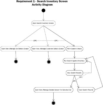
Figure 1-3
Notice how the alternative paths the user can take are depicted using OR. Further, notice how each activity is connected with an arrow. The starting and ending circles depict the points where the flow starts and the points where the flow can end. That’s really all there is to creating an Activity Diagram. You simply model the flow of the actions a user takes in the system electronically or on paper in the order they happen, indicating any alternative or parallel activities. I used Microsoft Visio to create these diagrams, but you can use various other tools or just diagrams written on paper. The tool you use is not important, just as long as you document the design in some fashion. Let’s look at an Activity Diagram for another screen in our Wrox Auto Sales application.
Figure 1-4 demonstrates the actions a user can take in order on a View/Manage Car Details Screen. Notice how the user can either open a car detail record or add a new car detail record when the screen first opens. After a record is opened, it can be viewed, modified, or deleted.
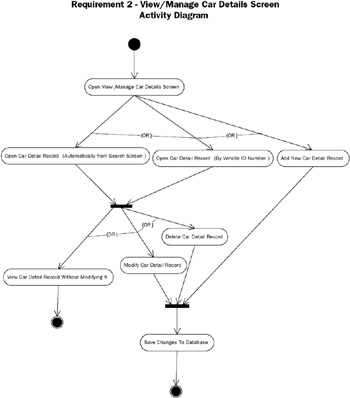
Figure 1-4
Screen Prototypes
After creating Use Case and Activity Diagrams (or other appropriate design diagrams), you should also create screen prototypes that illustrate at a basic level how the user interface will look.
Turning now to the Wrox Auto Sales hypothetical, look at what the Search Inventory and Manage Cars screen prototypes might look like. From the Use Case Diagram for the Search Inventory screen (shown in Figure 1-1), you know there are five requirements:
| | UC | 1.1 Search Car Inventory |
| | UC | 1.2 Clear Search Results |
| | UC | 1.3 Open View/Manage Car Details for Selected Car |
| | UC | 1.4 Open View/Manage Car Details Screen (Empty) |
| | UC | 1.5 Open View/Manage Customer Details Screen (Empty) |
Use Cases can translate directly into menu options, buttons, and other controls on corresponding form(s).
Figure 1-5 shows an example of how these Use Cases were mapped to user interface elements for the Search Inventory Screen. Notice how the Use Cases are satisfied: Search button (UC 1.1), Clear button (UC 1.2), Manage Cars Screen option in View menu (UC 1.3 and UC 1.4), and Manage Customers Screen option in View menu (UC 1.5). Depending on whether a particular car is selected in the search results list, the Manage Cars Screen will open empty or containing data for the selected car. The other controls you see in Figure 1-5 are the data elements that the user can specify to run a search. These data elements include Vehicle ID Number, Year, Make, Color, Model, and Status. These data elements were originally determined in the requirements-gathering phase.
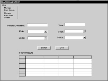
Figure 1-5
The same concepts apply to creating the View/Manage Car Details screen prototype for the hypothetical Wrox Auto Sales application. Recall that the Use Case Diagram in Figure 1-2 listed four requirements: UC 2.1 - Open Existing Car Detail Record, UC 2.2 - Updated Existing Car Detail Record, UC 2.3 - Add New Car Detail Record, and UC 2.4 - Delete Existing Car Detail Record. Figure 1-6 shows how these requirements can map to control buttons and other options on a screen. Notice how these Use Cases are satisfied in Figure 1-6: the Lookup button (UC 2.1), the Save button (UC 2.2), the Add New button (UC 2.3), and the Delete button (UC 2.4). Again, the data elements are also listed, such as Vehicle ID Number, Make, Model, and Year - all determined during the requirements-gathering phase.
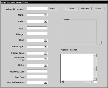
Figure 1-6
Determine Application Architecture
During the design phase, you should have determined the architecture of your application. Let’s now take a brief look at what application architecture actually is. Application architecture refers to the way you split up an application into smaller pieces. Just about all applications, including Access 2007 VBA applications, have the following elements:
-
User Interface – The screens the user sees and interacts with
-
Business Rules – The processing that takes place in response to the user’s action, such as calculating some result, looking up information, and so on
-
Database – A physical data store for certain information used by the application
The architecture is the manner in which you put all the pieces together to form an application. Often, the architecture of an application is referred to by the number of tiers it contains. In this context, tiers refers to the number of machines that an application actually runs on. If any part of an application runs on a particular machine, that machine is counted in the tiers. This concept will be described in much more detail as you look at the different types of architecture: single-tier, two-tier, and three/n-tier.
| Tip | Most of the examples in this book will be based on a single-tier standalone architecture for the sake of simplicity, although some two-tier client-server examples will also be covered. |
Single-Tier (Standalone)
Single-tier applications became common at the beginning of the PC era, but they have actually been around longer than that. A single-tier application is one where the entire application is contained and runs on a single computer. This is also referred to as a standalone application. An example of a standalone application is, of course, a Microsoft Access application that has the user interface, business logic, and data all within the same file on one computer.
An application need not be completely contained in a single file to be considered standalone. Take, for instance, a loan amortization program installed on your computer that has an .exe file that runs and reads information from one or more files on your hard drive. The entire application runs on a single computer even though more than one file is involved. This application is also a standalone application. Figure 1-7 illustrates a diagram of a typical standalone application.
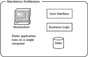
Figure 1-7
With a standalone application, everything is nicely self-contained. If you are the only person who will use the application and data, a standalone architecture is fine. In the case of Access applications, you may also put the single Access file containing both the user interface and the database on the network to allow multiple people to access the application. This works fine in many situations and also qualifies as a standalone architecture. As the number of users for a standalone Access application grows, the standalone architecture can become problematic because each user is accessing the same file on the network for the user interface and database. Many of the Access 2007 VBA examples covered in this book are based on a standalone architecture.
As applications grew and had to be shared more often, a client-server architecture was introduced to facilitate sharing. You will see how the client-server architecture can help address some of the limitations of the standalone architecture.
Two-Tier (Client-Server)
Client-server applications (applications that span two-tiers: a client machine and a server machine) solved the problem introduced by standalone applications and allowed multiple people to share the same data more easily. Client-server applications require a central server to hold the data store in a central location. The database server then processes requests for data from each of the client machines. Client-server applications first appeared in the early 1990s on the PC platform. A diagram of this architecture is depicted in Figure 1-8.
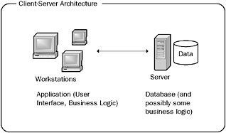
Figure 1-8
In this architecture, the data store is abstracted from the client. The client machine makes a request from the server to add, insert, update, or view data, and the server processes the request and returns the results to the client. A typical database server in such a scenario might be an Access, SQL Server, or Oracle database. In the case of an Access client-server application, the user interface may reside in one Access file, and the database may reside in a separate file or database application on a server, such as an Access or SQL Server database. Creating client-server applications using Access or SQL Server databases will be discussed in Chapters 7, 10, and 4.
In a client-server application, the main application is loaded on each client computer. The application includes the user interface and probably most or all of the business logic elements. In other words, the application contains code to create the user interface, process the user actions, perform any validations or calculations, and look up or modify data in the database. It is possible, however, to have some of the business logic on the database server, such as in stored procedures that are described in Chapters 10 and 14. For example, if you require a zip code to be five characters in length, you could put that logic in the insert or update stored procedure to raise an error instead of the code on the client. The bottom line with business logic in client-server applications is that it can be entirely on the client, entirely on the server, or you can use a combination of the two.
The advantages of client-server applications are that you can share data across multiple computers more easily than before and also separate the user interface from the database. Each client always updates the central repository.
At some point, however, the central database server is limited in terms of how many users it can handle. This might mean that a database server must scale up to a bigger server or beef up the resources of the existing server. To address some of these problems with growth and maintenance, the three-tier/n-tier architecture was introduced.
Three-Tier/N-Tier
The three-tiered architecture addresses the limitations imposed by the client-server architecture and allows you to architect solutions that can grow easily as your needs grow. The three-tiered architecture is sometimes called n-tier because it can have more than three tiers in certain situations. With three-tier and n-tier applications, you can simply add additional servers to handle the processing. Microsoft Access is not typically used to create three-tier applications, although with some complex coding it can be used as part of a three-tier application design. Access should not be used for three-tier applications because for such a large-scale application, Access is not the best user interface or database to use. It contains serious limitations.
Even though you will not use Access to develop three-tier applications, it is still worthwhile to understand what a three-tier application includes. I discuss this because, at some point, you may need to migrate your client-server Access application to a three-tier architecture.
So, how does a three-tier architecture create incredible growth potential? The idea is that application elements are physically compiled as separate elements, and they run on different computers. For example, the user interface elements are separate from the middle-layer business logic, which is separate from the database layer. In this case, the application is running on three different computers: the client, the middle-tier server, and the database server (hence the name three-tier). Figure 1-9 diagrams this.
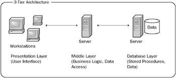
Figure 1-9
The three-tier/n-tier architecture takes client-server to the next level by abstracting all the various layers of processing from both the client and the server. It takes some practice to do this correctly. In plain English, what does this mean to you as a programmer? It means that you break the application into isolated pieces that call each other as appropriate. You no longer write a single program with intermixed code that creates the user interface, checks the business rules, performs calculations, and updates the database.
When these actions get split into separate functionalities, they can be thought of as separate source code projects. You create the part of the program that deals specifically with showing the graphical user interface in its own project (such as an .exe created using Visual Basic or Visual Basic .NET). You then create the business logic in its own project that will be compiled into a business logic component (such as a DLL created using Visual Basic or Visual Basic .NET). The business logic component will then be called by the client project to perform any calculations, business rules checks, and so on. The brief summary below states this idea another way.
The presentation layer is responsible for:
-
Displaying the user interface
-
Processing user requests
-
Sending user requests to the middle (business) layer for processing
-
Receiving results of the user requests from the middle (business) layer
-
Presenting the results of the requests to the user
The presentation layer can be a Web browser interface (thin client) or a traditional non-Web-based (rich client) user interface. Thin client refers to the fact that very little, if any, compiled code is installed on the client for rendering the user interface. Rich client refers to the fact that a fair amount of compiled code is installed on the machine to make the interface richer to the user. Either way, thin or rich client, the user interface elements are still separated from the other layers.
The middle (business) layer is responsible for:
-
Receiving requests from the presentation layer
-
Performing any business logic checks or calculations
-
Interacting with the data (database) layer
-
Returning the processed results to the presentation layer
The data (database) layer is responsible for:
-
Storing the data
-
Returning data upon request to the middle layer
-
Modifying data upon request from the middle layer
This three-tier/n-tier architecture allows each processing layer to be built as a set of components (sometimes called objects) that can be called very efficiently from a large number of clients.
In addition to isolating the business logic from the presentation and database layers, it is also very common to further separate any call to the database into its own layer, as shown in the diagram in Figure 1-10.
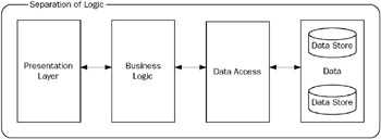
Figure 1-10
Using this approach, the summary of the actions performed by each layer is modified as follows:
The presentation layer is responsible for:
-
Displaying the user interface
-
Processing user requests
-
Sending user inputs to the Business Logic Layer for processing
-
Receiving results of the user requests from the Business Logic Layer
-
Presenting the results of the requests to the user
The business logic layer is responsible for:
-
Receiving requests from the presentation layer
-
Performing any business logic checks or calculations
-
Returning the processed results to the presentation layer
The data access layer is responsible for:
-
Receiving requests from the business logic layer
-
Interacting with the data (database) layer
-
Returning the processed results to the business logic layer
The data (database) layer is responsible for:
-
Storing the data
-
Returning data upon request to the data access layer
-
Modifying data upon request from the data access layer
Separating Code into Logical Tiers
Although the idea of separating your code into different tiers was just described in the context of designing three-tier enterprise applications, be aware that you can write your Access 2007 VBA applications in multiple logical tiers to make future migrations easier. I will show you why.
For example, if you isolate all code that will touch the database for an add, update, delete, or retrieval of data into its own separate component or module (totally separate from the business logic), it is much easier to change from one database platform to another. Suppose that you decide to switch from Access to SQL Server as the database. With the database access code isolated in a single module, you only have to modify the data access components and the database itself. You do not have to touch any of the presentation (user interface) code or the business logic code. Imagine how much easier this is than weeding through dozens of procedures unrelated to database access to find what must be modified for the new database platform.
Although you organize the application into separate modules or components, you may not actually run them on separate servers. For example, you may have written a module (such as a VBA module) for all of the business logic and a separate module (such as a VBA module) for handling all data access calls to the database. Although those modules are in separate logical tiers, they may run on the same server (the physical tier). The beauty is that by structuring your Access code properly now, you prepare for future growth if later you decide to migrate to different servers or implementations. Various chapters throughout this book will illustrate these preferred design techniques in detail to make your future modifications and migrations easier.
Now that I have covered how to document your application into a written specification and to determine the appropriate architecture, let’s move on to the next phase of the SDLC.
Development Phase
After you have completed the design phase and have a written specification for how your application should function and look, you enter the development phase. Here you begin using Access 2007 and Access 2007 VBA to create your application according to the design specifications you just created. As you are probably already aware, you use Forms in Access to create the user interface. You should use VBA to create the code for the business logic and data access logic. You should use a database such as Access or SQL Server to store the database tables and records.
Because this is a book about VBA, I show you how to write VBA code for the business logic and database access logic using the Visual Basic Editor. Let’s take a look at some simple examples in the Visual Basic Editor.
The Visual Basic Editor
As previously mentioned, VBA code is written in Access using the Visual Basic Editor. You can get to the Visual Basic Editor in various ways. One way is to select the Database Tools ribbon, and then select the Visual Basic icon in the Macro group, as shown in Figure 1-11.
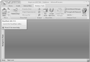
Figure 1-11
You can also select Alt+F11 to open the Visual Basic Editor. Yet another way to get to the Visual Basic Editor in Access is to select the Create ribbon, select the drop-down list for Macro, and then select Module from the list. This is shown in Figure 1-12.
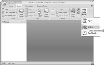
Figure 1-12
Figure 1-13 shows an example of what the Visual Basic Editor looks like.
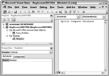
Figure 1-13
Notice that the Visual Basic Editor in Figure 1-13 contains a Code window on the right side, a Project window on the upper-left side, and a Properties module on the bottom-left side. The way these windows are arranged can be customized to suit your preferences. Additional windows can also be displayed by using the View menu.
What you see in the Visual Basic Editor depends on how you got there and what objects are part of the Access database already. The concept of Access objects will be described in detail in Chapter 3. For now, just think of forms, controls, modules, and examples of potential objects that may have VBA code associated with them. In the Project window of Figure 1-13, a new module called Module1 was just inserted. The cursor is flashing in the code window that is associated with Module1. When other objects are present in the Project window, you can navigate through the hierarchy and use the Code window to add or modify code that corresponds to the selected objects.
For example, suppose that you have a form in your Access database called frmMain. You have added a command button called cmdText to your frmMain. You can get to the Visual Basic Editor from within frmMain by first selecting the cmdText control and then selecting an event, such as On_Click, as shown in Figure 1-14.
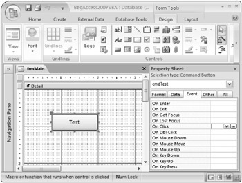
Figure 1-14
Next, click the button with the ellipses (…) to open the screen shown in Figure 1-15.
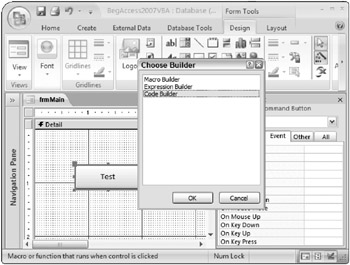
Figure 1-15
On the Choose Builder screen shown in Figure 1-15, select the Code Builder option and then click OK. The Visual Basic Editor is then opened with a new empty procedure for the cmdTest_click event in the Code window, as shown in Figure 1-16.
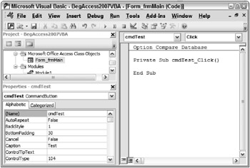
Figure 1-16
Notice how you now see the frmMain Form in the Project window in the upper-left side of the screen as well. Let’s look at a few examples of how you can add code to the Code window using the cmdTest_click event as an example. If you begin typing a command in the code window, such as the msgbox command, a tooltip appears (where available and appropriate) to provide you with details on the syntax required for that command. An example of this is displayed in Figure 1-17.
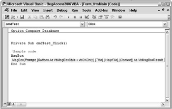
Figure 1-17
Another helpful feature of the Visual Basic Editor helps you complete a particular command by displaying a list of available options. An example of this feature is shown in Figure 1-18.
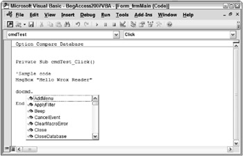
Figure 1-18
Notice in Figure 1-18 how the docmd command has been entered followed by a period. The moment you type the period, the available options for docmd are displayed. You can then select one of the available options from the list. In the development phase, you use the Visual Basic Editor to write the code to implement the business logic and database logic for your forms.
After you have developed all or part of your code, you enter the testing phase.
Testing Phase
In the testing phase, you test the application to ensure it works. Testing is an iterative process. For example, unit testing should be performed as different parts of the application are completed. Also, system tests at the end should be completed to ensure that various parts of the system work correctly together. To test the code you create using the Visual Basic Editor, you can use various techniques, as I describe in the following sections.
Running and Debugging Code in the Visual Basic Editor
The Visual Basic Editor allows you to compile, run and debug your VBA code. The steps involved in running and debugging your application are illustrated in detail in Chapter 2 in the Debugging section. However, to give you just a few examples of how the testing phase works, look at some of the types of techniques you can use to test your code.
As shown in Figure 1-19, breakpoints can be added to particular lines of code so that execution stops when that line is reached. Breakpoints can be set at various places in your code so that you can stop on selected lines of code to analyze various aspects of the application at that particular time.
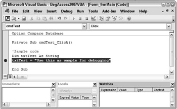
Figure 1-19
Notice how in Figure 1-19 and Figure 1-20, the screen includes Immediate, Locals, and Watches windows. The Immediate window allows you to obtain information at a particular point in time, such as when a breakpoint is encountered. In the example in Figure 1-20, the current value of the txtTest variable was retrieved using the Immediate window by typing ? txtTest in the window just after running the line of code that set the value of the variable. In the Locals window, you can see that all variables of the current procedure are displayed, which in this example is the txtTest variable. The Watches window is currently empty but allows you to establish rules for watching certain activities as they occur.
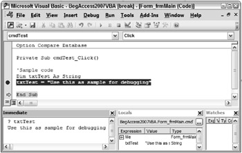
Figure 1-20
As mentioned previously, these testing techniques and several others will be covered in the debugging section of Chapter 2. For now, just be aware that you write your VBA code in the Visual Basic Editor according to your design specifications. The Editor has various features that allow you to run, test, and fix your VBA code for the application. You will be using the Visual Basic Editor throughout the entire book, so you will become very familiar with how it works.
Implementation Phase
After you complete the testing phase and have corrected your application, you enter the implementation phase. In this phase, you distribute the application to the end users. In Access, there are various ways to distribute your application, as I discuss in detail in Chapter 10.
After you implement the application, some or all of the phases discussed herein can be repeated as necessary, for example when the existing features are being maintained or new features are being added.
EAN: 2147483647
Pages: 143