11.2 UML Diagrams
11.2 UML Diagrams
The UML language provides a set of syntactic and semantic rules for representing the system in a semigraphical form. UML is an expressive visual modeling tool to help develop and express meaningful models. The UML modeling language does not include a develop methodology for constructing object-oriented applications.
The UML includes a collection of diagrams; each one describes a different view of an application or system. The diagrams are:
-
Use case diagrams
-
Class and object diagrams
-
Object interaction diagrams
-
Sequence diagrams
-
Collaboration diagrams
-
-
State diagrams
-
State diagrams
-
Activity diagrams
-
-
Implementation diagrams
-
Package diagrams
-
Component diagrams
-
Deployment diagrams
-
Often, only a subset of these diagrams is needed to completely model an application. The most relevant UML diagrams are described in this chapter. The UML stereotype provides an extension mechanism to the UML that allows users to extend the modeling language according to their needs. Two examples of stereotypes are ≪actor≫ and ≪active≫, which are used in the following subsections.
11.2.1 Use Case Diagrams
These diagrams define the interactions between users and an application. The use case diagrams describe the main functionality of the application and its interactions with external entities called actors. A UML actor is a user, an external system, or external hardware. Such an interaction is a way that a user or an external entity can use the application. Each one of these interactions is represented by a use case.
Use cases are triggered or initiated by actors and describe the sequence of events that follow. Use case diagrams define the major processes of a system and the boundary on the problem. The diagrams also define who (or what) will use the application, and define the interactions that are allowed.
Typically, an application consists of one or more use cases, which are the processes within the application. These processes are represented as ovals, with the names inside the ovals. The application or system is represented by a rectangle, with the name of the application inside the rectangle. A line joining the actor and the use case represents the communication between each actor and its corresponding use case. An actor is shown in one of several ways; the most common is by using the stereotype ≪actor≫.
Figure 11.1 shows a use case diagram for the movie rental application. There are two use cases in this example. The actors are the users of the system, who interact with the application by starting to search for a movie or by renting a movie to a customer.
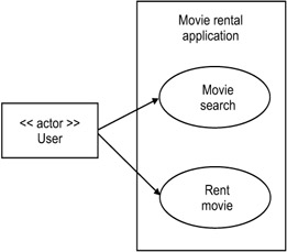
Figure 11.1: A use-case diagram for the movie rental application.
The use cases are identified in the first part of the analysis phase of the software development process. They serve to define the user requirements.
EAN: 2147483647
Pages: 184