M160 Internet Router
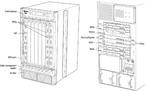
| The M160 Internet router (see Figure 3.21) has a maximum aggregate throughput of 160 Gbps. It accepts up to eight FPCs and offers a high level of redundancy so that no single point of failure can cause the entire system to fail. Table 3.12 shows the physical specifications of the M160 router and Table 3.13 gives an overview of the major hardware components of the router. Figure 3.21. M160 Internet Router Chassis and Components Table 3.12. M160 Internet Router Physical Specifications
Table 3.13. M160 Internet Router Major Hardware Components
The router chassis includes two front support posts to attach the router to a front-mount rack, two mounting ears for center-rack mounting, and two ESD points, one at the front and one at the rear. The midplane is located in the center of the chassis and forms the rear of the FPC card cage. The FPCs install into the midplane from the front of the chassis, and the SFMs, Routing Engines, MCSs, and PCGs install into the midplane from the rear of the chassis. The power supplies and cooling system components also connect to the midplane.
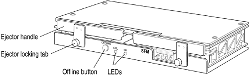
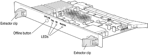
The Switching and Forwarding Modules (SFMs) (see Figure 3.22) provide route lookup, filtering, and switching to the destination FPC. Up to four interconnected SFMs can be installed in the router, providing a total of 160 Mpps of forwarding. Figure 3.22. M160 SFM The SFM is a two-board system; its components include Distributed Buffer Manager ASICs, which send packets to the output buffer and forward notification to the I/O Manager ASICs on the FPCs, the Internet Processor II ASIC, which performs route lookups, 8MB of parity-protected SSRAM, a processor subsystem that handles exception packets and management of the SFM, two LEDs, and an online/offline button for removing and installing the SFM. The FPCs install vertically into the midplane from the front of the chassis. The FPCs are numbered left to right, from 0 through 7. Each FPC accepts up to four PICs. The FPCs connect the PICs to the rest of the router so that incoming packets can be forwarded across the midplane to the appropriate destination port. FPCs contain shared memory, which is managed by the Distributed Buffer Manager ASIC on each SFM, for storing data packets received by the PICs. The I/O Manager ASIC on each FPC divides incoming data packets from the PICs into cells , which are stored in a shared memory buffer, and reassembles them into data packets when they are ready for transmission. The components of the FPC include the I/O Manager ASICs, which parse Layer 2 and Layer 3 data and perform encapsulation and segmentation; the Packet Director ASICs, which distribute incoming packets to the I/O Manager ASICs and direct outgoing packets from the I/O Manager ASIC to the PICs; 32-MB SDRAM DIMMs, which form the shared memory buffer for the router; parity-protected SSRAM, which stores data structures used by the I/O Manager ASICs, a processor subsystem; two LEDs; and an offline button, located on the craft interface, for removing and installing the FPC.
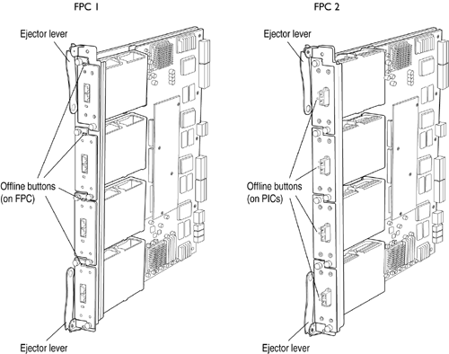
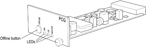
The router supports two types of FPC: FPC1, which supports PICs including single-port OC-12 and Gigabit Ethernet, and FPC2, which supports higher-speed PICs including OC-48 and Tunnel Services. The router can operate with any combination of FPC1s and FPC2s installed. The installation and removal of the two FPC types are identical. PICs that can be inserted on an FPC2 are distinguished by having an offline button on their faceplate. The FPC1 has built-in offline buttons for the PICs it holds (see Figure 3.23). In this guide, both the FPC1 and FPC2 are referred to simply as "FPC" except where the differences between the two are being discussed. Figure 3.23. M160 FPCs FPCs are hot-insertable and hot-removable. When you bring an FPC online, the Routing Engine downloads the FPC software, the FPC runs its diagnostics, and the PICs on the FPC slot are enabled. No interruption occurs to the routing functions. The router has two PCGs, located in the rear of the chassis to the right of the Routing Engine slots (see Figure 3.24). The PCGs supply the 125-MHz system clock to the Packet Forwarding Engine components. Figure 3.24. M160 PCG The PCGs both send clock signals to the Packet Forwarding Engine modules, along with a signal indicating which is the master clock source. The master Routing Engine controls which PCG is master and which is backup. The components of each PCG include a 125-MHz system clock generator, three LEDs, and an online/offline button for removing and installing the PCG. The router can have one or two host modules. The host modules provide the routing and system management functions of the router, and provide the clock source for SONET/SDH interfaces.
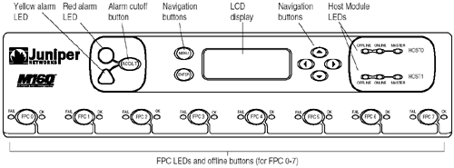
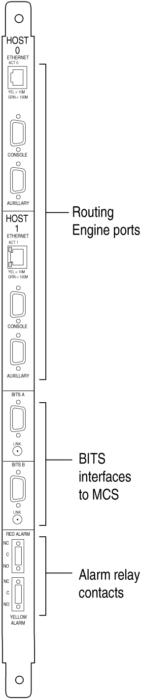
Each host module consists of a Routing Engine and an MCS installing in adjacent slots. For each host module, the Routing Engine and MCS function as a unit, each component requiring the other to operate; if the adjacent component is not present, a Routing Engine or MCS will not operate, even if physically installed in the router. The M160 router can have one or two Routing Engines. The Routing Engines install into the upper rear of the chassis. If two Routing Engines are installed, one functions as master and the other as backup. If the master Routing Engine fails or is removed, the backup restarts and becomes master. The Routing Engines are hot-pluggable. The Miscellaneous Control Subsystem (MCS) works with the Routing Engine installed in the adjacent slot to provide control and monitoring functions for router components and to provide SONET clocking for the router (see Figure 3.25). The MCS installs into the rear of the chassis, in the slot adjacent to the Routing Engine with which it forms the host module. Figure 3.25. M160 MCS The router can be equipped with up to two MCSs for redundancy. If two MCSs are installed, one functions as the master MCS and the other as backup. If the master MCS fails or is removed, the backup restarts and becomes the master MCS. The functions of the MCS include monitoring and controlling of router components; controlling the powerup sequence of router components at startup; powering down of components when their offline buttons are pressed; controlling mastership (in a router with redundant Routing Engine, MCS, or PCG modules); controlling FPC resets, providing the clock source for SONET/SDH interfaces; and monitoring the SONET clock, the SONET reference clocks from the FPCs, and the system clocks from the PCGs. The components of each MCS include an interface to the Routing Engine, high-speed switch for intermodule communication, a 19.44-MHz Stratum 3 reference clock for SONET/SDH PICs, three LEDs, and an online/offline button for removing and installing the MCS. The craft interface (see Figure 3.26) is located on the front of the chassis above the FPC card cage, and contains the alarm LEDs and alarm cutoff button, LCD display and navigation buttons, host module LEDs, and FPC LEDs and online/offline buttons. Figure 3.26. M160 Craft Interface The CIP, located at the left side of the FPC card cage (see Figure 3.27) consists of connectors for the Routing Engines, BITS interfaces for the MCS, and alarm relay contacts to connect the router to external alarm display devices. Figure 3.27. M160 CIP The router has two load-sharing DC power supplies, of either the original or enhanced type (see Table 3.14). The power supplies are located at the lower rear of the chassis, below the rear lower impeller and the router's on-board circuit breaker box. The power supplies connect to the midplane, which delivers the power input from the circuit breaker box and distributes the different output voltages produced by the power supplies to the router's components, depending on their voltage requirements. The router supports DC power supplies only. Power supplies are hot-removable and hot-insertable. Each power supply has handles to facilitate removal from the chassis. Table 3.14. M160 Power Supply Electrical Specifications
The power cables from the DC power source connect to the circuit breaker box, which is located on the rear of the chassis above the right power supply. The circuit breaker box provides one circuit breaker for each power supply. Power must be connected from two DC sources for load sharing, one for each circuit breaker, for proper operation of the router. Power cables are attached to the terminal studs on the circuit breaker box by cable lugs and washers . A grounding cable is attached to separate grounding points on the chassis above the circuit breaker box by bolts and washers. The router has fuses for the FPCs, SFMs, MCS, and PCGs. The fuses are located in a fuse box on the rear of the midplane. To access the fuses, you remove the rear lower impeller assembly. The router uses Cooper Bussman brand GMT-type fuses . The fuse locations are also shown on a table attached to the midplane below the fuse box.
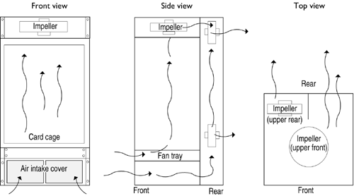
The M160 router has two separate cooling subsystems, one for the front and one for the rear. The front cooling subsystem consists of an upper impeller and a lower fan tray, which cool the FPCs, the PICs, and the midplane. The rear cooling subsystem consists of a pair of impellers, which cool the SFMs, the host module, the PCGs, and the power supplies. The air intake for both cooling subsystems is located on the front of the chassis, below the FPC card cage. An air filter in front of the air intake prevents dust and other particles from entering the cooling system. The MCS monitors the temperature of the router's components. When the router is operating normally, the impellers and fans function at lower than full speed. If an impeller or fan fails or is removed, the temperature increases and the speed of the remaining impellers and fans is automatically adjusted to keep the temperature within the acceptable range. Figure 3.28 shows air flow through the chassis and the location of the cooling system components. Figure 3.28. Air Flow through the M160 Router The M160 router's cable management system consists of a row of nine semicircular plastic bobbins, mounted on the front of the chassis below the FPC card cage. The PIC cables wrap around the bobbins, keeping the cables organized and securely in place. The curvature of the bobbins also maintains the proper bend radius for optical PIC cables. The router has LEDs that display the status of various router components. Table 3.15 lists the LEDs on the craft interface and the individual router components. Table 3.15. M160 and M40e Internet Router LEDs
| ||||||||||||||||||||||||||||||||||||||||||||||||||||||||||||||||||||||||||||||||||||||||||||||||||||||||||||||||||||||||||||||||||||||||||||||
EAN: 2147483647
Pages: 185