2. Modeling
2. Modeling
Modeling is the description of virtual and real elements of the environment in mathematical forms and as data structures. Modeling can be as simple as describing the physical dimensions of a planar image in pixels. Many applications, however, require more complex descriptions, such as 3D polygon meshes, scene graphs or constructive solid geometry trees. Modeling must capture characteristics of both the real and virtual elements in the augmentation process. A system might wish to add a billboard advertisement to video of travel on a highway. The billboard would need to be rendered from varying viewpoints as the car passes the location the billboard has been assigned to. Consequently, the billboard model will be represented using 3D modeling techniques from computer graphics [18, 19]. Additionally, characteristics of the road may result in occlusion of the billboard when some physical object, such as a bridge, passes between the viewpoint and the virtual billboard location. In that instance an occlusion model of the physical environment is required to render the occlusion area that will block the billboard. This area will vary as the viewpoint changes. Consequently, the geometry of the highway system may be modelled using 3D techniques as well.
The modeling process can be broken into two primary categories: 2D and 3D. 2D representations are usually trivial, consisting only of polygonal boundaries in source images or rectangular region description. A virtual advertisement that is to be placed into a scene need only be described as a simple image and the destination location as a quadrilateral. 3D object representations are more complex, creating a description of an object sufficient to support rendering by a graphics package and display on the computer screen or integration into the projection of a real 3D scene as captured by a camera. A realistic 3D visualization requires object representations that accurately describe all the attributes required for realistic rendering including geometry, surface characteristics and lighting. This section introduces typical methods used for modeling in augmented imagery, such as polygonal meshes, parametric descriptions and fractal construction.
For the rendered image to look "real," the augmented content should maintain the same or similar geometric and spatial characteristics as that of the original video. An augmented imagery designer's tools will often include tape measures and callipers. Surface and lighting characteristics in the virtual environment must match those in the real world. The original video often must be analyzed to acquire data required for modeling. This process is called scene-dependent modeling, which is introduced later in this section.
2.1 3D Object Representation
Ideally, augmented imagery integrates images from different sources into a seamless whole. The most common combination is of a real camera image and a virtual image rendered by a graphics system such as OpenGL or Direct3D. Therefore, 3D object representation is the first step for many augmented imagery applications. 3D object representations are used both to render the augmented elements of an image and to indicate where the pixels of the augmented content are visible. The output of the rendering process is often both an image and an alpha map, a matrix of values corresponding to pixels and indicating the transparency of each pixel. Describing an object in most graphics systems requires the specification of geometry and material. Geometric data describes the structure of the object, indicating surfaces, boundaries, and interiors; material data include appearance attributes such as surface reflection characteristics and textures. This section focuses on boundary representations for 3-D object modelling, methods that describe objects by describing the visible surfaces. Alternatives such as constructive solid geometry and volume descriptions are also used, but are beyond the scope of this chapter.
The most commonly used 3-D boundary representation is a set of surface polygons that enclose the object interior and form the "skin" of it. This collection of polygons is called a polygon mesh, a standard means of describing 3D surfaces. A polygon mesh consists of vertices and polygons and can be organized in many ways. A common organization is as a face list of polygons, with each polygon described as a vertex list and a normal list. The vertex list contains coordinate values, and the normal list contains surface orientation information for the face or vertices of the face, information useful in the shading process. Polygonal mesh representations are simple and fast, since all information is stored and processed with linear equations. Complex curved surfaces can be simulated to a high degree of accuracy through the use of shading techniques that modify the surface normals to blend shading between adjacent surfaces. Most high-performance graphics systems incorporate fast hardware-implemented polygon renderers which can display thousands to millions of shaded polygons (often triangulated) per second. Figure 13.3 illustrates a simple pyramid represented by a polygonal mesh and the corresponding vertex, normal and face list.
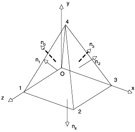
Figure 13.3: A simple polygon mesh description of a pyramid with vertex, normal and face list
| Vertex list (x, y, z) | Normal list (nx, ny, nZ) | Face list (vertices, and associated normal) | |
|---|---|---|---|
| 0 | (0, 0, 0) | (-0.897, 0.447, 0) | (0, 1, 4) (0, 0, 0) |
| 1 | (0, 0, 1) | (0, 0.447, 0.897) | (1, 2, 4) (1, 1, 1) |
| 2 | (1, 0, 1) | (0.897, 0.447, 0) | (2, 3, 4) (2, 2, 2) |
| 3 | (1, 0, 0) | (0, 0.447, -0.897) | (3, 0, 4) (3, 3, 3) |
| 4 | (0.5, 1, 0.5) | (0, -1, 0) | (0, 1, 2, 3) (4, 4, 4) |
Objects that are naturally composed of flat faces can be precisely represented by a polygon mesh. Objects with curved surfaces, such as spheres, cylinders, cones, etc., must be approximated using small polygons, a process referred to as tessellation. The object surface is divided into facets in order to achieve a piecewise approximation. The error due to tessellation is referred to as geometric aliasing. Decreasing geometric aliasing requires increasing the number of polygons, which increases the resolution of the description, but also boosts the storage requirements and processing time. If the mesh represents a smoothly curved surface, rendering techniques such as Gouraud shading eliminate or reduce the presence of polygon edge boundaries, simulating smooth surface curves with smaller sets of polygons. Figure 13.4 is a tessellated 3D object; Figure 13.5 is the same object represented with the same level of tessellation, but using Gouraud shading to improve the appearance.
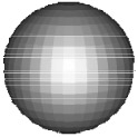
Figure 13.4: A ball represented as a tessellated polygon mesh
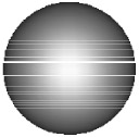
Figure 13.5: A ball rendered using Gouraud shading
Parametric representations describe curves and smooth surfaces at a higher level of abstraction, either using parameterizations of mathematical functions (for common objects such as spheres or ellipsoids) or through parameterized sets of equations such as quadratics or cubics. Common basic geometries are often described mathematically because the representation is much smaller than a polygon mesh and is not an approximation. It should be noted that the rendering process of many graphic environments, including OpenGL, converts parameterized representations to polygon-mesh approximations, anyway due to the design of rendering hardware. Quadric surfaces (second-degree equations), such as spheres and ellipsoids, are examples of functional representations, a class of parametric representations.
For complex curves and surfaces that can't be described with a single mathematical function, spline representations can be applied to model objects with piecewise cubic polynomial functions. This method is a staple of computer-aided-design (CAD) and interactive modeling tools used to describe 3D objects with smoothly varying surfaces, such as human faces or bodies. A spline representation specifies a curve or curved surface using a set of control points, which are fitted with piecewise continuous parametric polynomial functions using interpolation or approximation. Moving the control points modifies the resulting curve, so control points can be adjusted to arrive at the expected shape. There are several common spline specifications used in 3D object modeling, include Bezier, B-splines and NonUniform Rational B-Splines (NURBS). As an example, to model a Bezier surface, an input mesh of control points is specified so as to connect two sets of orthogonal Bezier curves. A two-dimensional Bezier curve generated from four control points and a Bezier surface are shown in Figure 13.6 and Figure 13.7.
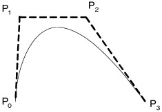
Figure 13.6: A Bezier curve with 4 control points
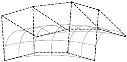
Figure 13.7: A Bezier surface
Fractal representations are commonly used to model naturally chaotic objects such as clouds, snowflakes, terrain, rock, leaves, etc., which are difficult to be described as equations of Euclidean-geometry methods because of their irregular shape or fragmented features. These objects have two common characteristics: infinite detail at every point and self-similarity between the object parts and whole features. Based on these properties, Fractal representations can generate representations of this class of objects by repeatedly applying a specified transformation function to points within a region of space. Greater level of detail with a fractal object can be obtained when more steps in the iterated function system are performed.
2.2 Scene Graph Representations
Simple polygon mesh representations are often organized hierarchically. Indeed, most complex graphic objects are built by composing other component graphics objects, with only the most primitive elements directly built from polygon meshes. Figure 13.8 is an example of how a highway billboard might be represented hierarchically in a scene graph. The billboard is built from a support structure that mounts it to the ground and a structure that serves as a surface for the advertising. Each of these elements can be designed independently, and then placed relative to each other by associating a geometric transformation (specification of orientation and relative location) with each graph edge. Likewise, the subcomponents are, in turn, built from other subcomponents.
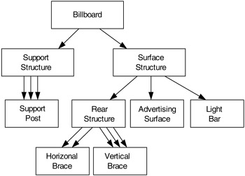
Figure 13.8: Screen graph of a highway billboard
The transformation matrix necessary to render a scene graph element in the proper location is the composition of transformations along the edge path to the graph node. Typically, only the leaf nodes will be described using primitives. Scene graphs greatly simplify the representation of complex environments.
2.3 Representation for Occlusion
The billboard example describes the representation of a graphical object that will be rendered as a virtual element in an augmented image. It is also common that models will be used to describe elements of the real image that may occlude virtual elements. As an example, a virtual insect may fly behind objects in a room. An occlusion model is a graphical model of the real environment that facilitates occlusion of virtual objects.
When the virtual object is rendered, the occlusion model is also rendered. However, the occlusion model is not subject to lighting or surface characteristics, but instead is rendered in such a way as to ensure transparency in the composition process. The most basic solution is to render the occlusion model with a transparent alpha value when generating an alpha map, an image indicating transparent and opaque regions of the result. Alpha maps are described in Section 4. Other examples include the use of a fixed background color, such as blue, that is easily segmented and replaced.
2.4 Scene-Dependent Modeling
There are often more considerations that must be taken into account than just geometrical and visual properties. Augmented imagery differs from simple image composition in that the augmented elements have geometric consistency with the real image, which makes the resulting combination look "real" rather than artificial. It is often required that the augmented imagery system analyze the original images to acquire information required for modeling, particularly when the patches will "replace" some parts in the background. Scene-dependent modeling, or image-based modeling, attempts to build three-dimensional models based on visual cues represented in two-dimensional images or image sequences. This process can be very complex, requiring computer vision methods to reconstruct underlying image content.
EAN: 2147483647
Pages: 393