Ethernet Interface Cards
| Ethernet interface cards are used in the ONS 15454 platform to enable a service provider or network operator to integrate Ethernet into the SONET/SDH bandwidth. This allows data traffic to share the same transport platform as time-division multiplexing (TDM) links. Ethernet interface cards can be used for 10-Mbps, 100-Mbps, and 1000-Mbps (or GigE) signals, as well as subrate signals for each of these interface types. Some Ethernet interface cards, such as the G-Series and CE-Series, provide transport (or Layer 1) services; other card types enable switching (Layer 2) as well as routing (Layer 3) functionality. Transport (Layer 1) Ethernet Service InterfacesLayer 1 Ethernet transport services, which are enabled using point-to-point ONS 15454 circuits, are provided using either the G-Series or CE-Series Ethernet interface cards. This type of service can also be provided using the E-Series cards when operated in what Cisco calls Port-Mapped mode. Table 6-5 provides a summary of these cards.
G-Series Ethernet Interface CardsThe G-Series interface cards are used to provide transport bandwidth for Ethernet frame forwarding between two locations in an MSPP network for point-to-point services. The bandwidth that can be allocated for linking G-Series ports is user-selectable, from a minimum of a single STS-1 up to full line-rate GigE. The G1000-4 and G1K-4 are hardware equivalents; the only difference between the two versions is XC card compatibility. The G1000-4 card is always limited to use with the XC10G cross-connect card and cannot be used in a chassis equipped with XCVT cross-connect cards. The G1K-4 card is a later version with additional flexibility. When ONS 15454 Software Release 4.0 or higher is used, the G1K-4 can be used with XCVT cross-connect cards; its use is limited to the high-speed slots (Slots 5, 6, 12, and 13). G-Series cards have four Gigabit Interface Converter (GBIC) ports on the card faceplate. GBICs are similar in concept to SFPs, but in a larger physical package and with SC fiber connectors instead of an LC pair. Figure 6-11 shows a group of GBIC modules. Figure 6-11. GBIC Modules Each G-Series card GBIC receptacle can be independently equipped with SX (short reach 850 nm), LX (long reach 1300 nm), ZX (extended reach 1550 nm), Coarse DWDM, or DWDM GBICs. Each card has an LED labeled ACT, which indicates the card's status, and an LED labeled FAIL, which remains illuminated if the card's processor is not ready or if a failure has occurred. Additionally, each of the four ports has a status LED, labeled ACT/LINK. A solid green ACT/LINK lamp indicates that a link is not carrying traffic; a flashing ACT/LINK lamp means that the link is active and carrying traffic. A solid amber ACT/LINK lamp indicates that there is link but that traffic is inhibited, such as when a circuit has not been built to the port or when the port has not been enabled. Circuits for carrying Ethernet frames are built from a single port on a G-Series card in one MSPP node to another single port on a G-Series card in another MSPP node. The G-Series cards permit contiguously concatenated circuits of certain sizes. The allowable sizes that can be accommodated in the SONET platform are STS-1, STS-3c, STS-6c, STS-9c, STS-12c, STS-24c, and STS-48c. The maximum bandwidth that can be provisioned to a single G-Series card is 48 STS-1 equivalents. One restriction exists for the circuit sizes that can be used with the G-Series cards, which could preclude the network operator from using the full 48 STS-1 bandwidth. This restriction is applicable to instances in which a single line-rate circuit (STS-24c) and one or more subrate circuits are used on the same card. In this case, the total bandwidth of the subrate circuits is limited to a maximum of 12 STS-1s. To realize the full bandwidth capability (48 STS-1s) of the G-Series card, the possible combinations are either two line-rate circuits or a combination of up to four subrate circuits with total bandwidth of 48 STS-1s. Besides Ethernet transport between two sites, there is one additional application for the G-Series Ethernet interface cards. These interfaces can also be configured for use as transponders. This would enable a conventional SX, LX, or ZX Gigabit interface to be converted to a dense wavelength-division multiplexing (DWDM) or coarse wavelength-division multiplexing (CWDM)compatible wavelength signal, and to be directly connected to a DWDM/CWDM filter system. In this mode, the traffic passing through the G-Series card does not access the cross-connect fabric; this simply provides a method for conditioning Ethernet signals for transport across an xWDM network. CE-Series Ethernet Interface CardsMuch like the G-Series, the CE-100T-8 interface card is used to provide transport bandwidth for Ethernet frame forwarding between two locations in an MSPP network for point-to-point services. The bandwidth that can be allocated for linking CE-Series ports is user-selectable, from a minimum of a single VT1.5, up to full line-rate 100Base-T Ethernet. The CE-100T-8 requires ONS 15454 software version 5.0.2 or higher and can be used in any of the 12 system traffic slots. CE-100T-8 cards have eight 10/100 RJ-45 Ethernet ports on the card faceplate. Each card has an LED labeled ACT, which indicates the card's status, and an LED labeled FAIL, which remains illuminated if the card's processor is not ready or if a failure has occurred. Additionally, each of the eight ports has an ACT LED (amber) and a LINK LED (green). A solid green LINK lamp indicates that a link exists. A blinking amber ACT lamp indicates that traffic is being transmitted and received over the link. Circuits built to connect ports on CE-100T-8 cards can be either contiguously concatenated or virtually concatenated, and either low order (VT1.5) or high order (STS-1 or STS-3c). Combinations of the various circuit types and sizes are allowed. Some example circuits include these:
Additional information on circuit sizing and CE-Series applications is provided in Chapter 7, "ONS 15454 Ethernet Applications and Provisioning." E-Series Ethernet Interface CardsThe E-Series Ethernet cards can be used to provide Layer 1 transport or Layer 2 switched Ethernet services. Layer 1 services are provided when the cards on either end of a circuit (or circuits) are set up in what is known as port-mapped or linear-mapper mode. In this mode, Layer 2 features are disabled. The E-Series card works in a similar manner to the CE-100T-8. Two types of E-Series cards exist, and there are two versions for each type, making a total of four cards in the set. The 10/100Base-T versions are the E100T-12 and the E100T-G. The difference between the two cards is that the E100T-12 can operate only with the XCVT cross-connect cards; the newer E100T-G does not have this restriction. The 1000-Mbps versions are the E1000-2 and the E1000-2-G. Like the 10/100 cards, the difference between these two cards is that the E1000-2 is supported only in systems equipped with the XCVTs; while the newer E1000-2-G is not limited to XCVT systems. The E100T cards have 12 10/100 RJ-45 Ethernet ports on their faceplates; the E1000 cards have two GBIC receptacles. The E1000 cards can be equipped with either SX or LX GBICs. All E-Series cards have an LED called ACT, which indicates the card's status, and an LED labeled FAIL, which remains illuminated if the card's processor is not ready or if a failure has occurred. Additionally, each card has a port LED, which is green to indicate a link and amber to indicate that the port is active. The E-Series cards are hardware-limited to a maximum circuit-termination size of STS-12c. Therefore, although a line-rate 100-Mbps Ethernet circuit can be provisioned to a port on the E100T cards, a GigE circuit provisioned to a port on the E1000 cards is bandwidth-limited to a maximum of 600 Mbps. The available circuit sizes for the E-Series cards in port-mapped mode are STS-1, STS-3c, STS-6c, and STS-12c. The E-Series cards do not support high-order or low-order virtual concatenation (VCAT) circuits. Switching (Layer 2) and Routing (Layer 3)Ethernet Service InterfacesLayer 2 and Layer 3 Ethernet services can be provisioned on an ONS 15454 network using the E-Series (Layer 2 only) and ML-Series (Layer 2/Layer 3) interface cards. These cards can be used to build multipoint, switched services over the SONET network, such as shared packet rings or resilient packet rings (RPR). Chapter 7 covers these services in detail. Table 6-6 provides a summary of these cards.
E-Series Ethernet Interface CardsThe E-Series Ethernet interface cards, previously discussed within this chapter, can be used to provide Layer 2 services, such as virtual local-area network (VLAN) connectivity when provisioned in single-card EtherSwitch or multicard EtherSwitch mode. Chapter 7 covers these applications in detail. ML-Series Ethernet Interface CardsThe ML-Series cards are Layer 2/Layer 3 switching cards that are integrated into the ONS 15454 MSPP system. The ML cards use a combination of the Cisco IOS command-line interface (CLI) and CTC for operational provisioning. ML-Series cards can support the RPR topology for bridging multiple LANs across a metro optical network. See Chapter 7 for a detailed explanation of RPR. The ML-Series family consists of three different cards:
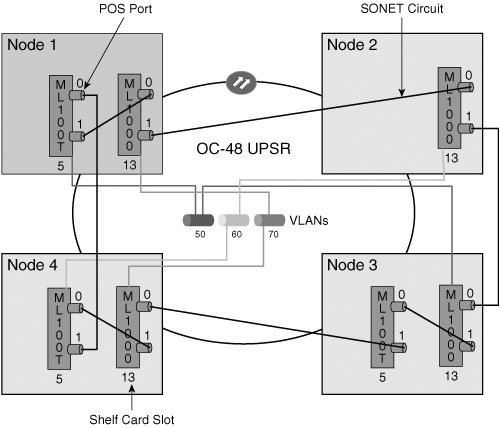
Each ML-Series card has two virtual Packet over SONET/SDH (POS) ports used to interconnect it to other Ethernet services interface cards (in the same or different ONS 15454 node), such as in a ring/RPR topology. These ports function similarly to OC-N card ports, and CTC is used to provision SONET/SDH circuits to these ports. The ML-Series cards can support contiguously concatenated (STS-1, STS-3c, STS-6c, STS-9c, STS-12c, STS-24c) and virtually concatenated (STS-1-2v, STS-3c-2v, STS-12c-2v) circuits. The ML-Series cards also support a software-based Link Capacity Adjustment Scheme (LCAS), which allows VCAT circuit group members to be added or removed from the circuit bandwidth in case of a failure or recovery from failure. Figure 6-12 shows an example of a four-node ONS 15454 MSPP ring equipped with seven total ML-Series cards being linked by SONET circuits over an OC-48 UPSR in an RPR configuration. Figure 6-12. RPR Application over ONS 15454 MSPP Using ML-Series Cards Example All ML-Series cards have an LED called ACT, which indicates the card's status, and an LED labeled FAIL, which remains illuminated if the card's processor is not ready or if a failure has occurred. Additionally, each card has a port LED, which is green to indicate a link and amber to indicate that the port is active. |

EAN: 2147483647
Pages: 140