Chapter 18: Going Wardriving
|
|
Making a Reflector
The easiest material for making such reflectors is galvanized soft iron hardware cloth with a 1/4' mesh, which can be had in rolls for a couple of dollars at any hardware store or home improvement center. You cut an 8" x 8" or 6" x 6" square with tinsnips, optionally cover the edges with duct tape to cover the sharp points, and then shape it into a parabola.
You can make a reflector like this from any soft metal that keeps its shape when bent. Galvanized iron sheet like that used in heating ducts works well, but it's not as easy to find in small quantities, not as easy to cut with tinsnips (especially dull tinsnips) and its cut edges are razor sharp. I also found when I bent a piece of galvanized iron sheet into a parabola, that over a few days' time it tended to flatten out and lose its shape. Hardware cloth is softer iron and keeps its shape better. Also, hardware cloth comes in a roll, and when you cut a piece it will already be curved to within striking distance of the shape you want.
On the next page is Figure 17.4, a full-size template for the parabola. The squares are 1/4'. Slap the page down on a copy machine and copy the page onto a sheet of paper. Cut your hardware cloth, tape the edges if you choose, and then shape the hardware cloth until its bottom edge follows the curve on the paper. That's literally all there is to it!
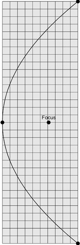
Figure 17.4: The Parabolic Curve Template.
The focus of a parabola of this curvature is just a hair over 1 1/2' forward from the center of the curve. For shaping the field of an access point the accuracy of the curve isn't a serious issue, though it should be within 1/8" or so for best results. Do the best you can, and getting close is almost as good as being bang-on.
How Parabolic Reflectors Work
It's useful to have an intuitive grasp of how parabolic reflectors work, especially once you have to adjust one. The geometry of a parabolic reflector brings parallel rays to a single point focus. It works the other way, too: Rays emitted from a single point that strike a parabolic reflector will be reflected in parallel in a single direction (see Figure 17.5).
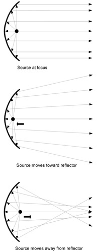
Figure 17.5: How Parabolic Reflectors Work.
Most of the times you'll use a parabolic reflector in Wi-Fi work will involve very high gain antennas that need to cross distances measured in miles rather than yards. For that kind of work, you want to create as tight a beam as possible. Placing the microwave source at the focus of the parabolic reflector will create a tight beam, with most of the microwave energy traveling in a single direction.
By moving the microwave source either toward the reflector or away from the reflector, you can make the beam broaden out (as in the center diagram) or converge on itself and then broaden out (as in the bottom diagram). The center and bottom diagrams are mostly equivalent in their effects, in that they create a much broader field sent in generally one direction.
It takes relatively little movement toward or away from the reflector to create a tremendous difference in the shape of the microwave field. Keep that in mind later on, when we discuss adjusting the mesh reflector-which actually involves adjusting the position of an access point's antenna relative to the reflector.
Mounting the Reflector
The mesh reflector concept is simple, and actually making one will probably take you half an hour at worst. The difficulties you'll have will lie in keeping the reflector from moving once you aim it. Aiming it is tricky, not so much in terms of steering the beam as in keeping the dead spots away from important places in your house. (More on aiming the reflector later.) Once you get it set correctly, you don't want a light breeze to knock it over.
I tried a number of different things, but what worked best was actually what I tried first: Attaching the reflector to a sheet of scrap acrylic plastic 8" x 11". That size isn't critical; it was just what came to hand in the scrap box. What you want is something big enough to comfortably hold both the reflector and the access point.
To size the base, put your reflector and curve template down on a piece of paper or cardboard and position your access point so that one of its antennas lies directly above the point marked 'Focus' on the template. Then choose a circle or rectangle of plastic or wood (but not metal!) that comfortably embraces the reflector and the access point. The smaller an access point it, the less the body of the device will get in the way. This is yet another reason why I like the D-Link DWL-900AP+: It's quite small and has only one antenna. Fading isn't much of a problem here, so giving up dual antennas (and thus diversity reception) was not a big loss. If you use a twoantenna AP, you will have to remove one antenna and then set the AP's configuration screen parameter that governs which antenna is used. You don't want your Wi-Fi signals going out to an empty antenna jack!
Figure 17.6 shows a 6" x 6" reflector resting on a paper copy of the curve template. The dark surface is a piece of 1/8" clear acrylic with its blue protective film still in place. I've omitted the access point so you can see how the curve of the reflector matches the curve on the template. As a general rule of thumb, the more of the printed parabola on the template that your reflector covers, the narrower and longer the field formed by the reflector will be. I made and tested an 8" x 8" reflector, but it did no better a job than the 6" x 6" reflector and made the entire assembly larger and more ungainly.
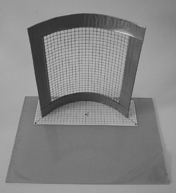
Figure 17.6: The Reflector on the Curve Template.
Once you have things arranged so that they will fit on the base you've chosen, tape the template securely to the base. Using a very small drill bit (1/32" or something near to that) drill pairs of holes on either side of the parabolic curve on the template. The holes will allow you to secure the mesh reflector to the base by threading short lengths of copper wire up through the holes and then twisting the ends together by gripping them with a needle-nose pliers. See the photo in Figure 17.7.
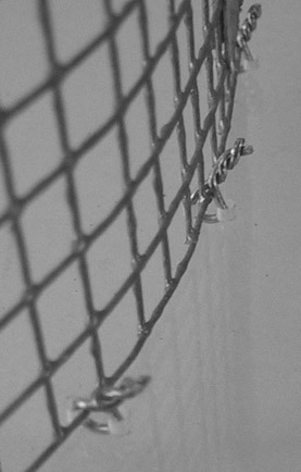
Figure 17.7: Tying Down the Mesh Reflector with Wire.
I suggest drilling a small hole through the dot marking the focus on the template, just so you don't lose track of where the focus falls when you take the paper pattern away.
You also need to take into account the CAT 5 data cable and power cable that connect into the back of the access point. One mistake I made in my first mesh reflector assembly was not allowing quite enough room for the cables. I eventually cut a largish hole in the plastic sheet and put four short legs on the assembly so that the CAT 5 cable could be routed below the plastic sheet. The cables eventually became the gnarliest single problem with the whole gadget. The final form of this particular version is shown in Figure 17.8.
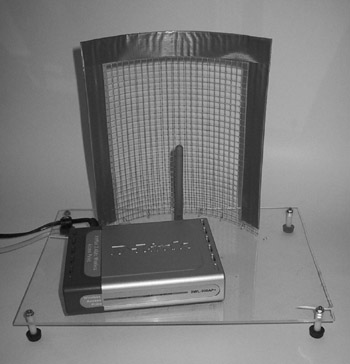
Figure 17.8: The Complete Reflector Assembly and Access Point.
As I'll explain shortly, one aspect of adjusting the reflector means adjusting the position of the access point in front of the reflector, and if you're not careful, tension on the cables will disturb the position of the access point and destroy your adjustment. Once you know what position the access point will need to be in, you can use cable clamps or tie-wraps to fix the cables to the base so that they do not pull on the access point and change its adjustment.
Mounting the Access Point
Attaching the access point itself to the reflector base might be a problem. My DLink and Cisco APs have bolt slots in their bases, to allow attaching them to walls. Many other APs do not have bolt slots, and in those cases you'll just have to get creative. You could try 3M Scotch Double-Sided Foam Mounting Tape but beware that this stuff is sticky enough that someday you'll have to scrape it off. You could also use Fun-Tak, which might work very well as well and is much easier to scrape off a surface. Both of these should be easily found at a local office supply store.
To give yourself the most precise control over the shape of the field formed by the mesh reflector, you need to be able to move the AP's antenna along a short line that runs from immediately behind the parabola's focus to immediately in front of the focus. (Look back to Figure 17.5 to see why.) Moving the antenna from side to side changes the direction of the field more than its shape, and you can do that by moving the assembly as a whole.
I found a pair of round-head brass 6-32 machine screws that fit snugly into the DWL-900AP+ bolt slots. See Figure 17.9 to get an idea of how the screws fit into the bolt slots. Round-head screws are best; the flatter head 'binder' screws will rattle around and come loose very easily. I then cut a pair of slots in the Plexiglas base allowing the AP to slide forward or back but not side to side. This is best done by drawing short lines with a permanent marker and then drilling a series of holes side by side, finally smoothing out the holes into slots with a small file. Make sure the slots run perpendicular to the mesh reflector and not at an angle. The idea is to be able to move the AP's antenna along a line running from behind the focus point to in front of it.
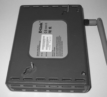
Figure 17.9: Machine Screws in the AP Bolt Slots.
After positioning the AP on the Plexiglas, put washers and hex nuts on the machine screws but leave yourself some slack to allow the AP to slide forward and back during adjustment. The initial position should put the antenna as close as possible to the reflector's focal point.
Adjusting the Mesh Reflector
Adjusting the Tin Can Bandwidth Expander is easy, because it's designed to work on the client side. You aim it while watching your signal strength change on a client application display like that of Netstumbler. With a mesh reflector behind your access point, you're still forced to monitor signal strength at the client end of a connection, but you're adjusting something that may be at the other end of your home or office. Having some help is useful-especially if you're within earshot. ('A little bit to the left!') If earshot fails (or if hollering across the length of your home or office is a non-starter) a pair of cell phones or Family Radio Service (FRS) walkietalkies is extremely useful.
In adjusting the mesh reflector, it's better to think of what you're doing as changing the shape of the field rather than creating some kind of beam. A 6" square of hardware cloth isn't big enough to create a very tight beam, and that's not necessarily what you want anyway. In my case, I wanted to change the shape of the access point's field from something roughly circular to something roughly elliptical, with the ellipse's long axis running down the diagonal dimension of my house.
I say 'roughly' with some emphasis. Radiation patterns from antennas are not simple circles or ellipses, but more significantly, the environment within which the antenna operates changes the shape of the pattern radically. The structure and materials of your home or office have a powerful effect on where the field will reach, and how well. For example, my kitchen and cupboard cast a microwave shadow on my living room. The original field pattern was roughly circular, with a huge 'dent' on one side of the circle. (Look back to Figure 17.1.) This dent was the reduction in field strength caused by the presence of the kitchen between my access point and my living room. The whole point in creating the mesh reflector was to fill in that dent as much as possible and improve my ability to connect to my access point from my living room coffee table.
There are actually two aspects to adjustment:
-
Adjusting the access point on the reflector's base. This is a relatively limited adjustment. You want to be able to slide the access point so that its vertical antenna moves on a straight line, perpendicular to the reflector, from a little behind to a little in front of the precise focal point. The full distance you want to allow for is 1/2' at most, and in practice it won't be much more than an eighth of an inch either way. Moving the access point from side to side with respect to the reflector gives you very little that moving the entire reflector assembly from side to side does not. This adjustment changes the shape of the microwave field, largely in terms of length and width.
-
Adjusting the entire assembly. This simply means moving the whole device around on the shelf or desk. This primarily changes the direction in which the field is pointed.
I played around with different ways to limit the movement of the AP on the reflector base, but the best one was machine screws in the bolt slots of the DWL-900AP+, moving within 1/2' slots drilled in the Plexiglas base. This adjustment, unfortunately, is highly dependent on the shape of your access point and what sort of mounting it uses. Without bolt slots it's very difficult to adjust the AP with respect to the focal point. If your AP does not have bolt slots, I recommend somehow fixing it in place at the reflector's focus and performing all your adjustments by moving the assembly as a whole.
Here's how you go about the adjustment.
-
Sketch out your house or office and print a few copies to draw on. I use Visio 2000, which has some very nice templates for architectural drawing. (All the technical figures in this book were drawn with Visio 2000.) Visio is a great product and I highly recommend it. If you're on a bit more of a budget you can also try Smart Draw which is a shareware product that's a bit less costly than Visio. Smart Draw is found at www.smartdraw.com.
-
Find out where your field reaches, and where your dead spots are, without using the reflector. This is a standard technique for installing Wi-Fi access points under any circumstances: Walk around with your Wi-Fi equipped laptop or PDA, watching a field strength indicator like the one in Netstumbler (see Chapter 18). Mark weak spots and dead spots on your architectural sketch. If you're really ambitious, choose a particular field strength value and mark a point on your plan anywhere the reading shows that value. If you mark enough of these points, you can draw what amounts to field isoclines on your sketch, and literally show yourself the shape of your field. It won't be a simple shape, and there may be holes like Swiss cheese in the middle of it.
-
Decide where the field must reach, and where it doesn't have to reach. Sure, it would be nice to be able to take your laptop anywhere in your home or office and connect at top speed. But unless you have a fairly small home or office, you will have weak spots, and in any substantial space with a lot of internal structure you will have dead spots. Unless you're prepared to install multiple access points with cables connecting them, some triage may be necessary.
-
Put the reflector in place, and see what you've got. Aim the reflector assembly in the direction where you need the longest reach for the access point's field. Repeat step 2, checking each location where you need coverage.
-
Tweak and try for optimal coverage. This is the hard part. If you find locations with weak signal off to the sides of the field, move the access point closer to the reflector to broaden the field. Keep the antenna on the reflector axis, otherwise the field will veer to one side or another. If the field is more than wide enough but not long enough, see if the access point antenna is at the focus. Only at the focus will the field be of maximum length. If the field appears to be pointed in the wrong direction, turn the entire assembly rather than attempt to move the access point with respect to the mesh reflector. Each time you change either the access point's position on the base or the entire assembly's position on its shelf or desk, you'll have to re-check the field to see if the AP's signal reaches where it must. Note that this can be a very touchy business. If you're impatient, well, it can drive you crazy!
-
Try to keep the assembly from moving once it's adjusted. This means keeping other objects away from it, and more than anything else keeping anything from yanking on the AP's CAT 5 and power cables. If you can somehow mark on the surface of the desk or shelf where the four feet of the assembly rest after adjustment is complete, you can get a head start on readjusting the device if you ever have to move it. Drawing light lines with a pencil around the four feet to mark their position works well, though be careful not to move the assembly in the process.
|
|
EAN: 2147483647
Pages: 181