AppendixA.Frame Relay Switch Configuration
Appendix A. Frame Relay Switch ConfigurationUnless you have a dedicated Frame Relay switch at your disposal, you will need to configure one of your routers to simulate a Frame Relay switch. NOTE Your chosen router can be one, that you use within the lab scenarios or a dedicated router such as a 4000 with sufficient serial interfaces for this task. Once configured appropriately, your router will provide the necessary mesh of permanent virtual circuits (PVCs) to meet the requirements stipulated in the lab scenarios. Figure A-1 shows connectivity from R1 to R4 with R5 acting as the Frame Relay switch. In this example, R5 connects to both R1 and R4 using X21 female data communications equipment (DCE) cables; these will provide a clock signal to the X21 male data terminal equipment (DTE) cables attached to R1 and R4. Figure A-1. Frame Relay Switch Physical Connectivity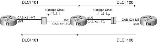 R5 will be configured to supply Data Link Control Identifier (DLCI) 101 on interface Serial 5/0 toward R1 and DLCI 100 on interface Serial 1/0 toward R4. It will send data from R1 PVC associated to DLCI 101 to DLCI 100 and data from R4 PVC associated to DLCI 100 to DLCI 101 by using Frame Relay routing commands. The final configuration will result in the logical connectivity as shown in Figure A-2. Figure A-2. Frame Relay Switch Logical Connectivity
Example A-1 shows the configuration for R5. Example A-1. R5 Frame Relay Switching Configurationframe-relay switching ! interface Serial1/0 no ip address encapsulation frame-relay no shutdown clockrate 128000 frame-relay intf-type dce frame-relay route 100 interface Serial5/0 101 ! interface Serial5/0 no ip address no shutdown encapsulation frame-relay clockrate 128000 frame-relay intf-type dce frame-relay route 101 interface Serial1/0 100 By default, the Frame Relay Local Management Interface (LMI), which is used for the signalling between the Frame Relay switch and router, will be set to cisco. You should experiment with the other settings of ansi and q933a; however, be aware that the router will attempt to auto negotiate this parameter. To verify your configuration, use the command show frame-relay pvc as demonstrated in Example A-2. The output displays DLCI status information, and a successful configuration will result in PVC status Active for each DLCI. Example A-2. show frame-relay pvc Command OutputR5#show frame-relay pvc PVC Statistics for interface Serial1/0 (Frame Relay DCE) DLCI = 100, DLCI USAGE = SWITCHED, PVC STATUS = ACTIVE, INTERFACE = Serial1/0 input pkts 0 output pkts 0 in bytes 0 out bytes 0 dropped pkts 6 in FECN pkts 0 in BECN pkts 0 out FECN pkts 0 out BECN pkts 0 in DE pkts 0 out DE pkts 0 out bcast pkts 0 out bcast bytes 0 pvc create time 09:25:16, last time pvc status changed 08:09:30 Num Pkts Switched 0 PVC Statistics for interface Serial5/0 (Frame Relay DCE) DLCI = 101, DLCI USAGE = SWITCHED, PVC STATUS = ACTIVE, INTERFACE = Serial5/0 input pkts 0 output pkts 0 in bytes 0 out bytes 0 dropped pkts 6 in FECN pkts 0 in BECN pkts 0 out FECN pkts 0 out BECN pkts 0 in DE pkts 0 out DE pkts 0 out bcast pkts 0 out bcast bytes 0 pvc create time 09:25:16, last time pvc status changed 08:15:03 Num Pkts Switched 0 You can also verify your Frame Relay routing configuration and ensure that each PVC is active in a more concise manner by issuing the command show frame-relay route as shown in Example A-3. Example A-3. show frame-relay route Command OutputR5#show frame-relay route Input Intf Input Dlci Output Intf Output Dlci Status Serial1/0 100 Serial5/0 101 active Serial5/0 101 Serial1/0 100 active |

EAN: 2147483647
Pages: 268