AppendixB.LS1010 ATM Switch Configuration
Appendix B. LS1010 ATM Switch ConfigurationThroughout the lab exercises, ATM connectivity was achieved by a back-to-back connection between two routers. This scenario limits configurations to permanent virtual circuits (PVCs) only; however, you should be familiar with a Cisco LightStream 1010 to provide both PVC and SVC configurations. The LightStream 1010 or LS1010 is a Cisco workgroup ATM switch that is used to connect power users and create departmental LANs within a single building or a small campus. You might also find a LS1010 in most of the practice labs that training companies offer. The following example shows the LS1010 configuration to have Router_A and Router_B to communicate using PVCs. Figure B-1 shows the physical connectivity from Router_A to Router_B with a LS1010 as the ATM switch. Figure B-1. LS1010 Physical Connectivity
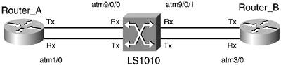
The LS1010 switch will provide the signaling to both routers to deliver data from PVC 100 coming from Router_A to PVC 100 toward Router_B and vice versa. The final configuration will result in the logical connectivity as shown in Figure B-2. Figure B-2. LS1010 Switch Logical Connectivity
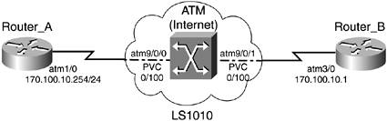
Example B-1 shows the configuration for LS1010 switch, Router_A, and Router_B. Example B-1. LS1010 Switch, Router_A, and Router_B ConfigurationRouter_A#show run interface atm1/0 Building configuration... Current configuration : 101 bytes ! interface ATM1/0 ip address 170.100.10.254 255.255.255.0 no ip address no atm ilmi-keepalive ! pvc 0/100 protocol ip 170.100.10.1 broadcast ! end ________________________________________________________________ Router_B#show run interface atm3/0 Building configuration... Current configuration : 140 bytes ! interface ATM3/0 ip address 170.100.10.1 255.255.255.0 no atm ilmi-keepalive ! pvc 0/100 protocol ip 170.100.10.254 broadcast ! end ! ________________________________________________________________ ! The Following is an alternative configuration on Router_B, in an older fashion, ! that works as well. You need to configure map-list and map-group commands ! in order to achieve the same result: Router_B#show run interface atm3/0 Building configuration... Current configuration : 140 bytes ! interface ATM3/0 ip address 170.100.10.1 255.255.255.0 map-group PVC atm pvc 1 0 101 aal5snap no atm ilmi-keepalive ! map-list PVC ip 170.100.10.254 atm-vc 1 broadcast ! end ________________________________________________________________ ls1010#show running-config Building configuration... Current configuration: ! version 12.0 ! hostname ls1010 ! enable password cisco ! interface ATM9/0/0 description Router_A-ATM1/0 no ip address no ip directed-broadcast logging event subif-link-status no atm ilmi-keepalive atm pvc 0 100 interface ATM9/0/1 0 100 ! interface ATM9/0/1 description Router_B-ATM3/0 no ip address no ip directed-broadcast logging event subif-link-status no atm ilmi-keepalive ! interface Ethernet13/0/0 shutdown ! ip classless ! line con 0 transport input none line aux 0 line vty 0 4 password cisco login ! end By default, the encapsulation on the routers is AAL5. The configuration for PVC is very simple on the LS1010 and, contrary to the configuration on a Frame Relay switch, you need only "map" the PVC in one interface, as you can see for interface ATM9/0/0 in Example B-1. To verify your configuration, use the command show atm pvc, which will display the active PVCs and status as demonstrated in Example B-2. Example B-2. show atm vc and show atm svc OutputRouter_A#show atm vc VCD / Peak Avg/Min Burst Interface Name VPI VCI Type Encaps SC Kbps Kbps Cells Sts 1/0 1 0 100 PVC SNAP UBR 155000_ UP Router_A# ________________________________________________________________ Router_B# Router_B#show atm vc VCD / Peak Avg/Min Burst Interface Name VPI VCI Type Encaps SC Kbps Kbps Cells Sts 3/0 1 0 100 PVC SNAP UBR 155000 UP Router_B# ________________________________________________________________ ls1010#show atm vc Interface VPI VCI Type X-Interface X-VPI X-VCI Encap Status ATM9/0/0 0 100 PVC ATM9/0/1 0 100 UP ATM9/0/1 0 100 PVC ATM9/0/0 0 100 UP ls1010# The following example shows the required configuration for an SVC environment. Figure B-3 shows the physical connectivity from Router_A to Router_B with a LS1010 as the ATM switch. Figure B-3. LS1010 Physical Connectivity
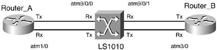
The LS1010 switch will provide the signaling to both routers and deliver data from Router_A toward Router_B and vice versa. The final configuration will result in the logical connectivity as shown in Figure B-4. Figure B-4. LS1010 Switch Logical Connectivity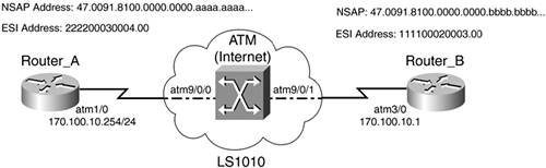 Example B-3 shows the configuration for the LS1010 switch, Router_A, and Router_B. Example B-3. LS1010 Switch, Router_A, and Router_B ConfigurationRouter_A#show run interface atm1/0 Building configuration... Current configuration : 293 bytes ! interface ATM1/0 ip address 170.100.10.254 255.255.255.0 no ip route-cache no ip mroute-cache atm esi-address 222200030004.00 no atm ilmi-keepalive pvc 0/5 qsaal ! pvc 0/16 ilmi ! ! svc nsap 47.0091810000000000BBBBBBBB.111100020003.00 protocol ip 170.100.10.1 broadcast ! end Router_A#show atm svc VCD / Peak Avg/Min Burst Interface Name VPI VCI Type Encaps SC Kbps Kbps Cells Sts 1/0 211 0 51 SVC SNAP UBR 155000 UP Router_A# Router_A#show atm vc VCD / Peak Avg/Min Burst Interface Name VPI VCI Type Encaps SC Kbps Kbps Cells Sts 1/0 1 0 5 PVC SAAL UBR 155000 UP 1/0 2 0 16 PVC ILMI UBR 155000 UP 1/0 211 0 51 SVC SNAP UBR 155000 UP Router_A# Router_A#ping 170.100.10.1 Type escape sequence to abort. Sending 5, 100-byte ICMP Echos to 170.100.10.1, timeout is 2 seconds: !!!!! Success rate is 100 percent (5/5), round-trip min/avg/max = 1/2/4 ms Router_A# ________________________________________________________________ Router_B#show run interface atm3/0 Building configuration... Current configuration : 171 bytes ! interface ATM3/0 ip address 170.100.10.1 255.255.255.0 map-group AAAA atm esi-address 111100020003.00 no atm ilmi-keepalive pvc 0/5 qsaal ! pvc 0/16 ilmi ! end ! ! map-list AAAA ip 170.100.10.254 atm-nsap 47.0091810000000000AAAAAAAA.222200030004.00 broadcast ! Router_B#show atm svc VCD / Peak Avg/Min Burst Interface Name VPI VCI Type Encaps SC Kbps Kbps Cells Sts 3/0 1011 0 36 SVC SNAP UBR 155000 UP Router_B#Router_B# Router_B#sh atm vc VCD / Peak Avg/Min Burst Interface Name VPI VCI Type Encaps SC Kbps Kbps Cells Sts 3/0 1 0 5 PVC SAAL UBR 155000 UP 3/0 2 0 16 PVC ILMI UBR 155000 UP 3/0 1011 0 36 SVC SNAP UBR 155000 UP Router_B# Router_B#ping 170.100.10.254 Type escape sequence to abort. Sending 5, 100-byte ICMP Echos to 170.100.10.254, timeout is 2 seconds: !!!!! Success rate is 100 percent (5/5), round-trip min/avg/max = 1/2/4 ms ________________________________________________________________ ls1010#show running-config Building configuration... Current configuration: ! interface ATM9/0/0 description Router_A no ip address no ip directed-broadcast logging event subif-link-status no atm ilmi-keepalive atm prefix 47.0091.8100.0000.0000.aaaa.aaaa... ! interface ATM9/0/1 description Router_B no ip address no ip directed-broadcast logging event subif-link-status no atm ilmi-keepalive atm prefix 47.0091.8100.0000.0000.bbbb.bbbb... end ls1010#show atm vc Interface VPI VCI Type X-Interface X-VPI X-VCI Encap Status ATM9/0/0 0 5 PVC ATM13/0/0 0 60 QSAAL UP ATM9/0/0 0 16 PVC ATM13/0/0 0 36 ILMI UP ATM9/0/0 0 36 SVC ATM9/0/1 0 51 UP ATM9/0/1 0 5 PVC ATM13/0/0 0 73 QSAAL UP ATM9/0/1 0 16 PVC ATM13/0/0 0 49 ILMI UP ATM9/0/1 0 51 SVC ATM9/0/0 0 36 UP Configuring SVCs is simple on the LS1010. Contrasted with PVCs, for SVCs the "map" is completed on the routers, not on the LS1010. An important thing to consider is that you need to configure the PVC 0/5 for ATM Adapter Layer (AAL) signaling and PVC 0/16 for Integrated Local Management Interface (ILMI). The ATM switch will use the Public-Network Node Interface (PNNI) protocol to route through the ATM network. Notice that two different techniques are used to configure the maps between Router_A and Router_B. On Router_A, the svc nsap command was configured to map the remote ATM Network Service Access Point (NSAP) address and the IP address. On Router_B, the map-list and map-group commands were configured to also map the remotely ATM NSAP and IP address. If you do not configure the atm prefix command within LS1010, it is still working, because the ILMI on the routers will learn the ATM Prefix address (NSAP) from the switch (LS1010) and add the End System Identifier (ESI) address or local address, to make up the entire NSAP address. You just need to use the show interface atm command on the routers to see the ATM address to use on the map or svc nsap commands. Example B-4 shows the output from a show interface atm command on Router_A to capture the ATM NSAP address. Example B-4. show interface on Router_ARouter_A#show interface atm 1/0 ATM1/0 is up, line protocol is up Hardware is TI1570 ATM Internet address is 170.100.10.254/24 MTU 4470 bytes, sub MTU 4470, BW 155520 Kbit, DLY 80 usec, reliability 255/255, txload 1/255, rxload 1/255 NSAP address: 47.0091810000000090B14C9C01.222200030004.00 Encapsulation ATM, loopback not set Encapsulation(s): AAL5, PVC mode 2047 maximum active VCs, 1024 VCs per VP, 3 current VCCs VC idle disconnect time: 300 seconds Signalling vc = 1, vpi = 0, vci = 5 UNI Version = 4.0, Link Side = user Last input 00:00:07, output 00:00:07, output hang never Last clearing of "show interface" counters never Input queue: 0/75/0/0 (size/max/drops/flushes); Total output drops: 0 Queueing strategy: fifo Output queue: 0/40 (size/max) 5 minute input rate 0 bits/sec, 0 packets/sec 5 minute output rate 0 bits/sec, 0 packets/sec 19136 packets input, 238100 bytes, 0 no buffer Received 0 broadcasts, 0 runts, 0 giants, 0 throttles 0 input errors, 0 CRC, 0 frame, 1 overrun, 0 ignored, 0 abort 19299 packets output, 245785 bytes, 0 underruns 7 output errors, 0 collisions, 3 interface resets 0 output buffer failures, 0 output buffers swapped out Router_A# |
EAN: 2147483647
Pages: 268