Configuring Integrated IS-IS
| Integrated IS-IS is unique among the IP routing protocols covered in this book for a couple of reasons. First, it is the only protocol that must be enabled both as a process and on individual interfaces. Second, it is the only IP routing protocol that was not originally designed for IP. Because Integrated IS-IS uses CLNS PDUs rather than IP packets, the configuration is not always as obvious as that of the other protocols. An interesting side effect of the fact that Integrated IS-IS is a CLNS protocol is that the IP addresses of neighboring routers have no influence on the formation of adjacencies. As a result, IS-IS does not have the adjacency restrictions concerning secondary IP addresses that OSPF has. However, another result is that two interfaces with IP addresses from completely different subnets can become adjacent. IP will not work in such a situation, but the fact that the adjacency makes the link only "half broken" can cause some troubleshooting confusion. Case Study: A Basic Integrated IS-IS ConfigurationA basic Integrated IS-IS process is configured on a Cisco router in four steps:
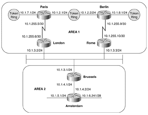
Figure 10.41 shows a small six-router internetwork divided into two areas. In the NETs, areas 1 and 2 will be encoded as 00.0001 and 00.0002, respectively, and the System IDs will be the MAC identifiers of the E0 or TO0 interfaces of each router. Table 10.4 shows the NETs encoded with this information. Figure 10.41. Area 1 is encoded as 00.0001 in the NET, and area 2 is encoded as 00.0002. The System ID of each NET is the E0 or TO0 MAC identifier. Table 10.4. The NETs used for the IS-IS configurations of the routers in Figure 10.41.
The configurations of Paris, London, Brussels, and Amsterdam are: Paris
London
Brussels
Amsterdam
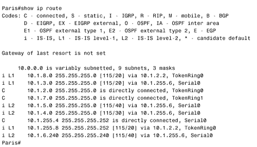
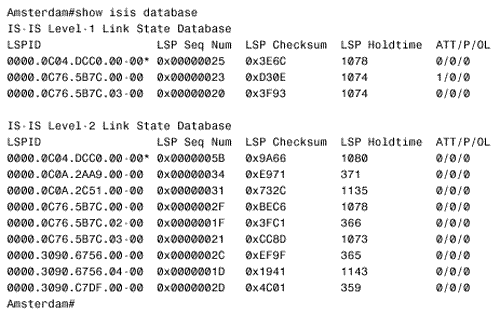
The configurations of Berlin and Rome are similar. A detail that you should notice is that CLNS routing is enabled in these configurations. The CLNS routing is necessary to handle the CLNS PDUs used by IS-IS. However, the clns routing command was not entered as a configuration step. Rather, the router entered it automatically when IS-IS was enabled. Figure 10.42 shows Paris' route table. Notice that the table contains both L1 and L2 routes. By default, Cisco routers are L1/L2 routers. This fact is also apparent by observing the routers' IS neighbor tables, as in Figure 10.43. Figure 10.42. Paris' route table shows both L1 and L2 routes, indicating that this router is an L1/L2 router. Figure 10.43. Berlin's IS neighbor table shows that both Paris and Rome are L1/L2 routers. Because every router in the internetwork of Figure 10.41 is an L1/L2, every router has formed both an L1 adjacency and an L2 adjacency. Consequently, every router has both an L1 and an L2 LS database. For example, Figure 10.44 shows the LS databases of Amsterdam. The L1 database contains an LSP originated by Amsterdam (0000.0c04.dcc0.00-00) [20] and an LSP originated by Brussels (0000.0c76.5b7c.00-00). It also contains a pseudonode LSP (0000.0c76.5b7c.03-00) originated by Brussels, representing the Ethernet link between Brussels and Amsterdam. Remember that the LSP ID is recognizable as that of a pseudonode LSP because the next -to-last octet, the Pseudonode ID, is non-zero .
Figure 10.44. Amsterdam has both a level 1 LS database and a level 2 LS database, indicating that the router is an L1/L2 router. The three LSPs indicate that Amsterdam's only L1 adjacency is with Brussels. This single adjacency is expected because Brussels is the only other router in area 2. Comparing Amsterdam's L2 database with the System IDs in Table 10.4 reveals that Amsterdam has an L2 adjacency with every router in the IS-IS domain, which is also expected because every router is an L1/L2. Case Study: Changing the Router TypesIn a small internetwork like the one in Figure 10.41, leaving all routers at their default type is acceptable. As the internetwork grows, these defaults become less and less acceptable. Not only is the processing and maintenance of two LS databases a burden on the router's CPU and memory, the L1 and L2 IS-IS PDUs being originated by every router become a burden on the buffers and bandwidth. Paris, Berlin, and Amsterdam in Figure 10.41 can be configured as L1 routers, because they have no direct connection to another area. To change the default router type, use the command is-type . For example, to make Berlin an L1 router its configuration is:
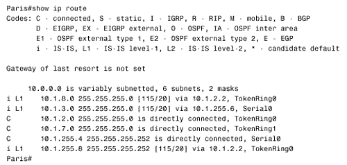
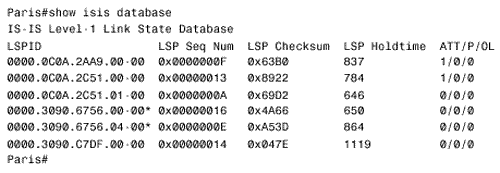
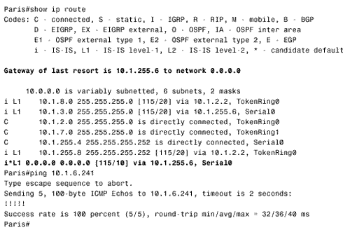
Paris and Amsterdam are configured similarly. Comparing Paris' route table in Figure 10.45 with its route table in Figure 10.42 shows that the L2 routes have been deleted. Similarly, comparing Figure 10.46 with Figure 10.44 shows that Amsterdam now has only an L1 LS database. Figure 10.45. After Paris is configured as an L1 router, its route table contains routes only to destinations within its own area. Figure 10.46. After Amsterdam is configured as an L1 router, it has only a level 1 link state database. With the L1 configurations shown so far, IP routing is not completely functional. Recall from the earlier discussion of the ATT bit in the LSPs that an L1/L2 router uses the ATT bit to tell L1 routers that it has an inter-area connection. Figure 10.47 shows that both London's LSP (0000.0c0a.2c51.00-00) and Rome's LSP (0000.0c0aA.2aa9.00-00) have ATT = 1. So Paris should know to send inter-area traffic to either London or Rome. In other words, Paris should have a default route to London or Rome, with London being preferred because it is metrically closer. Unfortunately, Figure 10.45 shows that there is no default route (0.0.0.0) in Paris' route table. Figure 10.47. The L1 LSPs of London and Rome have ATT = 1, indicating a connection to another area. The problem is that the ATT bit is a CLNS function, and the IP process cannot directly interpret the bit. There are two solutions to the problem. The first solution is to enable IS-IS for CLNS on the interfaces in addition to IS-IS for IP. For example, the serial interface configurations for London and Paris are: London
Paris
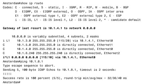
Figure 10.48 shows that Paris now has a default IP route pointing to London and that a ping to an inter-area destination is successful. Figure 10.48. After London and Paris have been configured as dual CLNP/IP routers, Paris understands the ATT bit and adds a default route to its route table. This first solution works in a dual CLNP/IP environment, but if IS-IS is being used as an IP-only routing protocol, enabling CLNS routing just for default IP routes may be undesirable. A second solution to the default route problem is to configure a static default route on the L1/L2 router and configure IS-IS to advertise the default with the command default-information originate . Using this method in area 2 of Figure 10.41, the Brussels' configuration is:
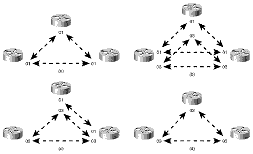
Figure 10.49 shows Amsterdam's route table with the default route that has been advertised by Brussels and a successful ping to an inter-area destination. Default routes and the default-information originate command are discussed in more detail in Chapter 12, "Default Routes and On-Demand Routing." Figure 10.49. Amsterdam's route table contains the default route statically configured at Brussels. Case Study: An Area MigrationTo change area addresses in an OSPF domain, downtime must be scheduled. However, IS-IS is designed to allow areas to be changed nondisruptively. As discussed in "Operation of Integrated IS-IS," Cisco routers can be configured with up to three area addresses. For two routers to form an L1 adjacency, they must have at least one area address in common. With multiple area addresses allowed, a new adjacency can take over while an old adjacency is being broken. This approach is useful when areas are being consolidated or split, when an area is being renumbered, or when area addresses assigned by multiple addressing authorities are being used in the same IS-IS domain. For example, the routers in Figure 10.50(a) all have an area address of 01. (A NET of one of these routers would look like 01.0000.0c12.3456.00.) In Figure 10.50(b), the routers have been assigned an additional area address of 03. Although multiple adjacencies are not actually formed, the routers do recognize that they have multiple area addresses in common. In Figure 10.50(c), area 01 has been removed from one of the routers. All three routers remain adjacent, because they all have at least one area address in common. Finally, in Figure 10.50(d), all of the 01 area addresses have been removed and the routers are all in area 03. At no time during the area migration was an adjacency lost. Figure 10.50. The support of multiple area addresses per router eases area changes. Suppose that the "powers that be" over the internetwork in Figure 10.41 decree that the area addressing scheme being used is inappropriate and should become GOSIP compliant. After registering with the U.S. GSA, the following components are to be used to construct the NETs: The new NETs are shown in Table 10.5.
Table 10.5. The new GOSIP-format NETs to be assigned to the routers in Figure 10.41.
The first step in changing the area addresses is to add the new NETs to the routers without changing the old NETs. Rome's IS-IS configuration is:
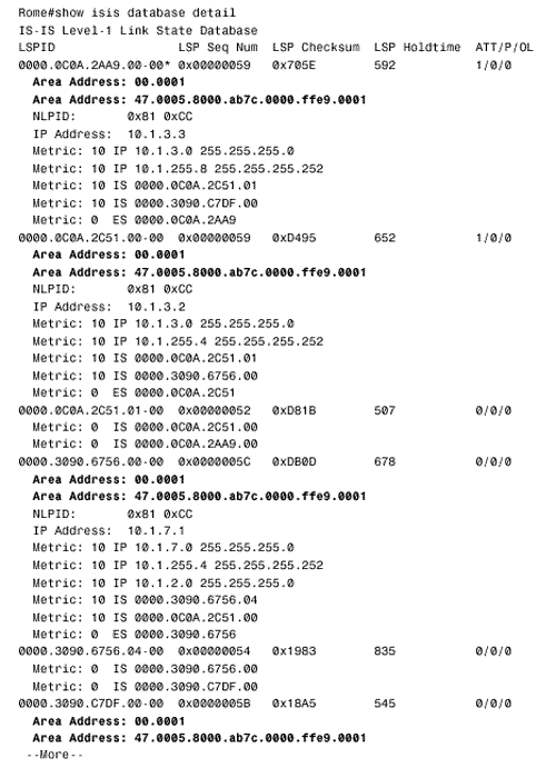
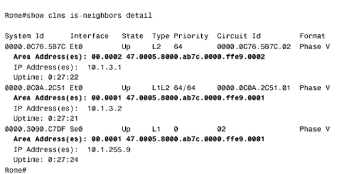
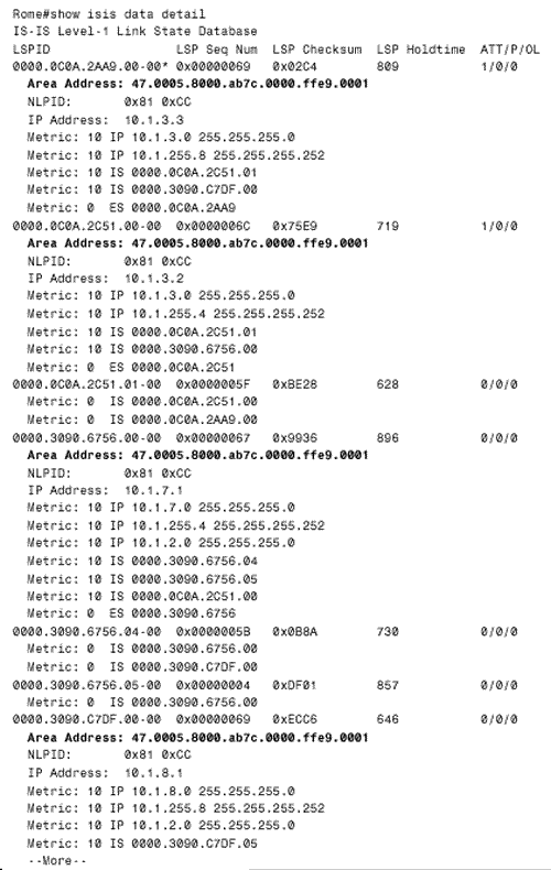
The other five routers are configured similarly. The results can be observed by using the detail keyword with either the show isis database command (Figure 10.51) or the show clns is-neighbors command (Figure 10.52). In both databases, multiple areas are associated with each router in the internetwork. Figure 10.51. The LSPs in Rome's link state database show that all routers in the internetwork of Figure 10.41 are advertising two area addresses. Figure 10.52. Rome's IS-IS neighbor table also shows multiple addresses associated with each neighbor. The last step of the migration is to delete the old NET statements from all routers. For example, under Rome's IS-IS configuration the command no net 00.0001.0000.0c0a.2aa9.00 is entered. Figure 10.53 shows some of the LSPs in Rome's database after the old NET statements have been removed from the routers. Figure 10.53. The LSPs in Rome's database show only a single area address. Case Study: Route SummarizationRoute summarization between areas in a link state protocol is introduced in Chapter 9. A more complete discussion of summarization, in the context of default routes, is presented in Chapter 12. Briefly, summary routes are useful because:
The primary disadvantages of summary routes are:
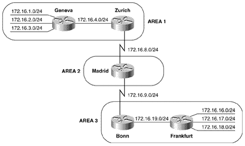
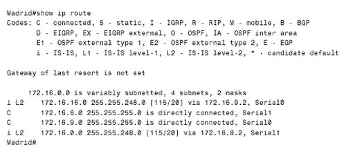
Summarization is enabled under the IS-IS configuration with the summary-address command. Any more-specific destination addresses that fall within the summarization range are suppressed, and the metric of the summary route is the smallest metric of all the more-specific addresses. Figure 10.54 shows an IS-IS internetwork with three areas. The addresses within area 1 can be summarized with 172.16.0.0/21, and the addresses within area 3 can be summarized with 172.16.16.0/21. The configurations of Zurich, Madrid, and Bonn are [21] :
Zurich
Madrid
Bonn
Figure 10.54. Zurich and Bonn are summarizing areas 1 and 3 into area 2. Notice that Madrid, which has no L1 neighbors, is configured as an L2 router. Zurich and Bonn are summarizing their areas into the level 2 backbone. The results of the summarization can be seen in Madrid's route table (Figure 10.55). Figure 10.55. Madrid's route table shows the summary addresses advertised by Bonn and Zurich. Case Study: AuthenticationIS-IS authentication is limited to cleartext passwords only. This mode of authentication provides weak security against a determined attack on the internetwork but is effective for preventing service disruptions from misconfigured or unauthorized routers. Cisco IOS supports IS-IS authentication on three levels: between neighbors, area wide, and domain wide. The three authentication levels can be used by themselves or together. The rules for IS-IS authentication are:
To authenticate between neighbors, the isis password command is used to configure a password on the connected interfaces. The command specifies a password and specifies whether the password is for L1 or L2 adjacencies. Passwords for either or both levels can be specified on an interface, and the passwords for each level can be the same or different passwords. When configured, the passwords are carried in authentication information CLVs in the L1 or L2 Hellos between IS-IS neighbors. For example, to authenticate between Geneva, Zurich, and Madrid in Figure 10.54, the configurations are: Geneva
Zurich
Madrid
Since the adjacency between Geneva and Zurich is L1, only a level 1 password (Alps) is specified. Between Zurich and Madrid, only an L2 adjacency exists, so a level 2 password (Pyranees) is used. Note that if no level-1 or level-2 keyword is specified, the isis password command defaults to level 1. To authenticate within an area, the area-password command is used to specify a password under the IS-IS configuration. Whereas the password specified by the isis password command is carried in Hellos, the password specified by the area-password command is carried in all L1 LSPs, CSNPs, and PSNPs. So the neighbor-level password regulates the establishment of adjacencies, and the area-level password regulates the exchange of level 1 link state information. If area authentication is not configured correctly, routers will still become adjacent but L1 LSPs will not be exchanged. To configure area passwords in area 3 of Figure 10.54, the configurations of Bonn and Frankfurt are: Bonn
Frankfurt
To authenticate domain wide, the domain-password command is used. The password specified by this command is carried in L2 LSPs, CSNPs, and PSNPs. As a result, domain authentication regulates the exchange of level 2 route information. Like area authentication, domain authentication does not authenticate L2 adjacencies, but does authenticate the exchange of L2 LSPs. To configure domain authentication in the internetwork of Figure 10.54, only Zurich, Madrid, and Bonn must be configured because Geneva and Frankfurt are L1 routers. The configurations are: Zurich
Madrid
Bonn
|
