Troubleshooting Integrated IS-IS
| The basic methods for troubleshooting IS-IS are very similar to the methods for troubleshooting OSPF, as discussed in Chapter 9. A major aspect of troubleshooting Integrated IS-IS that is different from the other IP routing protocols is that IS-IS uses CLNS PDUs rather than IP packets. If you are troubleshooting the protocol itself, remember that you are troubleshooting CLNS, not IP. As with all routing protocols, the first troubleshooting step is to check the route table for accurate information. If an expected route entry is missing or incorrect, the remainder of the troubleshooting task is to determine the source of the problem. After the routing table, the link state database is the most important source of troubleshooting information. As recommended in Chapter 9, it is good practice to keep a copy of the L1 link state database for every area, and a copy of the L2 link state database. These stored copies of the databases should be updated regularly, as part of your routine baselining procedures. When things go wrong, these stored databases provide a steady-state reference. When examining an individual router's configuration, consider the following:
Troubleshooting IS-IS AdjacenciesThe command show clns is-neighbors displays the IS-IS neighbor table. The entire table is displayed by default, or you can specify a particular interface. From this table, you can observe whether all expected neighbors are present and whether they are the correct type. For more information, such as the area addresses and IP addresses associated with each neighbor and the uptime of each neighbor, use the show clns is-neighbors detail command. When examining adjacencies, consider the following:
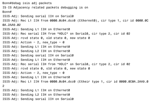
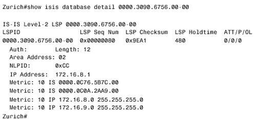
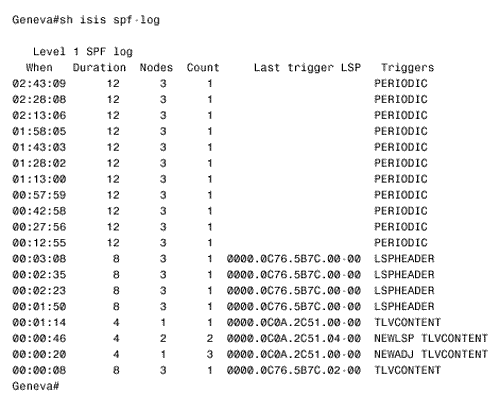
Figure 10.56. The details of IS-IS Hellos (IIHs) can be observed with the debug isis adj-packets command. This display is from router Bonn in Figure 10.54. Troubleshooting the IS-IS Link State DatabaseThe IS-IS link state database is examined with the command show isis database . If the router is an L1/L2, both of the databases are displayed by default. To observe only one of the databases, use the level-1 or level-2 keywords. To examine the LSPs in more detail, use the detail keyword. A single LSP can be observed by specifying its LSPID, as in Figure 10.57. Figure 10.57. This LSP is from the L2 database of router Zurich in Figure 10.54. A sequence number that is noticeably higher than the sequence numbers of other LSPs might indicate instability either within the area or on the level 2 backbone. Another hint of instability is an LSP Holdtime that never gets very small. If instability is suspected, use the command show isis spf-log to list all SPF calculations recently performed by the router. In Figure 10.58, the SPF log for router Geneva in Figure 10.54 is shown. Nothing but the periodic SPF calculations triggered by the 15-minute database refreshes are shown until approximately three minutes before the log was displayed. At that time, frequent SPF calculations began occurring, indicating frequent changes of some sort in the internetwork. [22]
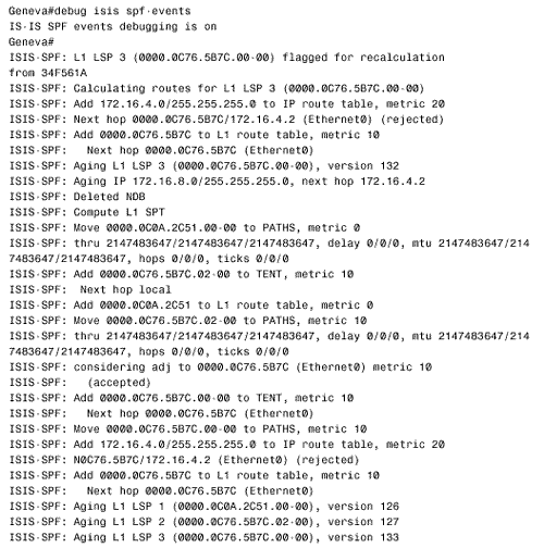
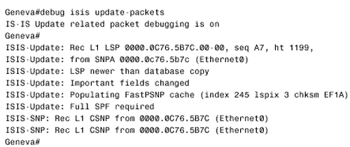
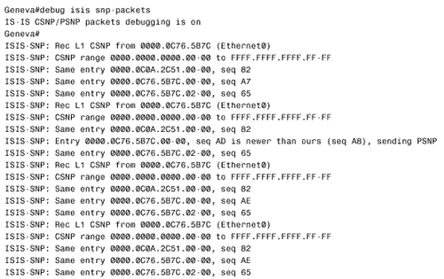
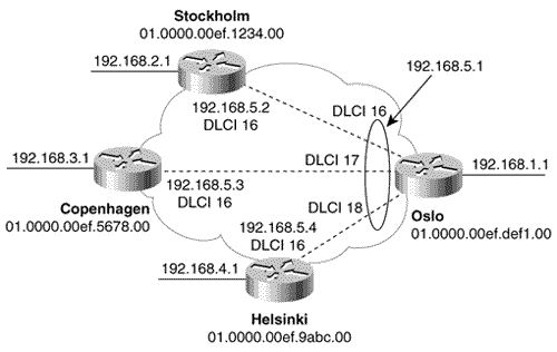
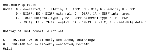
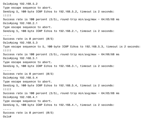
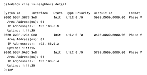
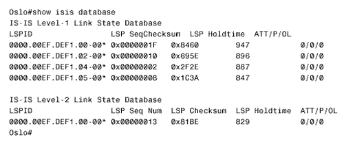
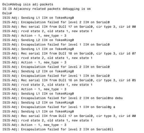
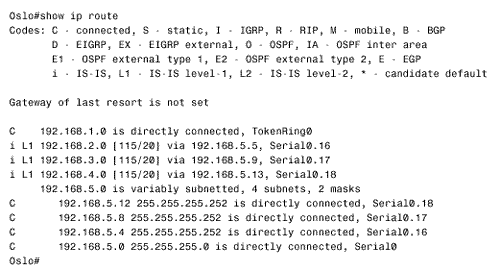
Figure 10.58. This SPF log reveals instability in area 1 of Figure 10.54.. To further investigate instabilities revealed by the SPF log, three useful debug commands are available. Figures 10.59, 10.60, and 10.61 show output from these three debug functions. In each case, the debug messages show the results of disconnecting and reconnecting the serial interface of Zurich in Figure 10.54 from the perspective of Geneva. The first, debug isis spf-triggers (Figure 10.59), displays messages pertaining to events that trigger an SPF calculation. The second command is debug isis spf-events (Figure 10.60). This command displays a detailed account of the SPF calculations caused by a triggering event. The third command, debug isis spf-statistics (Figure 10.61), displays information about the SPF calculation itself. Of particular interest is the time taken to complete the calculation, which can reveal performance problems on the router. Figure 10.59. debug isis spf-triggers displays messages about events that trigger an SPF calculation.. Figure 10.60. debug isis spf-events displays the details of an SPF calculation. Figure 10.61. debug isis spf-statistics displays statistical information about the SPF calculation.. Within each area, every router must have an identical link state database. Additionally, every L1/L2 and L2 router in the IS-IS domain must have an identical L2 database. If you suspect that a router's link state database is not correctly synchronized, examine the LSP IDs and the checksums. The same LSP IDs should exist in every database, and the checksum of each LSP should be identical in every database. Two debug commands can help you observe the synchronization process. The first is debug isis update-packets (Figure 10.62), which displays information about SNPs and LSPs the router sends and receives. The second command, debug isis snp-packets (Figure 10.63), displays information specific to the CSNPs and PSNPs the router sends and receives. Figure 10.62. debug isis update-packets displays information about SNPs and LSPs. Figure 10.63. debug isis snp-packets displays detailed information about CSNPs and PSNPs. Case Study: Integrated IS-IS on NBMA NetworksFigure 10.64 shows four routers running IS-IS connected by a partially meshed Frame Relay network. The IP addresses, DLCIs, and NETs are shown. The IS-IS configurations of all routers have been verified as correct, and no authentication is configured. Figure 10.64. IS-IS is not establishing adjacencies across the Frame Relay network. The problem with this internetwork is that no routes are being discovered (Figure 10.65). The IP addresses of neighbors' Frame Relay interfaces can be pinged, but the addresses of the routers' other interfaces cannot be pinged (Figure 10.66). The pings show that the Frame Relay PVCs are operational and that IP is working, but that the routers are not routing. Figure 10.65. The route table of Oslo in Figure 10.64 does not contain any IS-IS routes. Figure 10.66. Pings are successful to other interfaces connected to the Frame Relay network, but addresses reachable through the routers cannot be pinged. The next step is to check the IS-IS neighbor table. Oslo's neighbor table shows that Hellos have been received (Figure 10.67) and that the router knows the System IDs of its neighbors. It also shows that the IP addresses and the area addresses of the neighbors are correct. However, the state of all of the neighbors is Init , indicating that a full adjacency has not been established. A look at the link state database verifies the absence of adjacencies; the only LSPs in Oslo's database are the router's own LSPs (Figure 10.68). Figure 10.67. Oslo's IS-IS neighbor table shows that Hellos are being received but that the adjacency is not complete. Figure 10.68. Oslo's link state database does not contain any LSPs from any of its neighbors. The fact that Hellos are being received, but adjacencies are not being established, points to a problem with the Hellos themselves . If the parameters in the Hellos are not correct, the PDU is dropped. So debug isis adj-packets is enabled to observe the Hellos. Of particular interest in the debug output (Figure 10.69) are the "encapsulation failed" messages. These messages show that the router apparently cannot interpret the received Hellos and is dropping them. Figure 10.69. The results of enabling debug isis adj-packets show that Hellos are being dropped because of encapsulation failures. Any time an encapsulation failed message is received, suspicion should fall on the data link and its connected interfaces. Examining the interfaces with the show interface serial command reveals no significant error rates, so it is unlikely that the Hellos are being corrupted on the Frame Relay PVCs. The next step is to examine the interface configurations. The interface configurations for the four routers in Figure 10.64 are: Oslo
Stockholm
Copenhagen
Helsinki
A comparison of these configurations reveals the problem, although it may not be readily apparent. Stockholm, Copenhagen, and Helsinki are all configured with point-to-point subinterfaces. Oslo is not using subinterfaces. By default, a Cisco serial interface with Frame Relay encapsulation is a multi-point interface. Therefore, Stockholm, Copenhagen, and Helsinki are sending point-to-point IS-IS Hellos, and Oslo is sending L1 and L2 IS-IS LAN Hellos. IS-IS does not have a configuration option similar to OSPF's ip ospf network command; therefore, Oslo must be reconfigured with point-to-point subinterfaces, and the IP addresses must be changed so that each PVC is a different subnet (Figure 10.70). Figure 10.70. After Oslo has been configured with point-to-point subinterfaces and the PVCs have been readdressed as individual subnets, IS-IS routing is functioning. |
