Configuring RIPv2
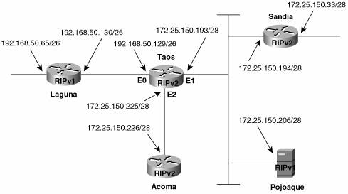
| Because RIPv2 is merely an enhancement of RIPv1 and not a separate protocol, the commands introduced in Chapter 5, "Routing Information Protocol (RIP)," for manipulating timers and metrics, and for configuring unicast updates or no updates at all, are used in exactly the same way. After a brief look at configuring a RIPv2 process, the rest of this section concentrates on configuring the new extensions. Case Study: A Basic RIPv2 ConfigurationBy default, a RIP process configured on a Cisco router sends only RIPv1 messages but listens to both RIPv1 and RIPv2. This default is changed with the version command, as in Example 6-1. Example 6-1. The version 2 command causes RIP to send and listen to RIPv2 messages only.router rip version 2 network 172.25.0.0 network 192.168.50.0 In this mode, the router sends and receives only RIPv2 messages. Likewise, the router can be configured to send and receive only RIPv1 messages, as in Example 6-2. Example 6-2. The version 1 command causes RIP to send and listen to RIPv1 messages only.router rip version 1 network 172.25.0.0 network 192.168.50.0 The default behavior can be restored by entering the command no version in config-router mode. Case Study: Compatibility with RIPv1The interface-level "compatibility switches" recommended by RFC 2453 are implemented in Cisco IOS with the commands ip rip send version and ip rip receive version. The network in Figure 6-12 contains routers speaking both RIPv1 and RIPv2. Additionally, Pojoaque is a Linux host running routed, which understands only RIPv1. The configuration of Taos is displayed in Example 6-3. Figure 6-12. Taos is running RIPv2 but must also speak Version 1 to some devices. Example 6-3. Taos's configuration.interface Ethernet0 ip address 192.168.50.129 255.255.255.192 ip rip send version 1 ip rip receive version 1 ! interface Ethernet1 ip address 172.25.150.193 255.255.255.240 ip rip send version 1 2 ! interface Ethernet2 ip address 172.25.150.225 255.255.255.240 ! router rip version 2 network 172.25.0.0 network 192.168.50.0 Because router Laguna is a RIPv1 speaker, E0 of Taos is configured to send and receive RIPv1 updates. E1 is configured to send both Version 1 and 2 updates, to accommodate the RIPv1 at Pojoaque and the RIPv2 at Sandia. E2 has no special configuration; it sends and receives Version 2 by default. In Example 6-4, debug ip rip is used to observe the messages sent and received by Taos. There are several points of interest here. First, notice the difference between the traps for RIPv1 and RIPv2 messages. The address mask and the Next Hop and Route Tag fields (both set to all zeros, in this case) of the RIPv2 updates can be observed. Second, it can be observed that interface E1 is broadcasting RIPv1 updates and multicasting RIPv2 updates. Third, because Taos has not been configured to receive RIPv1, the updates from Pojoaque (172.25.150.206) are being ignored. (Pojoaque has been misconfigured and is broadcasting its routing table.)[9]
Example 6-4. Using debugging, the RIP versions sent and received by Taos can be observed.Taos#debug ip rip RIP protocol debugging is on Taos# RIP: received v2 update from 172.25.150.194 on Ethernet1 172.25.150.32/28 - 0.0.0.0 in 1 hops RIP: ignored v1 packet from 172.25.150.206 (illegal version) RIP: sending v1 update to 255.255.255.255 via Ethernet0 (192.168.50.129) network 172.25.0.0, metric 1 RIP: sending v1 update to 255.255.255.255 via Ethernet1 (172.25.150.193) subnet 172.25.150.224, metric 1 network 192.168.50.0, metric 1 RIP: sending v2 update to 224.0.0.9 via Ethernet1 (172.25.150.193) 172.25.150.224/28 - 0.0.0.0, metric 1, tag 0 192.168.50.0/24 - 0.0.0.0, metric 1, tag 0 RIP: sending v2 update to 224.0.0.9 via Ethernet2 (172.25.150.225) 172.25.150.32/28 - 0.0.0.0, metric 2, tag 0 172.25.150.192/28 - 0.0.0.0, metric 1, tag 0 192.168.50.0/24 - 0.0.0.0, metric 1, tag 0 RIP: received v1 update from 192.168.50.130 on Ethernet0 192.168.50.64 in 1 hops RIP: received v2 update from 172.25.150.194 on Ethernet1 172.25.150.32/28 - 0.0.0.0 in 1 hopsPerhaps the most important observation to be made from Example 6-4 concerns the update being broadcast to Pojoaque: It does not include subnet 172.25.150.32. Taos knows this subnet, having learned it via multicast RIPv2 updates from Sandia. But Pojoaque cannot receive those multicasts because it speaks only RIPv1. Moreover, although Taos knows the subnet, the split horizon rule prevents Taos from advertising it out the same interface on which it was learned. So, Pojoaque does not know about subnet 172.25.150.32. Two remedies are available: First, Sandia could be configured to send both RIP versions. Second, split horizon can be turned off at Taos's E1 interface with the configuration in Example 6-5. Example 6-5. Split horizon is turned off here, in Taos's configuration.interface Ethernet1 ip address 172.25.150.193 255.255.255.240 ip rip send version 1 2 no ip split-horizon Example 6-6 shows the results. Taos is now including subnet 172.25.150.32 in its updates. Some forethought must be given to the possible consequences of disabling split horizon; Taos is now not only advertising 172.25.150.32 to Pojoaque but also advertising it back to Sandia. Example 6-6. With split horizon disabled on E1, Taos now includes subnet 172.25.150.32 in its updates to Pojoaque.Taos#debug ip rip RIP protocol debugging is on Taos# RIP: ignored v1 packet from 172.25.150.206 (illegal version) RIP: received v2 update from 172.25.150.194 on Ethernet1 172.25.150.32/28 -> 0.0.0.0 in 1 hops RIP: sending v1 update to 255.255.255.255 via Ethernet0 (192.168.50.129) network 172.25.0.0, metric 1 RIP: sending v1 update to 255.255.255.255 via Ethernet1 (172.25.150.193) subnet 172.25.150.32, metric 2 subnet 172.25.150.224, metric 1 subnet 172.25.150.192, metric 1 network 192.168.50.0, metric 1 RIP: sending v2 update to 224.0.0.9 via Ethernet1 (172.25.150.193) 172.25.150.32/28 -> 172.25.150.194, metric 2, tag 0 172.25.150.224/28 -> 0.0.0.0, metric 1, tag 0 172.25.150.192/28 -> 0.0.0.0, metric 1, tag 0 192.168.50.0/24 -> 0.0.0.0, metric 1, tag 0Case Study: Using VLSMReferring again to Figure 6-12, the subnet 172.25.150.0/24 has been assigned to the Internet shown. That subnet has been further subnetted to fit the various data links by expanding the mask to 28 bits; the available sub-subnets, in binary and dotted decimal, are shown in Table 6-2. Each of the subnets[10] will have, according to the 2n 2 formula, 14 host addresses. Out of these, 172.25.150.32, 172.25.150.192, and 172.25.150.224 have been used.
In Figure 6-13, a new Ethernet segment, Ethernet 3, has been added to Taos, with 60 hosts. A subnet with at least six host bits is required to accommodate this data link. A classful routing protocol would require that five of the subnets from Table 6-2 be assigned to Ethernet 3 [5 x (24 2) = 70], using secondary addresses. With classless protocols and VLSM, four of the subnets from Table 6-2 can be combined into a single subnet with a 26-bit mask. This step will provide six host bits (62 host addresses), and no secondary addressing is necessary. Four subnets, 172.25.150.64/28 to 172.25.150.112/28, are combined under one 26-bit mask: 172.25.150.64/26. Notice that the four subnets are not selected at random; the first 26 masked bits are identical and are unique within the group of 16 subnets.[11]
Figure 6-13. VLSM can be used to adapt addresses to the requirements of individual data links.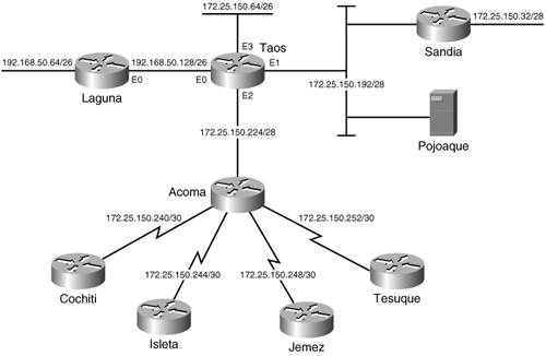 Also, in Figure 6-13, four serial links and four routers have been added to the network. Without VLSM, four of the subnets from Table 6-2 would have to be used for the four serial links. With VLSM, a single subnet from Table 6-2 can be used for all four serial links. 172.25.150.240 is selected, and a 30-bit mask is used to create the subnets in Table 6-3. Each of the resulting four subnets contains two host addresses.
The fundamental objective of subnetting is always the same: A router must be able to identify every data link with a unique address, distinct from any other address in the network. That is the common goal in the preceding two examples. In the first example, multiple addresses were combined into a single address by reducing the size of the mask until only the bits common to all of the addresses remain. Note that this result also happens when subnets are summarized by the major network address. In the second example, multiple subnets were created from a single subnet by expanding the subnet mask. Case Study: Discontiguous Subnets and Classless RoutingFigure 6-14 shows that two Ethernets are connected to each of the four new routers. At each site, one Ethernet is a member of subnet 172.25.150.0/24 and will have no more than 12 hosts. This is easy enough. Four unused subnets are chosen from Table 6-2 and assigned. Figure 6-14. Cochiti, Isleta, Jemez, and Tesuque are each attached to two Ethernets. One Ethernet at each router is a member of subnet 172.25.150.0/24, and the other is a member of network 192.168.50.0/24.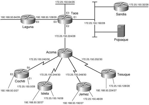 The other Ethernet at each site is a member of network 192.168.50.0 and will have no more than 25 hosts. Subnets 192.168.50.64/26 and 192.168.50.128/26 are being used, which leaves 192.168.50.0/26 and 192.168.50.192/26. By increasing the mask to 27 bits, these two subnets can be divided into four, each with five host bitsenough for 30 host addresses per subnet. Table 6-4 shows the four subnets in binary.
Having assigned all subnet addresses, the next concern is the fact that the subnets of 192.168.50.0 are discontiguous. Chapter 5 presents a case study on discontiguous subnets and demonstrates how to use secondary interfaces to connect them. Classless routing protocols have no such difficulties with discontiguous subnets. Because each route update includes a mask, subnets of one major network can be advertised into another major network. The default behavior of RIPv2, however, is to summarize at network boundaries the same as RIPv1. To turn off summarization and allow subnets to be advertised across network boundaries, use the command no auto-summary with the RIP process. The configuration for Cochiti is displayed in Example 6-7. Example 6-7. Cochiti's configuration with no automatic summarization.interface Ethernet0 ip address 192.168.50.1 255.255.255.224 ! interface Ethernet1 ip address 172.25.150.1 255.255.255.240 ! interface Serial0 ip address 172.25.150.242 255.255.255.252 ! router rip version 2 network 172.25.0.0 network 192.168.50.0 no auto-summary Isleta, Jemez, and Tesuque will have similar configurations. Summarization must also be turned off at Taos and at Acoma. Recall from Figure 6-12 that Laguna was running RIPv1. For this configuration to work, it must be changed to Version 2. Careful consideration should be given to what effect the variable masks will have on Pojoaque, where RIPv1 continues to run. The debug messages in Example 6-8 show the Version 1 and Version 2 updates sent from Taos onto subnet 172.25.150.192/28. The Version 1 updates will include only those subnets whose masks are 28 bits, the same as the subnet on which the updates are being broadcast. Although Pojoaque will not receive advertisements for 172.25.150.64/26 or any of the serial link subnets, an analysis of those subnet addresses shows that Pojoaque will, in this case, correctly interpret the addresses as being different from its own subnet. Packets destined for these subnets will be sent to Taos for routing. Example 6-8. Although the RIPv2 update from Taos includes all subnets in the network, the RIPv1 update includes only a summary route to network 192.168.50.0 and only those subnets of 172.25.150.0 whose masks are the same as the interface on which the update is being sent.Taos#debug ip rip RIP protocol debugging is on RIP: sending v1 update to 255.255.255.255 via Ethernet0 (172.25.150.193) subnet 172.25.150.0, metric 3 subnet 172.25.150.16, metric 3 subnet 172.25.150.32, metric 2 subnet 172.25.150.48, metric 3 subnet 172.25.150.128, metric 3 subnet 172.25.150.192, metric 1 subnet 172.25.150.224, metric 1 network 192.168.50.0, metric 1 RIP: sending v2 update to 224.0.0.9 via Ethernet0 (172.25.150.193) 172.25.150.0/28 -> 0.0.0.0, metric 3, tag 0 172.25.150.16/28 -> 0.0.0.0, metric 3, tag 0 172.25.150.32/28 -> 0.0.0.0, metric 2, tag 0 172.25.150.48/28 -> 0.0.0.0, metric 3, tag 0 172.25.150.64/26 -> 0.0.0.0, metric 1, tag 0 172.25.150.128/28 -> 0.0.0.0, metric 3, tag 0 172.25.150.192/28 -> 0.0.0.0, metric 1, tag 0 172.25.150.224/28 -> 0.0.0.0, metric 1, tag 0 172.25.150.240/30 -> 0.0.0.0, metric 2, tag 0 172.25.150.244/30 -> 0.0.0.0, metric 2, tag 0 172.25.150.248/30 -> 0.0.0.0, metric 2, tag 0 172.25.150.252/30 -> 0.0.0.0, metric 2, tag 0 192.168.50.0/27 -> 0.0.0.0, metric 3, tag 0 192.168.50.32/27 -> 0.0.0.0, metric 3, tag 0 192.168.50.64/26 -> 0.0.0.0, metric 2, tag 0 192.168.50.128/26 -> 0.0.0.0, metric 1, tag 0 192.168.50.192/27 -> 0.0.0.0, metric 3, tag 0 192.168.50.224/27 -> 0.0.0.0, metric 3, tag 0Case Study: AuthenticationThe Cisco implementation of RIPv2 message authentication includes the choice of simple password or MD5 authentication, and the option of defining multiple keys, or passwords, on a "key chain." The router may then be configured to use different keys at different times. The steps for setting up RIPv2 authentication follow:
In Example 6-9, a key chain named Tewa is configured at Taos. Key 1, the only key on the chain, has a password of Kachina; interface E0 then uses the key, with MD5 authentication, to validate updates from Laguna. Example 6-9. Taos's authentication configuration.key chain Tewa key 1 key-string Kachina interface Ethernet 0 ip rip authentication key-chain Tewa ip rip authentication mode md5 A key chain must be configured, even if there is only one key on it. Although any routers that will exchange authenticated updates must have the same password, the name of the key chain has significance only on the local router. Laguna, for instance, might have a key chain named Keres, but the key string must be Kachina to speak to Taos. If the command ip rip authentication mode md5 is not added, the interface will use the default clear text authentication. Although clear text authentication may be necessary to communicate with some RIPv2 implementations, it is almost always wise to use the far more secure MD5 authentication whenever possible. Key management is used to migrate from one authentication key to another. In Example 6-10, Laguna is configured to begin using the first key at 4:30 p.m. on July 1, 2004, for 12 hours (43200 seconds). The second key becomes valid at 4:00 a.m. on July 2, 2004, and will be used until 1:00 p.m. on December 31, 2004. The third key becomes valid at 12:30 p.m. on December 31, 2004, and will remain valid permanently after that. Example 6-10. Laguna's authentication configuration.key chain Keres key 1 key-string Kachina accept-lifetime 16:30:00 Jul 1 2004 duration 43200 send-lifetime 16:30:00 Jul 1 2004 duration 43200 key 2 key-string Kiva accept-lifetime 04:00:00 Jul 2 2004 13:00:00 Dec 31 2004 send-lifetime 04:00:00 Jul 2 2004 13:00:00 Dec 31 2004 key 3 key-string Koshare accept-lifetime 12:30:00 Dec 31 2004 infinite send-lifetime 12:30:00 Dec 31 2004 infinite ! interface Ethernet0 ip address 198.168.50.130 255.255.255.192 ip rip authentication key-chain Keres ip rip authentication mode md5 As the configuration shows, the password that is accepted from other routers and the password that is used with transmitted messages are managed separately. Both the accept-lifetime and the send-lifetime commands must have a specified start time and may have either a specified duration or end time or the keyword infinite. The key numbers are examined from the lowest to the highest, and the first valid key is used. Although this configuration uses a 30-minute overlap to compensate for differences in system times, it is highly recommended that a time synchronization protocol such as Network Time Protocol (NTP) be used with key management.[12]
|
EAN: 2147483647
Pages: 233