Operation of Integrated IS-IS
| The ISO often uses different terms than the IETF to describe the same entities, a fact that can sometimes cause confusion. ISO terms are introduced and defined in this section, but in most cases the more familiar IETF terminology used throughout the rest of this book is used in this chapter.[7] Some ISO terms are so fundamental that they should be discussed before getting into any specifics of the IS-IS protocol.
A router is an Intermediate System (IS), and a host is an End System (ES). Accordingly, a protocol that provides communication between a host and a router is known as ES-IS, and a protocol that routers use to speak to each other (a routing protocol) is IS-IS (Figure 10-1). Whereas IP uses router discovery mechanisms, such as Proxy ARP, IRDP, or in the case of IPv6 NDP, or simply has a default gateway configured on hosts, CLNP uses ES-IS to form adjacencies between End Systems and Intermediate Systems. ES-IS has no relevance to IS-IS for IP and is not covered in this book. Figure 10-1. Hosts are End Systems in ISO terminology, and routers are Intermediate Systems. An interface attached to a subnetwork is a Subnetwork Point of Attachment (SNPA). An SNPA is somewhat conceptual because it actually defines the point at which subnetwork services are provided, rather than an actual physical interface. The conceptual nature of SNPAs fits with the conceptual nature of subnetworks themselves, which can consist of multiple data links connected by data-link switches. A data unit passed from an OSI layer of one node to the peer OSI layer of another node is called a Protocol Data Unit (PDU). So a frame is a Data Link PDU (DLPDU), and a packet is a Network PDU (NPDU). The data unit that performs the equivalent function of the OSPF LSA is the Link State PDU (LSP).[8] Unlike LSAs, which are encapsulated behind an OSPF header and then an IP packet, an LSP is itself a packet.
IS-IS AreasAlthough both IS-IS and OSPF use areas to create a two-level hierarchical topology, a fundamental difference exists in the way in which the two protocols define their areas. OSPF area borders are marked by routers, as shown in Figure 10-2. Some interfaces are in one area, and other interfaces are in another area. When an OSPF router has interfaces in more than one area, it is an Area Border Router (ABR). Figure 10-2. OSPF area borders fall within routers, and the routers that connect the areas are ABRs. Figure 10-3 shows the same topology as shown in Figure 10-2 but with IS-IS areas. Notice that all the routers are completely within an area, and the area borders are on links, not on routers. The IS-IS "backbone area" is a Level 2 area, while non-backbone areas are Level 1 areas. Figure 10-3. IS-IS areas fall on links, and the routers that connect the areas are level 2 routers. An intermediate system can be a level 1 (L1) router, a level 2 (L2) router, or both (L1/L2). L1 routers are analogous to OSPF nonbackbone Internal Routers, L2 routers are analogous to OSPF backbone routers, and L1/L2 routers are analogous to OSPF ABRs. In Figure 10-3, the L1/L2 routers are connected to L1 routers and to L2 routers. These L1/L2 routers must maintain both a level 1 link-state database and a level 2 link-state database, in much the same way that an OSPF ABR must maintain a separate database for each area to which it is attached. Cisco routers are configured as L1-only, L2-only, or L1/L2 with the command is-type. By default, they are L1/L2. While the area topology shown in Figure 10-3 is useful for contrasting IS-IS areas with OSPF areas, it can also be slightly misleading; IS-IS areas are not quite as clear-cut as OSPF areas are. Rather than think of them as topological areas, IS-IS areas are best thought of as a set of adjacencies. An adjacency, in turn, can be either L1 or L2. So, for example, a given L1 area is actually a contiguous set of L1 adjacencies between routers with the same AID. This is especially important for understanding L2 areas, which are always defined as a set of L2 adjacencies. An L1/L2 router, then, is a router in an L1 area that has both one or more L1 adjacencies and one or more L2 adjacencies. An L2 router is one that has only L2 adjacencies. It is also possible for both an L1 and an L2 adjacency to exist between two neighbors; because IS-IS areas are defined as a series of adjacencies, the implication of having both an L1 and an L2 adjacency between the same two neighbors is that IS-IS areas can overlap. This is in contrast to OSPF, in which area boundaries are more distinct. As with OSPF, inter-area traffic must traverse an L2 area to prevent inter-area routing loops. Every L1 router within an area (including the area's L1/L2 routers) maintains an identical link-state database. Unlike OSPF ABRs, L1/L2 routers do not by default advertise L2 routes to L1 routers. Therefore, an L1 router has no knowledge of destinations outside of its own area. In this sense, an L1 area is similar to an OSPF totally stubby area. To route a packet to another area, an L1 router must forward the packet to an L1/L2 router. When an L1/L2 router sends its level 1 LSP into an area, it signals other L1 routers that it can reach another area by setting a bit known as the Attached (ATT) bit[9] in the LSP.
ISO 10589 describes a procedure by which IS-IS routers can create virtual links to repair partitioned areas, just as OSPF can. This feature is not supported by Cisco or by most other router vendors and is not further described here. The primary reason vendors do not support IS-IS virtual links is simply that their customers have not asked for them, and this goes to a fundamental difference in OSPF and IS-IS application. OSPF, with its rich area utilities and feature set, is the protocol of choice for enterprise networks. Multi-area IS-IS, on the other hand, is more complex to run and so is seldom if ever found in enterprise networks. Carriers and ISPs run BGP-based networks, and their IGP is used mainly for finding BGP session endpoints. So they want their IGP to be as simple as possibleoften making their entire routing domain a single IGP area. IS-IS is certainly simpler than OSPF in many aspects, and many will argue that it is more scalable in this type of "single large area" application. So when you encounter IS-IS in a service provider network, what you will usually encounter is a single L2 area.[10]
Because an IS-IS router resides completely within a single area, the Area ID (or area address) is associated with the entire router rather than an interface. A unique feature of IS-IS is that a router can have, by default, up to three area addresses, which can be useful during area transitions. Using the IOS command max-area-addresses, you can increase an area's addresses up to 254. A configuration case study later in this chapter, "An Area Migration," demonstrates the use of multiple area addresses. Each IS-IS router must also have a way to uniquely identify itself within the routing domain. This identification is the function of the System ID, which is analogous to the OSPF Router ID. Both the Area ID and the System ID are defined on an IS-IS router by a single address, the Network Entity Title (NET). Network Entity TitlesEven when IS-IS is used to route only TCP/IP, IS-IS is still an ISO CLNP protocol. Consequently, the packets by which IS-IS communicates with its peers are CLNS PDUs, which in turn means that even in an IP-only environment, an IS-IS router must have an ISO address. The ISO address is a network address, known as Network Entity Title (NET), described in ISO 8348.[11] The length of a NET can range from 8 to 20 octets; the NET describes both the Area ID and the System ID of a device, as shown in Figure 10-4.
Figure 10-4. The NET specifies the Area ID and the System ID of an IS or ES. The ISO designed the NET to be many things to many systems, and depending upon your viewpoint, the address format is either extremely flexible and scalable or it is a cumbersome muddle of variable fields. Figure 10-5 shows just three of the many forms an ISO NET can take. Although the fields preceding the System ID are different in each example, the System ID itself is the same. ISO 10589 specifies that the field can be from one to eight octets in length, but that the System ID of all nodes within the routing domain must use the same length. In practice, the length is always six octets[12] and is often adapted from the Media Access Control (MAC) identifier of an interface on the device. The System ID must be unique for each node within the routing domain.
Figure 10-5. Three NET formats: A simple eight-octet Area ID/System ID format (a); an OSI NSAP format (b); and a GOSIP NSAP format[13] (c).
Also of interest in the examples of Figure 10-5 is the NSAP Selector (SEL). In each case, this one-octet field is set to 0x00. A Network Service Access Point (NSAP) describes an attachment to a particular service at the network layer of a node. So when the SEL is set to something other than 0x00 in an ISO address the address is an NSAP address. This situation is similar to the combination of IP destination address and IP protocol number in an IP packet, which addresses a particular service at the network layer of a particular device's TCP/IP stack. When the SEL is set to 0x00 in an ISO address, the address is a NET, the address of a node's network layer itself. As the variety of formats in Figure 10-5 implies, a detailed discussion of the configuration of NETs is beyond the scope of this book. A good reference for further study is RFC 1237.[14] In an IP-only environment, the NET might be assigned based on a standard such as GOSIP. If you are free to choose any NET for an IP-only environment, choose the simplest format that will serve the needs of your network.
Regardless of the format, the following three rules apply:
IS-IS Functional OrganizationOne of the primary reasons for having a layered network architecture like the OSI model is so that the functions of each layer are independent from the layer below. The network layer, for example, must adapt to many types of data links, or subnetworks. To further this adaptability, the network layer consists of two sublayers (Figure 10-6). The Subnetwork Independent sublayer provides consistent, uniform network services to the transport layer. The Subnetwork Dependent sublayer accesses the services of the data-link layer on behalf of the Subnetwork Independent sublayer. As the two names imply, the Subnetwork Dependent sublayer depends upon a specific type of data link, so that the Subnetwork Independent sublayer can be independent of the data link. Figure 10-6. The OSI network layer consists of two sublayers. The organization of the network layer, specified in ISO 8648,[15] is actually more complex than that shown in Figure 10-6. The two basic sublayers are introduced here because ISO 10589 presents much of its description of the operation of IS-IS within the framework of the functions of these sublayers.
Subnetwork Dependent FunctionsThe subnetwork dependent functions are, of course, the functions of the Subnetwork Dependent sublayer. Their job is to hide the characteristics of different kinds of data links (subnetworks) from the functions of the Subnetwork Independent sublayer. The following subnetwork dependent functions are important to routing:
In contrast to the four network types defined by OSPF, IS-IS defines only two: broadcast subnetworks and point-to-point or general topology subnetworks. Broadcast subnetworks are defined the same as they are under OSPFmulti-access data links that support multicasting. Point-to-point (nonbroadcast) subnetworks can be permanent, such as a T1 link, or dynamically established, such as X.25 SVCs. Neighbors and AdjacenciesIS-IS routers discover neighbors and form adjacencies by exchanging IS-IS Hello PDUs. Hellos are transmitted every 10 seconds, and on Cisco routers this interval can be changed on a per interface basis with the command isis hello-interval. Although IS-IS Hellos are slightly different for broadcast and point-to-point subnetworks, the Hellos include the same essential information, described in the section "IS-IS PDU Formats." An IS-IS router uses its Hello PDUs to identify itself and its capabilities and to describe the parameters of the interface on which the Hellos are sent. If two neighbors are in agreement about their respective capabilities and interface parameters, they become adjacent. IS-IS is, however, less strict than OSPF in accepting adjacencies. In most cases, capabilities advertised by one neighbor but not supported by the other neighbor will not prevent an adjacency from forming; the capability is just ignored. The neighbors can even advertise different Hello intervals. IS-IS forms separate adjacencies for L1 and L2 neighbors. L1-only routers form L1 adjacencies with L1 and L1/L2 neighbors, and L2-only routers form L2 adjacencies with L2 and L1/L2 neighbors. Neighboring L1/L2 routers can form both an L1 adjacency and an L2 adjacency. An L1-only router and an L2-only router will not establish an adjacency. As mentioned previously, Cisco routers are by default L1/L2. While the type of router (L1-only, L2-only, or L1/L2) influences the type of adjacency that is formed, so do the area IDs configured on the two neighbors in question. The following rules apply:
Once an adjacency is established, the Hellos act as keepalives. Each router sends a hold time in its Hellos, informing its neighbors how long they should wait to hear the next Hello before declaring the router dead. The default hold time on Cisco routers is three times the Hello interval and can be changed on a per interface basis with the command isis hello-multiplier. A significant difference from OSPF is that the hello intervals and hold times between two IS-IS neighbors do not have to match. Each router honors the hold time advertised by its neighbor. Another interesting difference between OSPF and IS-IS adjacencies is when two routers become adjacent. OSPF can be a bit confusing here; two routers are considered adjacent as soon as two-way communication is established, but not fully adjacent until database synchronization is completed. IS-IS considers routers adjacent as soon as they have exchanged Hellos. The IS-IS neighbor table can be observed with the command show clns is-neighbors (Example 10-1). The first four columns of the display show the System ID of each neighbor, the interface on which the neighbor is located, the state of the adjacency, and the adjacency type. The state will be either Init, indicating that the neighbor is known, but is not adjacent, or Up, indicating that the neighbor is adjacent. The priority is the router priority used for electing a Designated Router on a broadcast network, as described in the next section. Example 10-1. The command show clns is-neighbors displays the IS-IS neighbor table.Brussels#show clns is-neighbors System Id Interface State Type Priority Circuit Id Format 0000.0C04.DCC0 Se0 Up L1 0 06 Phase V 0000.0C04.DCC0 Et1 Up L1 64 0000.0C76.5B7C.03 Phase V 0000.0C0A.2C51 Et0 Up L2 64 0000.0C76.5B7C.02 Phase V 0000.0C0A.2AA9 Et0 Up L1L2 64/64 0000.0C76.5B7C.02 Phase V Brussels#The sixth column shows the Circuit ID, a one-octet number that the router uses to uniquely identify the IS-IS interface. If the interface is attached to a broadcast multiaccess network, the Circuit ID is concatenated with the System ID of the network's Designated Router, and the complete number is known as the LAN ID. In this usage, the Circuit ID is more correctly called the Pseudonode ID. For example, in Example 10-1 the LAN ID of the link attached to interface E0 is 0000.0c76.5b7c.02. The System ID of the Designated Router is 0000.0c76.5b7c, and the Pseudonode ID is 02. The last column indicates the format of the adjacency. For Integrated IS-IS the format will always be Phase V, indicating OSI/DECnet Phase V. The only other adjacency format is DECnet Phase IV. Designated RoutersIS-IS elects a Designated Router (or more officially, a Designated IS) on broadcast multi-access networks for the same reason OSPF does. Rather than having each router connected to the LAN advertise an adjacency with every other router on the network, the network itself is considered a routera pseudonode. Each router, including the Designated Router, advertises a single link to the pseudonode. The DR also advertises, as the representative of the pseudonode, a zero-cost link to all of the attached routers. Unlike OSPF, however, an IS-IS router attached to a broadcast multi-access network establishes adjacencies with all of its neighbors on the network, not just the DR. This is in keeping with the mention in the previous section that IS-IS adjacencies are established as soon as Hellos are exchanged. Each router multicasts its LSPs to all of its neighbors, and the DR uses a system of PDUs called Sequence Number PDUs (SNPs) to ensure that the flooding of LSPs is reliable. The reliable flooding process, and SNPs, are described in a later section, "Update Process." The IS-IS Designated Router election process is quite simple. Every IS-IS router interface is assigned both an L1 priority and an L2 priority in the range of 0 to 127. Cisco router interfaces have a default priority of 64 for both levels, and this value can be changed with the command isis priority. The router advertises its priority in the Hellos sent from each interfacethe L1 priority is advertised in L1 Hellos, and the L2 priority is advertised in L2 Hellos. Unlike OSPF, in which a priority of 0 makes the router ineligible to become the DR, an IS-IS router with a priority of 0 is merely the lowest priority, but can still become the DR. Interfaces to nonbroadcast networks, on which a DR is not elected, always have a priority of 0 (notice the priority of the serial interface in Example 10-1). The router with the highest priority becomes the DR. In a tie, the router whose attached interface has the numerically highest MAC address becomes the DR. As the L1 and L2 priorities suggest, separate DRs are elected on a network for level 1 and level 2. This outcome is necessary because of the separate L1 and L2 adjacencies that can exist on a single LAN, as shown in Figure 10-7. Because an interface can have separate priorities for each level, the L1 DR and the L2 DR on a LAN might or might not be the same router. Figure 10-7. Separate adjacencies are established for level 1 and for level 2, so separate DRs must be elected for level 1 and level 2.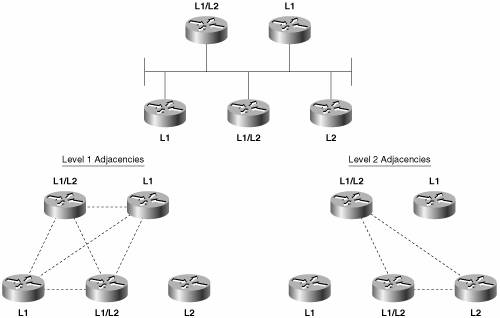 The DR assigns the LAN ID to the network. As discussed in the preceding section, the LAN ID is a concatenation of the DR's System ID and its Pseudonode ID for the attached network. All other routers on the network will use the LAN ID assigned by the DR. Example 10-2 shows the neighbor table of a router whose E0 interface is attached to the same network as the E0 interface of the router of Example 10-1. By comparing these two tables, you can see that three routers are attached to the Ethernet: 0000.0c0a.2aa9, 0000.0c0a.2c51, and 0000.0c76.5b7c. All have a priority of 64, so the one with the numerically highest MAC address is the DR. That router, 0000.0c76.5b7c, identifies the network with Circuit ID 02. Therefore, the LAN ID shown in both Example 10-1 and Example 10-2 is 0000.0c76.5b7c.02. Appending the Circuit ID to the System ID is necessary because the same router can be the DR on more than one network. Notice in Example 10-1 that the same router is the DR on the network attached to E0 and the network attached to E1. It is the Circuit ID, 02 on E0 and 03 on E1, which makes the LAN ID unique for each network. Example 10-2. The E0 interface of this router is attached to the same network as the E0 interface of the router in Example 10-1.London#show clns is-neighbors System Id Interface State Type Priority Circuit Id Format 0000.0C76.5B7C Et0 Up L2 64 0000.0C76.5B7C.02 Phase V 0000.0C0A.2AA9 Et0 Up L2 64 0000.0C76.5B7C.02 Phase V 0000.3090.6756 Se0 Up L1 0 02 Phase V London#The IS-IS DR process is more primitive (or less complex, depending upon one's viewpoint) than the OSPF DR process in two ways. First, IS-IS does not elect a Backup Designated Router. If the IS-IS DR fails, a new DR is elected. Second, the IS-IS DR is not as stable as the OSPF DR. If an OSPF router becomes active on a network with an existing DR, the new router will not become the DR even if its priority or Router ID is higher. As a result, the OSPF DR usually is the router that has been active on the network for the longest time. In contrast to the OSPF rules, a new IS-IS router with a higher priority than the existing DR, or an equal priority and a higher MAC address, will become the new DR. Each time the DR is changed, a new set of LSPs must be flooded. However, given that adding a new router to a broadcast link is a relatively uncommon occurrence in the operational day of a network, and that DR election happens very quickly in modern routerson the order of microsecondsthe lack of a BDR and the fact that a DR can be preempted should not be a cause for concern. Subnetwork Independent FunctionsThe functions of the subnetwork-independent sublayer define how CLNS delivers packets throughout the CLNP network and how these services are offered to the transport layer. The routing function itself is divided into four processes: the Update process, the Decision process, the Forwarding process, and the Receive process. As the names of the last two processes suggest, the Forwarding process is responsible for transmitting PDUs, and the Receive process is responsible for the reception of PDUs. These two processes, as described in ISO 10589, are more relevant to CLNS NPDUs than to IP packets, and so are not described further. Update ProcessThe Update process is responsible for constructing the L1 and L2 link-state databases. To do so, L1 LSPs are flooded throughout the area in which they are originated, and L2 LSPs are flooded over all L2 adjacencies. The specific fields of the LSPs are described in the section "IS-IS PDU Formats." Each LSP contains a Remaining Lifetime, a Sequence Number, and a Checksum. The Remaining Lifetime is an age. The difference between an IS-IS LSP's Remaining Lifetime and an OSPF LSA's Age parameter is that the LSA Age increments from zero to MaxAge, whereas the LSP Remaining Lifetime begins at MaxAge and decrements to zero. The IS-IS MaxAge is 1200 seconds (20 minutes). Like OSPF, IS-IS ages each LSP as it resides in the link-state database, and the originator must periodically refresh its LSAs to prevent the Remaining Lifetime from reaching zero. The IS-IS refresh interval is 15 minutes minus a random jitter of up to 25 percent. If the Remaining Lifetime reaches zero, the expired LSP will be kept in the link-state database for 60 seconds, known as the ZeroAgeLifetime. An interesting and important difference from the OSPF LSA refresh process is that because the IS-IS Remaining Lifetime begins as a non-zero number and is decremented down to zero, the beginning number can be changed from its default of 1200 seconds. In fact, it can be increased up to 65,535 secondsapproximately 18.2 hours. This is a major contributing factor to IS-IS scalability in very large areas. If the area links are reasonably stable, increasing the refresh time and the Remaining Lifetime can sharply reduce the flooding load caused by LSP refreshes. The initial Remaining Lifetime (MaxAge) value that is set in locally originated LSPs is changed with the command max-lsp-lifetime, and the period between refreshes of locally originated LSPs is set with the command lsp-refresh-interval. If you change the defaults, always set the refresh interval at least a few hundred seconds less than the Remaining Lifetime so that newly refreshed LSPs arrive at all routers in the area before the old instances of the LSPs age out. Under older IS-IS procedures, if any router receives an LSP with an incorrect checksum, the router will purge the LSP by setting the LSP's Remaining Lifetime to zero and reflooding it. The purge causes the LSP's originator to send a new instance of the LSP. However, the second edition of ISO 10589 does away with purging LSPs with incorrect checksums because on error-prone subnetworks, allowing receiving routers to initiate purges can significantly increase the LSP traffic. IOS implementations before 12.0 follow the older purging procedure, but you can override this behavior with the command ignore-lsp-errors. When a router with this option enabled receives a corrupted LSP, it drops it rather than purging it. The originator of the corrupted LSP will still know that the LSP was not received through the use of SNPs, described later in this section. As of 12.0, the newer IS-IS procedures are implemented and ignore-lsp-errors is enabled by default. A significant point about the LSP purging, however, is yet another way that IS-IS differs from OSPF, where only the originator can purge an OSPF LSA. The Sequence Number is an unsigned, 32-bit linear number. When a router first originates an LSP, it uses a Sequence Number of one, and each subsequent instance of the LSP has its Sequence Number incremented by one. If the Sequence Number increments to the maximum (0xFFFFFFFF), the IS-IS process must shut down for at least 21 minutes (MaxAge + ZeroAgeLifetime) to allow the old LSPs to age out of all databases. On point-to-point subnetworks, routers send L1 and L2 LSPs directly to the neighboring router. On broadcast subnetworks, the LSPs are multicast to all neighbors. Frames carrying L1 LSPs have a destination MAC identifier of 0180.c200.0014, known as AllL1ISs. Frames carrying L2 LSPs have a destination MAC identifier of 0180.c200.0015, known as AllL2ISs. IS-IS uses SNPs both to acknowledge the receipt of LSPs, to request LSPs, and to help maintain link-state database synchronization. There are two types of SNPs: Partial SNPs (PSNP) and Complete SNPs (CSNP). On a point-to-point subnetwork, a router uses a PSNP to explicitly acknowledge each LSP it receives.[16] The PSNP describes the LSP it is acknowledging by including the following information:
When a router sends an LSP on a point-to-point subnetwork, it sets a timer for a period known as minimumLSPTransmissionInterval. If the timer expires before the router receives a PSNP acknowledging receipt of the LSP, a new LSP will be sent. On Cisco routers, the default minimumLSPTransmissionInterval is five seconds. It can be changed on a per interface basis with the command isis retransmit-interval. The default value is almost always the right value; the occasional exception is if a neighbor regularly struggles to process a large number of LSPs. In this case the router might not acknowledge an LSP fast enough, triggering a retransmit and just adding to its problems. In this case, increasing the minimumLSPTransmissionInterval can help; but in the long run, the real solution to such a problem is upgrading the low-powered neighbor. On broadcast subnetworks, LSPs are not acknowledged by each receiving router. Instead, the DR periodically multicasts a CSNP that describes every LSP in the link-state database. The default CSNP period is 10 seconds, which can be changed with the command isis csnp-interval. L1 CSNPs are multicast to AllL1ISs (0180.c200.0014), and L2 CSNPs are multicast to AllL2ISs (0180.c200.0015). When a router receives a CSNP, it compares the LSPs summarized in the PDU with the LSPs in its database. If the router has an LSP that is missing from the CSNP or a newer instance of an LSP, the router multicasts the LSP onto the network. If another router sends the updated LSP first, however, the router will not send another copy of the same LSP. If the router's database does not contain a copy of every LSP listed in the CSNP or if the database contains an older instance of an LSP, the router multicasts a PSNP listing the LSPs it needs. Although the PSNP is multicast, only the DR responds with the appropriate LSPs. An interesting feature of IS-IS is its ability to signal other routers if it runs out of memory and cannot record the complete link-state database. The memory overload might be due to an area that has been allowed to grow too large, a router with insufficient memory, or a transitory condition such as the failure of a DR. If a router cannot store the complete link-state database, it will set a bit in its LSP called the Overload (OL) bit. The OL bit signals that the router might not be able to make correct routing decisions because of its incomplete database. The other routers still route packets to the overloaded router's directly connected networks, but do not use the router for transit traffic until it has issued an LSP with the OL bit cleared. Because a set OL bit prevents the router from being used as a hop along a route, the bit is frequently called the hippity bit (as in hippity-hop, believe it or not). Memory should be allocated equally to the L1 and the L2 database, but a router can be in an overload condition at one level and normal in the other. This overload feature is an artifact of the days when routers did not have much memory. Modern routers are unlikely to become overloaded. However, the OL bit serves another very useful purpose in modern networks, particularly in BGP networks. To understand the problem, it is necessary to understand a few basic concepts of BGP. While link-state protocols such as IS-IS converge very quickly, BGP converges slowlysometimes taking several minutes. In the interior of a BGP network, routes have next-hop addresses that can be several router hops away. When a packet arrives, its destination is looked up in the BGP routes. The next hop of the BGP route must then be looked up in the IGP routes before the packet can be forwarded. Now suppose that a new router is added to the network, and the IGP has converged but BGP has not yet finished. If another router determines that this new router is on the best path to a BGP next-hop, based on the converged IGP routes, it will forward packets to the router to be forwarded along to the next-hop address. But if BGP has not yet converged in the new router, the router might not have a BGP route for the packet and might drop it, resulting in black-holed traffic. By setting the IS-IS OL bit until BGP has converged, you can avoid this problem. Other routers, if the OL bit is set, will route around the new router. Once BGP is converged, the OL bit can be cleared and packets can be forwarded through the new router. Using the command set-overload-bit on-startup, you can specify a number of seconds by which the OL bit is set whenever IS-IS starts. When the specified seconds expire, the OL bit is automatically cleared. By setting the OL bit at around 300 to 500 seconds, you ensure that BGP will converge before the OL bit is cleared. There is an alternative command, set-overload-bit on-startup wait-for-bgp, which always clears the OL bit as soon as BGP converges. While more dynamic than using a static number of seconds, this option can have a vulnerability: If one BGP session does not come up for some reason, the OL bit will never be cleared. So it is usually best to specify seconds rather than the wait-for-bgp option. You can also set the OL bit manually and indefinitely by using the set-overload-bit command with no other options specified. This can be useful in situations where you want the router to be attached to an IS-IS network and receive a full database, but you do not want the router to be used in any forwarding path. A lab router attached to a production network is an example of such an application. The command show isis database displays a summary of the IS-IS link state database, as shown in Example 10-3. The router Brussels in this display is an L1/L2 router, so it has both L1 and L2 databases. The LSP ID shown in the first column consists of the System ID of the originating router, concatenated with two more octets. The first octet following the System ID is the Pseudonode ID. If this octet is nonzero, the LSP was originated by a DR. The System ID and the nonzero Pseudonode ID together make the LAN ID of a broadcast subnetwork. Example 10-3. The IS-IS database can be observed with the command show isis database.Brussels#show isis database IS-IS Level-1 Link State Database LSPID LSP Seq Num LSP Checksum LSP Holdtime ATT/P/OL 0000.0C04.DCC0.00-00 0x00000036 0x78AE 1152 0/0/0 0000.0C0A.2AA9.00-00 0x0000011B 0x057B 416 0/0/0 0000.0C76.5B7C.00-00* 0x00000150 0xD5D4 961 1/0/0 0000.0C76.5B7C.02-00* 0x00000119 0xD9C3 407 0/0/0 0000.0C76.5B7C.03-00* 0x000000FA 0x896E 847 0/0/0 IS-IS Level-2 Link State Database LSPID LSP Seq Num LSP Checksum LSP Holdtime ATT/P/OL 0000.0C0A.2AA9.00-00 0x0000013E 0x319A 666 0/0/0 0000.0C0A.2C51.00-00 0x00000133 0x762D 654 0/0/0 0000.0C76.5B7C.00-00* 0x0000014C 0x4E91 886 0/0/0 0000.0C76.5B7C.02-00* 0x0000011F 0x3CC3 1174 0/0/0 0000.3090.C7DF.00-00 0x0000011A 0xDDF0 858 0/0/0 Brussels#The last octet is the LSP Number. Occasionally, an LSP can be so large that it exceeds the MTU that can be supported by the router buffers or the data link. In this case, the LSP is fragmentedthat is, the information is conveyed in multiple LSPs. The LSP IDs of these multiple LSPs consist of identical System IDs and Pseudonode IDs, and distinct LSP Numbers. An asterisk following the LSP ID indicates that the LSP is originated by the router on which the database is being observed. For example, the database shown in Example 10-3 is taken from a router named Brussels. The L1 LSP with an ID of 0000.0c76.5bB7c.00-00 is originated by Brussels, as are four other LSPs. The second and third columns of the database display show the Sequence Number and checksum of each LSP. The fourth column, LSP Holdtime, is the Remaining Lifetime of the LSP in seconds. If you enter the show isis database command repeatedly, you can observe the numbers decrementing. When the LSP is refreshed, the Remaining Lifetime is reset to 1200 seconds and the Sequence Number is incremented by one. The last column indicates the state of the Attached (ATT) bit, Partition (P) bit, and Overload (OL) bit of each LSP. L2 and L1/L2 routers will set the ATT bit to one to indicate that they have a route to another area. The P bit indicates that the originating router has partition repair capability. Cisco (and most other vendors) does not support this function, so the bit is always set to zero. The OL bit is set to one if the originating router is experiencing a memory overload and has an incomplete link-state database, or if the OL bit has been manually set. A complete LSP can be observed by using the command show isis database detail along with the level and the LSP ID, as shown in Example 10-4. The meanings of the individual fields of the LSP are given in the section "IS-IS PDU Formats." Example 10-4. The command show isis database detail is used to observe complete LSPs in the database.London#show isis database detail level-2 0000.0C0A.2C51.00-00 IS-IS Level-2 LSP 0000.0C0A.2C51.00-00 LSPID LSP Seq Num LSP Checksum LSP Holdtime ATT/P/OL 0000.0C0A.2C51.00-00* 0x0000013B 0x6635 815 0/0/0 Area Address: 47.0001 NLPID: 0x81 0xCC IP Address: 10.1.3.2 Metric: 10 IS 0000.0C76.5B7C.02 Metric: 10 IP 10.1.3.0 255.255.255.0 Metric: 20 IP 10.1.2.0 255.255.255.0 Metric: 10 IP 10.1.255.4 255.255.255.252 Metric: 20 IP 10.1.255.0 255.255.255.0 Metric: 30 IP 10.1.255.8 255.255.255.252 London#Decision ProcessOnce the Update process has built the link-state database, the Decision process uses the information in the database to calculate a shortest-path tree. The process then uses the shortest-path tree to construct a forwarding database (route table). Separate SPF calculations are run for the L1 database and the L2 database. ISO 10589 specifies the following metrics (one required and three optional) to be used by IS-IS to calculate the shortest path:
Each metric is expressed as an integer between 0 and 63, and a separate route is calculated for each metric. Therefore, if a system supports all four metrics, the SPF calculation must be run four times for both the L1 database and the L2 database. Because of the potential for many iterations of the SPF calculation for every destination, resulting in many different route tables, and because the optional metrics provide rudimentary Type of Service routing at best, Cisco supports only the default metric. Cisco assigns a default metric of 10 to every interface, regardless of the interface type. The command isis metric changes the value of the default metric, and the default can be changed separately for level 1 and level 2. If the metrics are left at 10 for every interface, every subnetwork is considered equal and the IS-IS metric becomes a simple measure of hop count, where each hop has a cost of 10. The total cost of a route is a simple sum of the individual metrics at each outgoing interface, and the maximum metric value that can be assigned to any route is 1023. This small maximum is frequently pointed out as a limitation of IS-IS because it leaves little room for metric granularity in large networks. However, newer extensions to IS-IS allow for a much larger metric spacecalled wide metricsof 32 bits. To set wide metrics, the command metric-style wide is used. IS-IS not only classifies routes as L1 or L2 but also classifies routes as internal or external. Internal routes are paths to destinations within the IS-IS routing domain, and external routes are paths to destinations external to the routing domain. Whereas L2 routes may be either internal or external, L1 routes are normally internal; using a routing policy you can make an L1 route external, but this should only be done with good justification and with special care. Given multiple possible routes to a particular destination, an L1 path is preferred over an L2 path. Within each level, a path that supports the optional metrics is preferred over a path that supports only the default metric. (Again, Cisco supports only the default metric, so the second order of preference is not relevant to Cisco routers.) Within each level of metric support, the path with the lowest metric is preferred. If multiple equal-cost, equal-level paths are found by the Decision process, they are all entered into the route table. The Cisco IS-IS implementation usually performs equal-cost load balancing on up to six paths. The previous section, "Update Process," discussed the last octet of the LSP ID, known as the LSP Number, used to track fragmented LSPs. The Decision process pays attention to the LSP Number for several reasons. First, if an LSP with an LSP Number of zero and a nonzero Remaining Lifetime is not present in the database, the Decision process will not process any LSPs from the same system that have nonzero LSP Numbers. For example, if the LSP IDs 0000.0c76.5b7c.00-01 and 0000.0c76.5b7c.00-02 exist in the database, but the database contains no LSP with an LSP ID of 0000.0c76.5b7c.00-00, the first two LSPs are not processed. This approach ensures that incomplete LSPs do not cause inaccurate routing decisions. Also, the Decision process will accept the following information only from LSPs whose LSP Number is zero:
The Decision process ignores these settings in LSPs whose LSP Number is nonzero. In other words, the first LSP in a series of fragments speaks for all the fragments for these three settings. Example 10-5 shows a route table from a Cisco IS-IS router. Notice that the L1 and L2 routes are indicated and that three destinations have multiple paths. A mask is associated with each route, indicating support for VLSM. Finally, the route table indicates that the administrative distance of IS-IS routes is 115. Example 10-5. This route table shows both level 1 and level 2 IS-IS routes.Brussels#show ip route Codes: C - connected, S - static, I - IGRP, R - RIP, M - mobile, B - BGP D - EIGRP, EX - EIGRP external, O - OSPF, IA - OSPF inter area E1 - OSPF external type 1, E2 - OSPF external type 2, E - EGP i - IS-IS, L1 - IS-IS level-1, L2 - IS-IS level-2, * - candidate default Gateway of last resort is not set 10.0.0.0 is variably subnetted, 8 subnets, 3 masks C 10.1.3.0 255.255.255.0 is directly connected, Ethernet0 i L2 10.1.2.0 255.255.255.0 [115/30] via 10.1.3.2, Ethernet0 [115/30] via 10.1.3.3, Ethernet0 i L1 10.1.5.0 255.255.255.0 [115/20] via 0.0.0.0, Serial0 [115/20] via 10.1.4.2, Ethernet1 C 10.1.4.0 255.255.255.0 is directly connected, Ethernet1 i L2 10.1.255.4 255.255.255.252 [115/20] via 10.1.3.2, Ethernet0 i L2 10.1.255.0 255.255.255.0 [115/30] via 10.1.3.2, Ethernet0 i L1 10.1.255.8 255.255.255.252 [115/20] via 10.1.3.3, Ethernet0 i L1 10.1.6.240 255.255.255.240 [115/20] via 0.0.0.0, Serial0 [115/20] via 10.1.4.2, Ethernet1 Brussels#Another duty of the Decision process in L1 routers is to calculate the path to the nearest L2 router, for inter-area routing. As previously discussed, when an L2 or L1/L2 router is attached to another area, the router will advertise the fact by setting the ATT bit in its LSP to one. The Decision process in L1 routers will choose the metrically closest L1/L2 router as the default inter-area router. When IS-IS is used to route IP, a default IP route to the L1/L2 is entered into the route table. For example, Example 10-6 shows a link-state database for an L1 router and its associated route table. LSP 0000.0c0a.2c51.00-00 has an ATT = 1. Based upon this information, the Decision process has chosen the router with System ID 0000.0c0a.2c51 as the default inter-area router. The route table shows a default route (0.0.0.0) via 10.1.255.6, with a metric of 10. Although it is not readily apparent from the information shown in Example 10-6, 10.1.255.6 and System ID 0000.0c0a.2c51 refer to the same router. Example 10-6. Integrated IS-IS adds a default IP route to the nearest L1/L2 router whose ATT bit is set to one.Paris#show isis database IS-IS Level-1 Link State Database LSPID LSP Seq Num LSP Checksum LSP Holdtime ATT/P/OL 0000.0C0A.2C51.00-00 0x0000016D 0xA093 730 1/0/0 0000.3090.6756.00-00* 0x00000167 0xC103 813 0/0/0 0000.3090.6756.04-00* 0x0000014E 0x227F 801 0/0/0 0000.3090.C7DF.00-00 0x00000158 0x78A6 442 0/0/0 Paris#show ip route Codes: C - connected, S - static, I - IGRP, R - RIP, M - mobile, B - BGP D - EIGRP, EX - EIGRP external, O - OSPF, IA - OSPF inter area E1 - OSPF external type 1, E2 - OSPF external type 2, E - EGP i - IS-IS, L1 - IS-IS level-1, L2 - IS-IS level-2, * - candidate default Gateway of last resort is 10.1.255.6 to network 0.0.0.0 10.0.0.0 is variably subnetted, 5 subnets, 2 masks i L1 10.1.3.0 255.255.255.0 [115/20] via 10.1.255.6, Serial0 C 10.1.2.0 255.255.255.0 is directly connected, TokenRing0 i L1 10.1.255.4 255.255.255.252 [115/20] via 10.1.255.6, Serial0 C 10.1.255.0 255.255.255.0 is directly connected, Serial0 i L1 10.1.255.8 255.255.255.252 [115/20] via 10.1.2.2, TokenRing0 i*L1 0.0.0.0 0.0.0.0 [115/10] via 10.1.255.6, Serial0 Paris#The information in Example 10-6 illustrates an interesting characteristic of working with Integrated IS-IS, particularly when troubleshooting. Although TCP/IP is the protocol being routed, the protocol determining the routes, including all the route control packets and addresses, is a CLNS protocol. Sometimes correlating the CLNS information with the IP information can be difficult. One command that can be useful is which-route. The command is used primarily to determine the route table in which a particular CLNS destination is located. However, which-route can also yield useful information about the IP addresses associated with a particular CLNS address. In Example 10-7, the System ID/Circuit ID 0000.0c0a.2c51.00, shown in the database of Example 10-6 as having ATT = 1, is used as the argument to which-route. The result shows, among other things, that the next-hop address for the queried System ID is 10.1.255.6. Example 10-7. The command which-route can reveal some information tying CLNS addresses to IP addresses.Paris#which-route 0000.0C0A.2C51.00 Route look-up for destination 00.000c.0a2c.5100 Using route to closest IS-IS level-2 router Adjacency entry used: System Id SNPA Interface State Holdtime Type Protocol 0000.0C0A.2C51 *HDLC* Se0 Up 26 L1 IS-IS Area Address(es): 47.0001 IP Address(es): 10.1.255.6 Uptime: 22:08:52 Paris#IS-IS PDU FormatsIS-IS uses nine PDU types in its processes, and each PDU is identified by a five-bit type number. The PDUs fall into three categories, as shown in Table 10-1.
The first eight octets of all of the IS-IS PDUs are header fields that are common to all PDU types, as shown in Figure 10-8. These first fields are described here, and the PDU-specific fields are described in subsequent sections. Figure 10-8. The first eight octets of the IS-IS PDUs. Intradomain Routeing Protocol Discriminator is a constant assigned by ISO 9577[17] to identify NPDUs. All IS-IS PDUs have a value of 0x83 in this field.
Length Indicator specifies the length of the fixed header in octets. Version/Protocol ID Extension is always set to one. ID Length describes the length of the System ID field of NSAP addresses and NETs used in this routing domain. This field is set to one of the following values:
The System ID of Cisco routers must be six octets, so the ID Length field of a Cisco-originated PDU will always be zero. PDU Type is a five-bit field containing one of the PDU type numbers shown in Table 10-1. The preceding three bits (R) are reserved and are always set to zero. Version is always set to one, just like the Version/Protocol ID Extension in the third octet. Reserved is always set to all zeroes. Maximum Area Addresses describes the number of area addresses permitted for this IS area. The number is set to one of the following values:
Cisco IOS supports a maximum of three areas by default, so the Maximum Area Addresses field in IS-IS PDUs originated by Cisco routers will always be zero unless the default has been changed with the max-area-addresses command. In Figure 10-9, an analyzer capture of an IS-IS PDU shows the first eight octets of the PDU. Figure 10-9. This analyzer capture shows the first eight fields of an IS-IS PDU, along with its data-link header. The PDU-specific fields following the common header fields are also part of the header; they vary according to PDU type and are discussed in the sections dealing with specific PDU types. TLV FieldsThe variable-length fields following the PDU-specific fields are Type/Length/Value (TLV)[18] triplets, as shown in Figure 10-10. The Type (or Code)[19] is a number specifying the information content of the value field, the Length specifies the length of the Value field, and the Value field is the information itself. As the one-octet size of the Length field implies, the maximum size of the Value field is 255 octets.
Figure 10-10. IS-IS TLV triplets perform the same function for IS-IS as TLV triplets perform for EIGRP. Table 10-2 lists the basic IS-IS TLV codes. The table also indicates whether the TLV is specified in ISO 10589 or in RFC 1195. The ISO-specified TLVs are designed for use with CLNP, although most of them are also used with IP. The RFC-specified TLVs are designed only for IP. If a router does not recognize a particular TLV code, it will ignore the TLV. This arrangement allows TLVs for CLNP, IP, or both to be carried in the same PDU.
Although many of the TLVs are used by more than one IS-IS PDU type, only one (Authentication) is used by all PDUs. As the formats of the IS-IS PDUs are described in the following sections, the TLVs used by each PDU are listed. The format of each TLV is described only once, the first time it is listed. Table 10-3 summarizes which TLVs are used with which PDUs.
The great advantage of using TLVs is that to add new capabilities to IS-IS, you need only add new TLV types. Since it was first specified, there have been many enhancements to IS-IS. Table 10-4 lists many of the TLVs that have been added since ISO 10589 and RFC 1195 first specified IS-IS. Also listed are the RFCs specifying the new TLVs and what they are used for. In some cases, the extensions are new enough that at this writing they are still in Internet-Draft form. By the time you are reading this chapter, they might be RFCs; check the IETF website (www.ietf.org) Linked Varified to find out. Some of the extensions listed in Table 10-4 are detailed in subsequent sections of this chapter, and some are not.
IS-IS Hello PDU FormatThe purpose of the IS-IS Hello PDU is to allow IS-IS routers to discover IS-IS neighbors on a link. Once the neighbors have been discovered and have become adjacent, the job of the Hello PDU is to act as a keepalive to maintain the adjacency and to inform the neighbors of any changes in the adjacency parameters. The upper limit on the size of an IS-IS PDU is defined by either the buffer size of the originating router or the MTU of the data link on which the PDU is transmitted. ISO 10589 specifies that IS-IS Hellos must be padded, using type 8 Padding TLVs, to within one octet less than this maximum, partly to allow a router to implicitly communicate its MTU to its neighbors. More important, sending Hellos at or near the link MTU is intended to help detect link failure modes in which small PDUs pass but larger PDUs are dropped. If a neighboring interface does not support the minimum required MTU, the padded Hellos are dropped and no adjacency is established. There are two kinds of IS-IS Hellos: LAN Hellos and point-to-point Hellos. The LAN Hellos can be further divided into L1 and L2 LAN Hellos. The format of the two types of LAN Hellos is identical, as shown in Figure 10-11. Figure 10-12 shows an analyzer capture of a level 2 LAN Hello. Figure 10-11. The IS-IS LAN Hello PDU format. Figure 10-12. This analyzer capture of a LAN Hello shows the fields unique to a Hello PDU.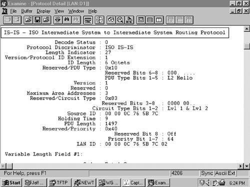 Circuit Type is a two-bit field (the preceding six bits are reserved and are always zero) specifying whether the router is an L1 (01), L2 (10), or L1/L2 (11). If both bits are zero (00), the entire PDU is ignored. Source ID is the System ID of the router that originated the Hello. Holding Time is the period a neighbor should wait to hear the next Hello before declaring the originating router dead. PDU Length is the length of the entire PDU in octets. Priority is a seven-bit field used for the election of a DR. The field carries a value between 0 and 127 with the higher number having the higher priority. L1 DRs are elected by the priority in L1 LAN Hellos, and L2 DRs are elected by the priority in L2 LAN Hellos. LAN ID is the System ID of the DR plus one more octet (the Pseudonode ID) to differentiate this LAN ID from another LAN ID that might have the same DR. The following TLVs can be used by an IS-IS LAN Hello:[20]
Figure 10-13 shows the format of the IS-IS point-to-point Hello PDU. It is almost identical to the LAN Hello, except that there is no Priority field and there is a Local Circuit ID field instead of a LAN ID field. Unlike LAN Hellos, L1 and L2 information is carried in the same point-to-point Hello PDU. The point-to-point Hello carries all of the same TLVs, with the exception of the Intermediate System Neighbors TLV. Instead, if the IS-IS implementation supports the associated extension, the point-to-point Hello carries a P2P Three-Way Adjacency (type 240) TLV. The use of this TLV is described in the later section "3-Way Handshaking." Figure 10-13. The IS-IS point-to-point Hello PDU. Local Circuit ID is a one-octet ID assigned to this circuit by the router originating the Hello and is unique among the router's interfaces. The Local Circuit ID in the Hellos at the other end of the point-to-point link might or might not contain the same value. Area Addresses TLVThe Area Addresses TLV (Figure 10-14) is used to advertise the area addresses configured on the originating router. As the multiple Address Length/Area Address fields imply, a router can be configured with multiple area addresses. Figure 10-14. The Area Addresses TLV. Figure 10-15 shows part of an IS-IS Hello PDU; Variable Length Field #3 is an Area Addresses TLV with a total length of six octets. There are two area addresses: 47.0002 (three octets), and 0 (one octet). Figure 10-15. An Area Addresses TLV is shown as Variable Length Field #3. The analyzer also indicates the total addresses listed in the TLV (2) for convenience, but this information is not one of the TLV fields.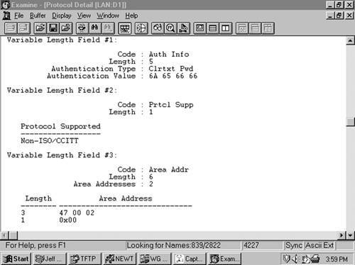 Intermediate System Neighbors TLV (Hello)The IS Neighbors TLV (Figure 10-16) lists the System IDs of all neighbors from whom a Hello has been heard within the last Hold Time. Note that this TLV gives the IS-IS LAN Hello a function similar to the OSPF function of listing all recently-heard-from neighbors, to verify two-way communication. Figure 10-16. The IS Neighbors TLV for Hello PDUs. This TLV is used only in LAN Hellos; it is not carried in point-to-point Hellos, where no DR election is performed. It is also different from the IS Neighbors TLV used by LSPs, and the two are distinguished by their type numbers. L1 LAN Hellos list L1 neighbors only, and L2 LAN Hellos list L2 neighbors. The neighbors listed in this TLV are identified by the MAC address of their interfaces on the LAN. Variable Length Field #5 in Figure 10-17 shows an IS Neighbors TLV in which a single neighbor, 0000.0c0a.2aa9, is listed. Figure 10-17. An IS Neighbors TLV is shown as Variable Length Field #5.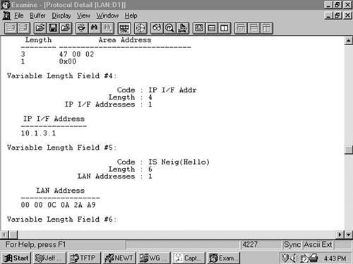 Padding TLVThe Padding TLV is used to pad a Hello PDU out to either the minimum allowed IS-IS size of 1492 bytes or the MTU of the link. Since the maximum size of a Value field is 255 octets, multiple Padding TLVs are often used. The bits in the Value field can be arbitrary because they are ignored; Cisco sets all these bits to zero (Figure 10-18). Figure 10-18. The last Variable Length Fields of the Hello PDU shown in Figure 10-12 are Padding TLVs, which bring the size of the PDU to the 1497-octet length shown in Figure 10-12. With the addition of the 3-octet LLC header and the 18-octet Ethernet header, the entire frame size is the 1518-octet Ethernet MTU.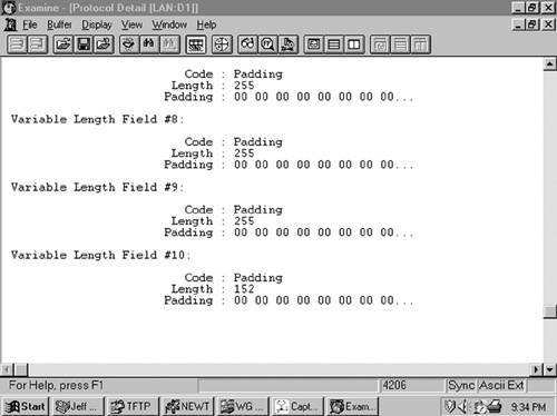 Authentication Information TLVThe Authentication Information TLV (Figure 10-19) is used when authentication is configured. The Authentication Type field contains a number between 0 and 255 that specifies the type of authentication used and hence the type of information contained in the Authentication Value field. IOS supports either clear-text password authentication or, HMAC-MD5 encrypted hash authentication. Clear-text passwords are Authentication Type 1, and HMAC-MD5 is Authentication Type 54. Figure 10-19. The Authentication Information TLV. Variable Length Field #1 in Figure 10-15 is an Authentication Information TLV. The password is "jeff," which is displayed as the hex representation of its ASCII characters. Protocols Supported TLVThe Protocols Supported TLV (Figure 10-20) is specified in RFC 1195, and its original purpose was to indicate whether the originator of the PDU supports CLNP only, IP only, or both. Since that time, the TLV is also used to indicate support for IPv6. The IPv4 NLPID is 204 (0xCC) and the IPv6 NLPID is 142 (0x8E). For each protocol supported, the corresponding one-octet Network Layer Protocol Identifier (NLPID), specified in ISO/TR 9577, is listed in the TLV. IP is 0x81. Variable Length Field #2 in Figure 10-15 is a Protocols Supported TLV. Figure 10-20. The Protocols Supported TLV. IP Interface Address TLVThe IP Interface Address TLV (Figure 10-21) contains the IP address or addresses of the interface out which the PDU was sent. Because the Length field is one octet, an interface of an IS-IS router can theoretically have up to 63 IP addresses. Variable Length Field #4 in Figure 10-17 is an IP Interface Address TLV, indicating that the captured Hello PDU was transmitted from an interface with an address of 10.1.3.1. Figure 10-21. The IP Interface Address TLV. IS-IS Link State PDU FormatThe IS-IS LSP performs essentially the same function as the OSPF LSA. An L1 router floods an L1 LSP throughout an area to identify its adjacencies and the state of those adjacencies. An L2 router floods L2 LSPs throughout the level 2 domain, identifying adjacencies to other L2 routers and address prefixes that the advertising L2 router can reach. Figure 10-22 shows the format of the IS-IS LSP. The format is the same for both L1 LSPs and L2 LSPs. Figure 10-22. The IS-IS LSP format. PDU Length is the length of the entire PDU in octets. Remaining Lifetime is the number of seconds before the LSP is considered to be expired. LSP ID is the System ID, the Pseudonode ID, and the LSP Number of the LSP. The LSP ID is described in more detail in section "Update Process." Sequence Number is a 32-bit unsigned integer. Checksum is the checksum of the contents of the LSP. P is the Partition Repair bit. Although the bit exists in both L1 and L2 LSPs, it is relevant only in L2 LSPs. When this bit is set, it indicates that the originating router supports the automatic repair of area partitions. Cisco IOS does not support this function, so the P bit of LSPs originated by Cisco routers will always be zero. ATT is a four-bit field indicating that the originating router is attached to one or more other areas. Although the bits exist in both L1 and L2 LSPs, they are relevant only in L1 LSPs that have been originated by L1/L2 routers. The four bits indicate which metrics are supported by the attachment. Reading from left to right, the bits indicate
Cisco IOS supports only the default metric, so bits 5 through 7 will always be zero. OL is the Link State Database Overload bit. Under normal circumstances, this bit will be zero. Routers receiving an LSP with the OL bit set will not use the originating router as a transit router, although they will still route to destinations on the originator's directly connected links. IS Type is a two-bit field indicating whether the originating router is an L1 or an L2:
An L1/L2 router sets the bits according to whether the LSP is an L1 or an L2 LSP. The following TLVs can be used by an L1 LSP:
The following TLVs can be used by an L2 LSP:
Figure 10-23 shows an L1 LSP that was originated by an L1/L2 router. Figure 10-23. Analyzer capture of an LSP.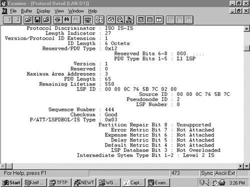 Intermediate System Neighbors TLV (LSP)The Intermediate System Neighbors TLV used by LSPs (Figure 10-24) lists the originating router's IS-IS neighbors (including pseudonodes) and the metrics of the router's link to each of its neighbors. Figure 10-24. Intermediate System Neighbors TLV for LSPs. Virtual Flag, although eight bits long, has a value of either 0x01 or 0x00. A 0x01 in this field indicates that the link is a level 2 virtual link to repair an area partition. The field is relevant only to L2 routers that support area partition repair; Cisco does not, so the field will always be 0x00 in Cisco-originated LSPs. R is a reserved bit and is always zero. I/E, associated with each of the metrics, indicates whether the associated metric is internal or external. The bit has no meaning in IS Neighbors TLVs because all neighbors are by definition internal to the IS-IS domain. Therefore, this bit is always zero in IS Neighbors TLVs. Default Metric is the six-bit default metric for the originating router's link to the listed neighbor and contains a value between 0 and 63. S, associated with each of the optional metrics, indicates whether the metric is supported (zero) or unsupported (one). Cisco does not support any of the three optional metrics, so the bit is always set to one and the associated six-bit metric fields are all zeroes. Neighbor ID is the System ID of the neighbor, plus one more octet. If the neighbor is a router, the last octet is 0x00. If the neighbor is a pseudonode, the System ID is that of the DR and the last octet is the Pseudonode ID. Figure 10-25 shows part of an IS Neighbors TLV. Figure 10-25. Part of an IS Neighbors TLV in an LSP.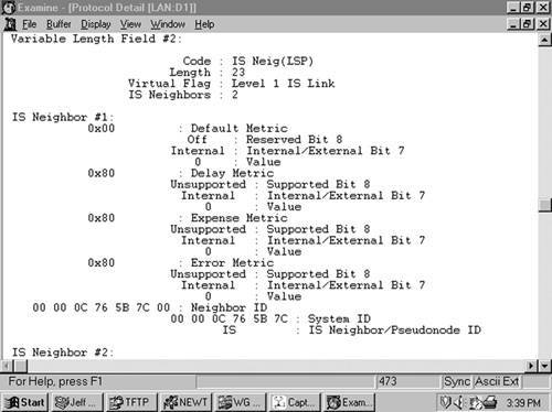 IP Internal Reachability Information TLVThe IP Internal Reachability Information TLV (Figure 10-26) lists IP addresses and associated masks within the routing domain that are directly connected to the advertising router. The TLV is used by both L1 and L2 LSPs, but never appears in an LSP describing a pseudonode. The metric fields are identical to the IS Neighbors TLV, except that no I/E bit is associated with the optional metrics. Instead, the bit is reserved and is always zero. Like the IS Neighbors TLV, the I/E bit in this TLV is always zero because the addresses advertised in the TLV are always internal. Figure 10-27 shows an analyzer capture of an IP Internal Reachability Information TLV. Figure 10-26. IP Internal Reachability Information TLV. Figure 10-27. Analyzer capture of an IP Internal Reachability Information TLV.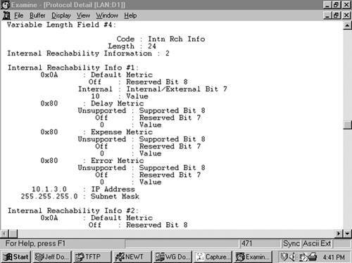 IP External Reachability Information TLVThe IP External Reachability Information TLV lists IP addresses and associated masks external to the routing domain, which can be reached via one of the originating router's interfaces. Its format is identical to the Internal Reachability Information TLV shown in Figure 10-26 except for the code, which is 130. The I/E bit determines the metric type for all four metricsI/E = 0 for internal metrics and I/E = 1 for external metrics. Inter-Domain Routing Protocol Information TLVThe Inter-Domain Routing Protocol Information TLV (Figure 10-28) allows L2 LSPs to transparently carry information from external routing protocols through the IS-IS domain. The TLV serves the same purpose as the Route Tag fields of RIPv2, EIGRP, and OSPF packets. Route tagging is covered in Chapter 14, "Route Maps." Figure 10-28. The Inter-Domain Routing Protocol Information TLV. Inter-Domain Information Type specifies the type of information contained in the variable-length External Information field. If the type field is 0x01, the External Information is of a format used by the local interdomain routing protocol. Chapter 14 includes examples of using route maps to set such local information. If the type field is 0x02, the External Information is a 16-bit autonomous system number, which is used to tag all subsequent External IP Reachability entries until either the end of the LSP or the next occurrence of the Inter-Domain Routing Protocol Information TLV. IS-IS Sequence Numbers PDU FormatSNPs are used to maintain the IS-IS link-state database by describing some or all of the LSPs in the database. They are also used, in some cases, to request LSPs and to implicitly or explicitly acknowledge received LSPs. So SNPs have a function similar to OSPF Link State Request, Database Description, and Link State Acknowledgment messages. A DR periodically multicasts a CSNP (Figure 10-29) to describe all the LSPs in the pseudonode's database. Because there is an L1 database and an L2 database, CSNPs are also either L1 or L2. Some link-state databases can be so large that the LSPs cannot all be described in a single CSNP. For this reason, the last two fields of the CSNP header are the Start LSP ID field and the End LSP ID field, which together describe the range of LSPs described in the CSNP. Figure 10-30 shows how these two fields are used. In this CSNP, the full database is described; therefore, the LSP ID range starts with 0000.0000.0000.00.00 and ends with ffff.ffff.ffff.ff.ff. If two CSNPs were required to describe the database, the range of the first CSNP might be something like 0000.0000.0000.00 to 0000.0c0a.1234.00.00 and the range of the second CSNP might be 0000.0c0a.1234.00.01 to ffff.ffff.ffff.ff.ff. Figure 10-29. The IS-IS CSNP format. Figure 10-30. This analyzer capture shows the header of an L1 CSNP.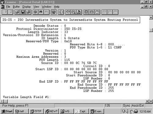 A PSNP (Figure 10-31) is similar to a CSNP, except that the former describes only some LSPs rather than the entire database. Therefore, no Start and End fields are necessary as they are with CSNPs. A router sends a PSNP on a point-to-point subnetwork to acknowledge received LSPs. On a broadcast subnetwork, PSNPs request missing or more recent LSPs. Like CSNPs, there are both L1 and L2 PSNPs. Figure 10-31. IS-IS PSNP format. Only four TLVs are used by SNPs, whether they are CSNP or PSNP and whether they are L1 or L2:
LSP Entries TLVThe LSP Entries TLV (Figure 10-32) summarizes an LSP by listing its Remaining Lifetime, LSP ID, Sequence Number, and Checksum. These fields not only identify the LSP but also completely identify a particular instance of an LSP. Figure 10-33 shows part of an LSP Entries TLV. Figure 10-32. LSP Entries TLV. Figure 10-33. Part of the LSP Entries TLV of the CSNP in Figure 10-30.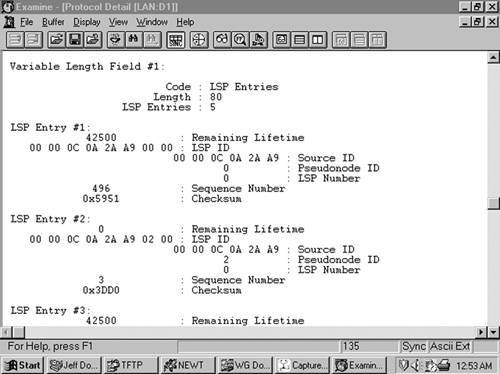 Extensions to IS-ISAs you have already seen in Table 10-4 and the associated discussion, a number of extensionseither to support optional capabilities or to improve the basic mechanisms of IS-IShave been added since the protocol was first extended to support IPv4. In this section we explore the most important of those extensions. One of the nice things about basic IS-IS behavior is that unlike OSPFv2's LSAs, if IS-IS encounters a TLV that it does not understand, it just ignores it. This makes extendability and backward-compatibility much easier in IS-IS. If you are migrating your network to support a new feature, or simply have one router that understands an extension and another that does not, there is much less worry that adjacencies would be effected than with OSPFv2. You also saw in Chapter 9, "OSPFv3," that OSPFv3 has adopted at least some of this same behavior, making the protocol more forgiving than OSPFv2. 3-Way HandshakingBefore neighbors become adjacent, they must ensure that there is two-way communication between them. The process for ensuring this is called handshaking. It is not enough to simply send and receive Hellos, which is two-way handshaking; it is possible that your neighbor is not receiving the Hellos you send. So three-way handshaking, in which there is some explicit acknowledgment that your neighbor has received your Hellos, is required. OSPF always uses three-way handshaking, by listing in transmitted Hellos the neighbors that it has received Hellos from. So if an OSPF router sees its RID listed in the Neighbor field of a received Hello, it knows that the originator of the Hello has received this router's Hellos. Bidirectional communication is confirmed. IS-IS also uses three-way handshaking across broadcast networks. The LAN Hello uses the IS Neighbors TLV to list all neighbors from which a Hello has been received. The TLV then serves the same purpose as the Neighbors list in OSPF Hellos: An IS-IS router that sees its own SysID in the IS Neighbors TLV of a received LAN Hello knows that bidirectional communication is confirmed. But as has already been mentioned, Point-to-Point Hellos do not carry IS Neighbors TLVs. ISO 10589 prescribes only two-way handshaking across point-to-point links, with the admonition that the point-to-point medium should be reliable. In reality, point-to-point links can often be unreliable; certainly we do not want to reject IS-IS as a potential IGP choice just because we might have a link in our network that does not meet some vague reliability requirement. To remedy this problem, RFC 3373 specifies a Point-to-Point Three-Way Adjacency TLV. This type 240 TLV, shown in Figure 10-34, lists the SysIDs of all neighbors known by the originator, and also indicates the originator's perception of the state of its adjacency on the link: Up, Initializing, or Down. Figure 10-34. Point-to-Point Three-Way Adjacency TLV. Domain-Wide Prefix DistributionThe default characteristic of L1 areas, as you read earlier in this chapter, is very much like an OSPF totally stubby area. That is, no prefixes are advertised from L2 to L1; instead, L1/L2 routers set the ATT bit and L1 routers then install a default router to the nearest L1/L2 router. In fact, RFC 1195 specifically prohibits advertising prefixes from L2 to L1. But this is not always acceptable. If there are multiple L1/L2 routers, sometimes you would prefer to pick the one closest to the destination rather than just the closest L1/L2 router exiting the area. For this to happen, the L1 routers must have knowledge of specific prefixes and their costs outside of the local area; and that, in turn, means that prefixes must be advertised from L2 to L1. In IS-IS lingo this is called route leaking. The potential difficulty, and the reason RFC 1195 prohibits such "downward" route leaking, is that if you have more that one L1/L2 router in the L1 areawhich is most likely why you want to leak routes from L2 to L1 in the first placeyou have the potential for inter-area routing loops. Figure 10-35 illustrates the problem. The L1/L2 router Hague learns prefix 192.168.0/24 from some L2 LSP. If it is to advertise the prefix into its L1 area, it must advertise the prefix in its L1 LSP using an IP Internal Reachability TLV. When that L1 TLV is flooded, it is received by Rotterdam, another L1/L2 router. But because the prefix is in an L1 LSP, Rotterdam has no way of knowing that it originated outside of the L1 area. So it advertises the prefix back out to the L2 area in an L2 LSP. A routing loop can now exist in which L2 routers think that a path to 192.168.1.0/24 exists within the L1 area. Figure 10-35. Under basic RFC 1195 rules, a prefix leaked from L2 to L1 is at risk of being advertised back to L2, creating a routing loop. OSPF does not have this problem because prefixes external to a non-backbone area are advertised in type 3 LSAs. Other ABRs do not advertise prefixes learned from type 3 LSAs in a non-backbone area into area 0. RFC 2666 provides a workaround to the problem by defining a bit in the IP Internal Reachability and IP External Reachability TLVs called the Up/Down (U/D) bit. Looking at the format of the IP Internal Reachability TLV in Figure 10-26 (and remembering that the format of the IP External Reachability bit is identical), notice that the octet containing the I/E bit and the 6-bit Default Metric field begins with a reserved bit. This bit becomes the U/D bit, as shown in Figure 10-36. As the type field indicates, the bit is defined for both IP Internal Reachability and IP External Reachability TLVs. Figure 10-36. The eighth bit of the default metric field, previously reserved, is redefined as the Up/Down bit. When an L1/L2 router advertises a route from L2 to L1, it sets the U/D bit. Any other L1/L2 router that receives a prefix with its U/D bit set in an L1 LSP does not advertise the prefix in an L2 LSP. If an L1/L2 router does not understand the U/L bit, it ignores the bit. So it is important, if you are using L2 to L1 route leaking, to ensure that all of your L1/L2 routers understand this extension. The Case Study "Route Leaking Between Levels" later in this chapter demonstrates how to set up L2 to L1 route leaking. Wide MetricsTraffic Engineering (TE) is a function primarily associated with Multiprotocol Label Switching (MPLS) networks in which some subset of packets can be forwarded differently depending on a user-specified set of constraints. In other words, rather than always choosing the single shortest path through a network as an IGP does, traffic flows can be spread out over different paths. This can both help overall bandwidth utilization in a network and enable service differentiationby, for example, ensuring that delay-sensitive flows take the shortest path while other traffic takes longer paths. One of the keys to traffic engineering is the communication of much more detailed interface parameters than just metrics; it makes sense to use an IGP that is already designed for sharing path and interface information to share these TE interface parameters. Both OSPF and IS-IS have been extended to carry TE interface parameters; for IS-IS, two new TLVs are used:
These TLVs, and the TE parameters they support, are specified in RFC 3784. However, MPLS Traffic Engineering is beyond the scope of this book. Nevertheless, these two new TLVs are of interest to us because they provide an important new capability that can be used outside of just Traffic Engineering. As mentioned earlier in this chapter, a concern about IS-IS in its original form is that the six-bit metric field does not allow enough metric granularity for a large network. These new TLVs support a much larger metric space, called wide metrics. The Extended IS Reachability TLV uses a 24-bit metric field, and the Extended IP Reachability TLV uses a 32-bit metric field. The format of the Extended IS Reachability TLV is shown in Figure 10-37. When wide metrics are enabled, this TLV is used in place of the type 2 IS Neighbors TLV in LSPs. Of interest to us is that like the type 2 TLV, it lists neighbors and their metrics for the SPF calculations; notice the 24-bit metric field. The sub-TLV field is for TE parameters, and has no relevance to this discussion. However, it is useful to note that TLVs such as this one do allow nested TLVsthat is, sub-TLVs or TLVs within other TLVs. That's just one more example of the flexibility that TLVs allow developers. Figure 10-37. Extended IS Reachability TLV. The format of the Extended IP Reachability TLV is shown in Figure 10-38. When wide metrics are enabled, this TLV is used in place of both IP Internal Reachability Information and IP External Reachability Information TLVs. Accordingly, this TLV can appear in both L1 and L2 LSPs. You can see in the illustration that prefixes advertised by this TLV can have a metric of up to 32 bits. There is also an Up/Down flag for L2 to L1 route leaking. As with the Extended IS Reachability TLV, the sub-TLV fields only have relevance to Traffic Engineering (the S bit indicates the presence of sub-TLVs). Figure 10-38. Extended IP Reachability TLV.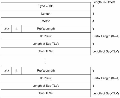 Wide metrics are enabled in IOS with the command metric-style wide. Examples of using wide metrics are shown in this chapter in the Case Studies "A Basic Integrated IS-IS Configuration for IPv6" and "Transition to Multiple Topology Mode." Routing IPv6 with IS-ISIn Chapter 9, you saw that OSPF support for IPv6 requires an entirely new version of OSPF. IS-IS, on the other hand, is easily extended to support IPv6 through the addition of two new TLVs. As of this writing, the IPv6 extension of IS-IS is still in the Internet-Draft stage, but it is likely to be an RFC very soonprobably by the time you are reading this chapter. IS-IS indicates its support of IPv6 by including the IPv6 NLPID 142 (0x8E) in its Protocols Supported TLV. The two TLVs for IPv6 support are
The IPv6 Reachability TLV (Figure 10-39) can be said to serve the same purpose as the IP Internal Reachability Information and IP External Reachability Information TLVs for IPv4. However, the parallel function is actually much closer to the type 135 Extended IP Reachability TLV for two reasons:
Figure 10-39. IPv6 Reachability TLV. You can see in the figure the 32-bit metric field and an Up/Down bit for L2 to L1 route leaking for each prefix. The X bit indicates whether the prefix is internally originated (X = 0) or externally originated (X = 1). The S bit indicates whether sub-TLVs exist. The IPv6 Interface Address TLV, shown in Figure 10-40, is the functional equivalent of the type 132 IP Interface Address TLV for IPv4: It advertises the address of the interface from which the TLV originates. And like its IPv4 counterpart, it can be carried in both Hellos and LSPs. When the TLV appears in Hellos, the addresses it advertises are the link-local addresses of the originating interface. If the TLV appears in LSPs, the addresses it advertises are the non-link-local (site or global scope) addresses of the originating interface. Figure 10-40. IPv6 Interface Address TLV. Even though the IP Interface Address TLV can carry up to 63 32-bit IPv4 addresses, IPv6 addresses are four times as long. That restricts the IPv6 Interface Address TLV to carrying a maximum of 15 IPv6 addresses. An example of configuring IS-IS for IPv6 is provided in the Case Study "A Basic Integrated IS-IS Configuration for IPv6." Dynamic Hostname ExchangeOne operational difficulty when working with IS-IS is that it can be hard to associate the SysIDs in various router displays with the correct router. Identifying IPv4 addresses is not easy, but we tend to be more comfortable with them just through long familiarity. But SysIDs, such as in the display of Example 10-1, are a real challenge. RFC 2763 provides a convenient solution to this challenge by specifying a Dynamic Hostname TLV (type 137). This simple TLV provides, in its value field, up to 255 bits for carrying an ASCII router name. Normally, implementations supporting this extension insert the configured router hostname into the field; the TLV is then carried in any non-pseudonode LSP. When a router display is called up, as in Example 10-8, the ASCII value of the Dynamic Hostname TLV is used instead of the SysID, for easier interpretation. Example 10-8. This re-display of the IS-IS neighbor table of Example 10-1 shows the advantage of the Dynamic Hostname Exchange mechanism.Brussels#show clns is-neighbors System Id Interface State Type Priority Circuit Id Format Dublin Se0 Up L1 0 06 Phase V Amsterdam Et1 Up L1 64 Brussels.03 Phase V Rome Et0 Up L2 64 Brussels.02 Phase V London Et0 Up L1L2 64/64 Brussels.02 Phase V Brussels#Multiple TopologiesModern IP networks often provide multiple services over a common IP infrastructure, using basic service building blocks such as IPv4, IPv6, and multicast. The financial advantages of using a common infrastructure for all services, as opposed to building separate networks for each service, are enormous: Far less capital expenditure, less equipment to maintain, simpler operational procedures, and fewer operations personnel. But often the requirements of the separate basic service building blocks require different routing topologies. Perhaps IPv4 is run everywhere, but IPv6 should be limited to just some parts of the IPv4 domain. Multicast might also need to be limited to some subset of the IPv4 domain, but different from the IPv6 topology. Multi Topology (MT) routing allows you to build these routing subsets on a common infrastructure. The individual topologies are identified by Multi Topology Identifiers (MT IDs). The currently defined MT IDs are listed in Table 10-5. These MT IDs are assigned to router interfaces to indicate what topologies the interface belongs to; each interface can have one or more MT IDs. Adjacencies are not MT specific, but are established between all IS-IS neighbors as usual. But the LSPs are tagged with the appropriate MT IDs, and a separate SPF calculation is run for each topology. In each router, a separate route table is maintained for each topology, and entries are made in them based on the separate PSF calculations.
IS-IS support for MT routing is currently in the Internet-Draft stage. The draft specifies several TLVs for MT support:
When an MT IS-IS router sends Hellos, it includes one or more Multi Topology TLVs (Figure 10-41), one for each topology to which the originating interface belongs. If a neighbor does not include any Multi Topology TLVs in its Hellos, the neighbor is considered to belong only to the default IPv4 topology (MT ID 0). On a point-to-point link, if the two neighbors do not have any MT IDs in common, no adjacency is formed. However, behavior is different on a broadcast link; neighbors form an adjacency even if they have no MT IDs in common. This is because the Designated Router election is independent of the MT IS-IS extensions; a router that does not support the extensions can be elected DR, so all routers at the same level must be adjacent. Figure 10-41. Multi Topology TLV. The Multi Topology TLV is carried not only in Hellos but also in LSPs. As Figure 10-41 shows, the TLV can signal Overloading (with the O bit) and L2 attachment (with the A bit) separately for each topology. The format of the MT Intermediate Systems TLV (Figure 10-42) is exactly the same as that of the Extended IS Reachability TLV, and serves the same purpose, except that there is a separate MT Intermediate Systems TLV for each of the topologies to which the originator belongs. Figure 10-42. MT Intermediate Systems TLV. The MT Reachable IPv4 Prefixes TLV (Figure 10-43) and the MT Reachable IPv6 Prefixes TLV (Figure 10-44) are the functional equivalents of the Extended IP Reachability and IPv6 Reachability TLVs, respectively. They advertise prefixes, but associated with a given topology. Figure 10-43. MT Reachable IPv6 Prefixes TLV. Figure 10-44. MT Reachable IPv6 Prefixes TLV. An example of configuring multiple IS-IS topologies is provided later in this chapter in the Case Study "Transition to Multiple Topology Mode." Mesh GroupsAlthough the technologies are quickly vanishing in favor of SONET and MPLS, Frame Relay and ATM networks are often still used as the core transport media of many large networks. And a topology frequently used in Frame Relay and ATM networks is that the virtual circuits (VCs) used for connectivity are fully meshed as shown in Figure 10-45. But well-meshed or fully meshed networkswhere all routers have connections to all other routersare susceptible to abnormally heavy flooding loads. Figure 10-45. ATM and Frame Relay infrastructures underlying an IP network often are configured so that every node is connected to every other nodethat is, the nodes are fully meshed. Because every router is connected to every other router, when a router floods an LSP every other router immediately receives it, as shown in Figure 10-46. This is as flooding needs to proceed. Figure 10-46. In a fully meshed network, a transmission from one router is immediately received by all other routers. The problem is that the receiving routers have links to other routers, and they have no way of knowing that the flooded LSP has already been received by these other routers. So following the basic split horizon rule for flooding, these other routers flood the LSP out every interface except the one that the LSP was received on, as shown in Figure 10-47. This illustration shows that every router in the network floods n 2 unnecessary LSPs, where n is the number of routers in the network: It floods an LSP to every router except itself and the router from which the LSP was received. As quadratic equations demonstrate, this works out to (n 1)(n 2) or n2 3n + 2 unnecessarily flooded LSPs.[21]
Figure 10-47. Even though every router has received the flooded LSP, they still must follow the rules of flooding and send the LSP to every neighbor except the one from which they received the LSP. In the network we are examining here, the extra flooding load is not that bad: With six routers, n2 3n + 2 = 20 unnecessarily flooded LSPs. But suppose there are 100 fully meshed routers. Now you have n2 3n + 2 = 9,702 unnecessarily flooded LSPs. And this is just from one router refreshing its LSP. Consider every router refreshing its LSPs, possibly multiple LSPs per router, and other activity besides refresh timers triggering LSP floods, and you can see that the unnecessary LSPs at every flood are tremendous. Of course, in a modern network these numbers might not be unreasonable given the overall volume of packets being handled, but to many network architects any inefficiency offends their sense of aesthetics. For these individuals who find beauty in simplicity, RFC 2973 offers mesh groups for IS-IS. The mesh group mechanism allows you to block flooding of an LSP when you are reasonably certain that a router's neighbor has already received the LSP. Mesh groups place the interface in one of three modes:
Inactive mode simply means that although the router supports mesh groups, no mesh groups are enabled for that interface and LSPs are flooded normally. When an interface is in blocked mode, it does not flood any LSPs. Figure 10-48 shows how blocked interfaces might reduce the flooding load of the network of Figure 10-45. Here, the fully meshed topology of Figure 10-45 has been reduced to a "ring" flooding topology; of course, regular packet forwarding can still use the full mesh. In this flooding topology, every router has two neighbors rather than n-1 neighbors. There is still a bit of unnecessary flooding, but it is greatly reduced from the level shown in Figure 10-47. Figure 10-48. Blocking flooding on some interfaces reduces overall flooding load. There is a tradeoff for the partially blocked topology in Figure 10-48there is always a tradeoff. First, while every router has an unblocked flooding link to two other routers, if both of those links fail flooding will be corrupted even though the router has other perfectly good links to neighbors. Second, convergence time can be effected. Although full-mesh flooding as shown in Figure 10-46 ensures that every router receives a flooded LSP as soon as it is sent, the partially blocked flooding topology of Figure 10-48 means that a flooded LSP in some cases must transit one or several routers before all routers have received it. Set mode gives you a bit more flexibility than blocked mode, providing a compromise between the reduced redundancy and increased convergence time of blocked mode while still reducing the flooding loadalthough not as much as blocked mode. In set mode, you define numbered mesh groups and then assign interfaces to the groups. When an LSP is received, it is received on an interface belonging to some numbered group. The LSP is then flooded out all interfaces except interfaces belonging to the same group as the interface on which the LSP was received. Figure 10-49 shows the topology of Figure 10-45 configured into two mesh groups: Group 1 and Group 2. If a router is originating an LSP, it floods the LSP out every interface no matter what group the interface belongs to; so the first flooding looks just like Figure 10-46. Some of the neighbors receive the LSP on an interface belonging to group 1, and some receive it on interfaces belonging to group 2. Figure 10-49. Set mode allows you to create numbered mesh groups by assigning interfaces to groups. The receiving routers then flood the LSP out interfaces belonging to mesh groups other than the one it was received on. If the LSP was received on an interface belonging to group 1, it is only flooded out interfaces belonging to group 2, and vice versa, as shown in Figure 10-50. All of these flooded LSPs are of course unnecessary; every router received a copy of the LSP when the originator initially flooded it. Comparing the flooding pattern to Figure 10-48, you can see that although the unnecessary flooding is heavier than with blocked mode, it is still less than the load depicted in Figure 10-47. And, because the initial flood reached all of the routers, convergence time is not affected. Figure 10-50. A received LSP is flooded on all interfaces except those belonging to the same mesh group as the interface on which it was received. Inactive, blocked, and set mode can be mixed in a complex topology to attain the flooding patterns you want. In practice, blocked mode is used far more often than set mode. But if you choose to use mesh groups at all, be aware that you are in all cases trading some of the robustness of full-mesh flooding for a reduced flooding load. Using IOS, you can block flooding on an interface with the command isis mesh-group blocked or assign the interface to a numbered mesh group with the command isis mesh-group number. Flooding DelaysWhile mesh groups can control the amount of unnecessary LSPs sent during flooding in densely meshed networks, flooding can also become a problem if the network becomes unstable. For example, a quickly and constantly flapping link can cause tremendous flooding of LSPs, each triggering SPF calculations in all area routers, eating up network resources. IOS offers several tools for reducing the impact of flooding in such situations. The first is a means of reducing flooding of locally originated LSPs when the router experiences an instability such as a flapping link. In such a situation, imposing a delay before flooding an LSP might mean that not every flap causes a flood. For example, if a link flaps every 20 seconds but flooding is delayed for one minute, only every fifth flap will cause a flood. But we do not want to always delay flooding; when the network is stable, waiting one minute before flooding a new LSP can cause a serious increase in convergence time. So IOS uses an exponential backoff algorithm in which a very small delay of 50 milliseconds is imposed before the first generation of an LSP. If an event should cause the generation of another LSP within five seconds of the previous generation, the router waits five seconds before generating the new LSP. This delay continues until the network has been calm for 10 seconds, and then the 50 ms generation interval is restored. The default behavior of this exponential backoff can be changed with the command lsp-gen-interval, and the following command options:
While lsp-gen-interval throttles the generation of LSPs during local instabilities, there might also be a problem in which a particular router is underpowered and can be overwhelmed by heavy flooding. The only real solution to this problem is to upgrade the router. But there are options for controlling the flooding to the neighbor in the interim. The first option is the command isis lsp-interval, which changes the default delay between transmissions of LSPs on an interface (and hence to a specific neighbor). The default delay is 33 ms. So, for example, if the delay is set to 100 ms, LSPs cannot be transmitted faster than one every .1 seconds or 10 LSPs per second. There is also the problem of LSP retransmissions, which again applies to underpowered neighbors. If a router is struggling to process received LSPs, it might be delayed in acknowledging the LSPs, causing its neighbors to retransmit the LSPs. If the router was struggling to begin with, the retransmissions would make matters worse. The default wait time before retransmitting an LSP is 5 seconds. An underpowered neighbor can be protected somewhat by increasing the wait time, up to 65,535 seconds, with the command isis retransmit-interval. There might still be a problem in which, even if you had increased the wait time before retransmitting an LSP with the isis retransmit-interval command, the wait time would expire on multiple LSPs and they all would need to be retransmitted. You can regulate the time between the transmission of each of these retransmitted LSPs, in milliseconds, with the command isis retransmit-throttle-interval. So while isis retransmit-interval increases the time to wait for an acknowledgment before retransmitting, isis retransmit-throttle-interval increases the interval between each retransmitted LSP if and when the wait time does expire. Although these commands give you options for controlling flooding, they should be used only in extreme cases. In the great majority of cases the defaults should not be changed; and where tinkering with these values becomes necessary, you should look to the cause. Usually a router upgrade or an improvement in link reliability is the better solution. Improving SPF EfficiencyIOS uses two mechanisms for improving the efficiency of its SPF algorithm:
When a stub router is added to the networkthat is, when a router is added in which there is only one link to itall routers in the area do not need to recalculate the SPF. Instead, it is enough to just add the router to the tree. And if a link that is not already on the SPF tree changes in some way that does not affect the tree, it is unnecessary for routers to run SPF at all. iSPF takes such cases into account, and only runs SPF to the extent that the topological change warrants. iSPF can also limit the scope of an SPF calculation. That is, if a change affects only a limited part of the topology, iSPF can confine the SPF recalculation to that portion of the topology. Another change that does not need to trigger an SPF calculation is the addition, deletion, or metric change of an IP prefix. A router detecting such a change floods an LSP with an IP Reachability TLV (or one of its functional equivalents) to advertise the change. But this LSP does not need to trigger an SPF calculation. This is Partial Route Calculation: Received LSPs are examined, and if there is no topological change requiring an SPF calculation, such as a new IP Reachability TLV or a new IS Neighbors TLV, no SPF calculation is run. In times of network instability, imposing longer delays between SPF runs might span the reception of multiple LSPs. That is, if many LSPs are being flooded, waiting between SPF runs might mean that rather than running SPF every time an LSP is received, the router might receive many LSPs and account for them all with a single SPF run. IOS uses an exponential backoff algorithm like the one used for throttling LSP generation, described in the previous section, for SPF runs. The command spf-interval applies to full SPF runs, and prc-interval for partial route calculations. In both cases, like the LSP generation throttling, you can specify an initial wait, a second wait that is doubled for each subsequent run, and a maximum wait time that cannot be exceeded. The defaults for the SPF exponential backoff are 5500 ms for the initial wait, 5500 ms for the second wait, and 10 seconds for the maximum wait; the defaults for PRC are 2000 ms, 5000 ms, and 5 seconds respectively. However, as with the flooding delays, it is seldom a good idea to change the default values of the SPF delays. The real solutions to overly frequent SPF runs are reliable links and network components, and perhaps the use of areas to reduce flooding scope. | ||||||||||||||||||||||||||||||||||||||||||||||||||||||||||||||||||||||||||||||||||||||||||||||||||||||||||||||||||||||||||||||||||||||||||||||||||||||||||||||||||||||||||||||||||||||||||||||||||||||||||||||||||||||||||||||||||||||||||||||||||||||||||||||||||||||||||||||||||||||||||||||||||||||||||||||||||||||||||||||||||||||||||
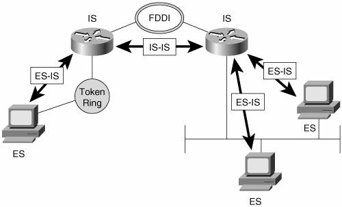
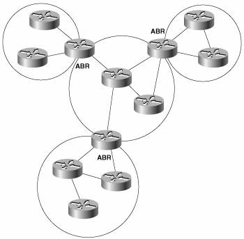
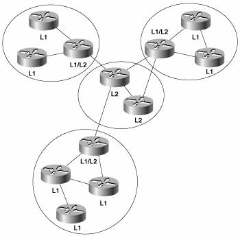
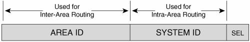
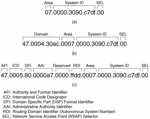
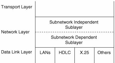
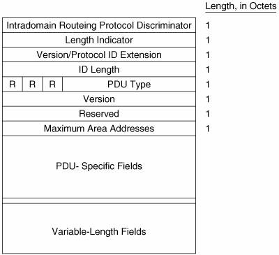
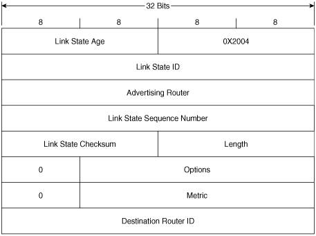
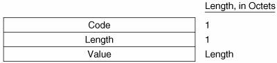
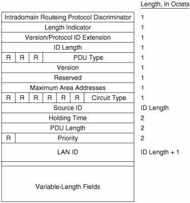
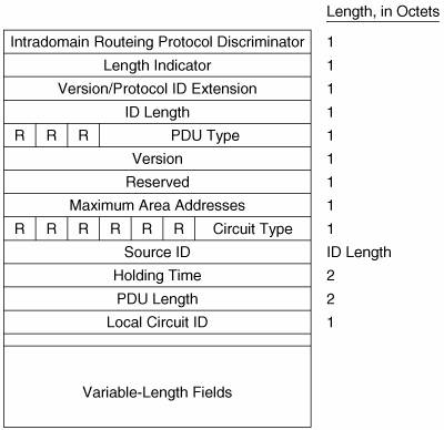
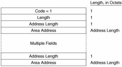
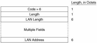
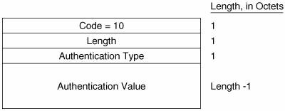
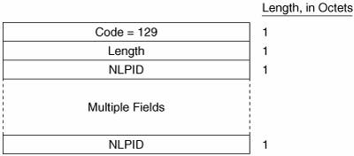
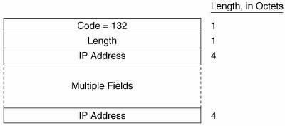
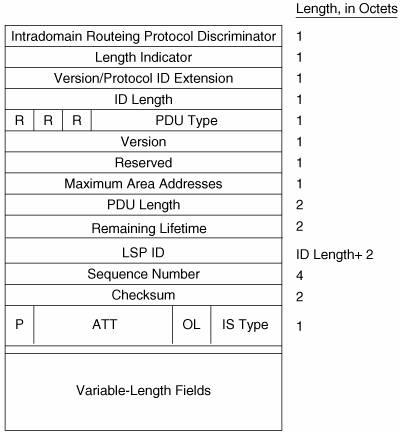
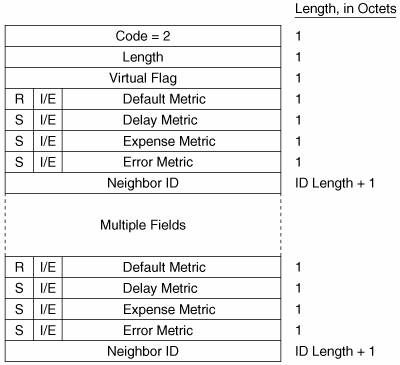
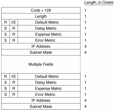
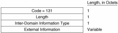
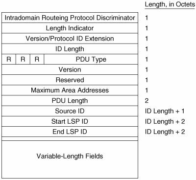
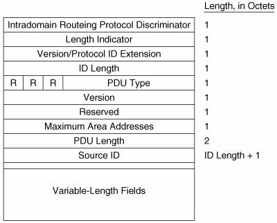
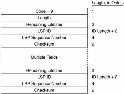
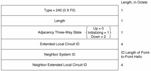
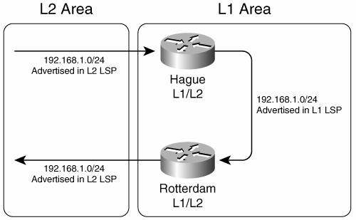
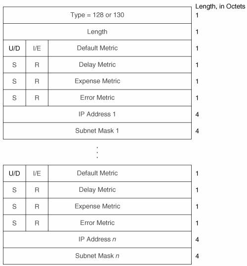
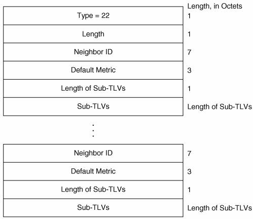
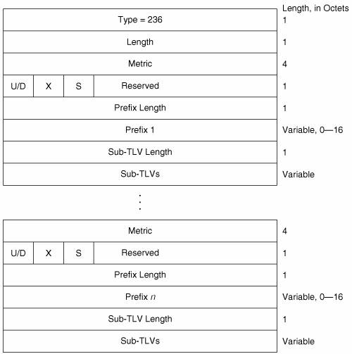
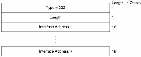
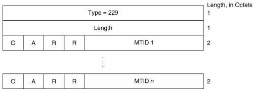
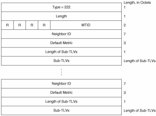
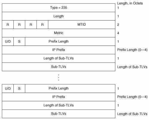
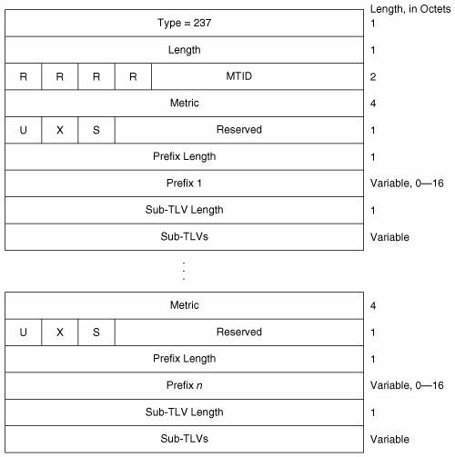
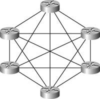
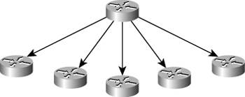
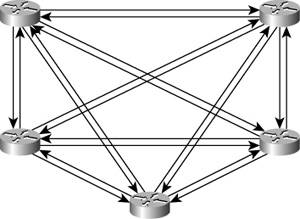
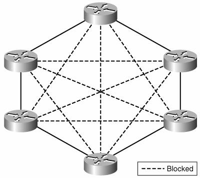
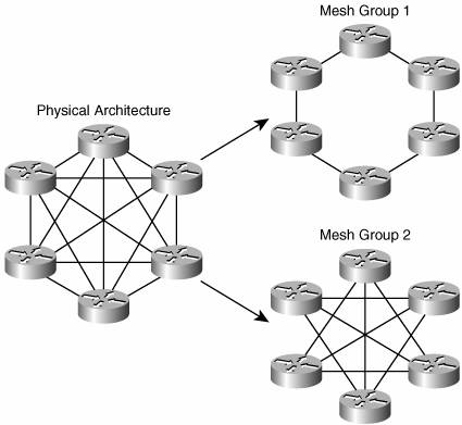
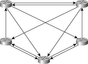
EAN: 2147483647
Pages: 233